
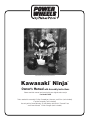
Kawasaki
®
Ninja
®
Owner’s Manual with Assembly Instructions
Please read this manual and save it with your original sales receipt.
For Model 74110
Tools needed for assembly: Phillips Screwdriver, Hammer, and Pliers (not included);
Cap Nut Assembly Tool (included).
Use only with a Power Wheels
®
12 Volt Battery with Built-in Thermal Fuse
and Power Wheels
®
12 Volt Charger (both included).
Product features may vary from the picture above.

2
Table of Contents
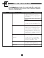
Important Information
A Important Information . . . . . . . . . . . . . . . . . . . . . . . . . . . . . . . . . . . . . . . . . . . . . . . . . . . . . . . . . . . . . . . . . . . . .2
B Warnings and Cautions . . . . . . . . . . . . . . . . . . . . . . . . . . . . . . . . . . . . . . . . . . . . . . . . . . . . . . . . . . . . . . . . . . .3
C Parts . . . . . . . . . . . . . . . . . . . . . . . . . . . . . . . . . . . . . . . . . . . . . . . . . . . . . . . . . . . . . . . . . . . . . . . . . . . . . . . . .4
D Parts Diagram . . . . . . . . . . . . . . . . . . . . . . . . . . . . . . . . . . . . . . . . . . . . . . . . . . . . . . . . . . . . . . . . . . . . . . . . . . .6
E Battery Charging . . . . . . . . . . . . . . . . . . . . . . . . . . . . . . . . . . . . . . . . . . . . . . . . . . . . . . . . . . . . . . . . . . . . . . . . .7
F Assembly . . . . . . . . . . . . . . . . . . . . . . . . . . . . . . . . . . . . . . . . . . . . . . . . . . . . . . . . . . . . . . . . . . . . . . . . . . . . . .9
G Label Decoration . . . . . . . . . . . . . . . . . . . . . . . . . . . . . . . . . . . . . . . . . . . . . . . . . . . . . . . . . . . . . . . . . . . . . . . .15
H Battery Installation . . . . . . . . . . . . . . . . . . . . . . . . . . . . . . . . . . . . . . . . . . . . . . . . . . . . . . . . . . . . . . . . . . . . . .17
I Battery Care and Disposal . . . . . . . . . . . . . . . . . . . . . . . . . . . . . . . . . . . . . . . . . . . . . . . . . . . . . . . . . . . . . . . .18
J Caring For Your Vehicle . . . . . . . . . . . . . . . . . . . . . . . . . . . . . . . . . . . . . . . . . . . . . . . . . . . . . . . . . . . . . . . . . . .18
K Rules For Safe Driving . . . . . . . . . . . . . . . . . . . . . . . . . . . . . . . . . . . . . . . . . . . . . . . . . . . . . . . . . . . . . . . . . . .19
L How to Operate Your Vehicle . . . . . . . . . . . . . . . . . . . . . . . . . . . . . . . . . . . . . . . . . . . . . . . . . . . . . . . . . . . . . . .20
M Statement of Limited Warranty . . . . . . . . . . . . . . . . . . . . . . . . . . . . . . . . . . . . . . . . . . . . . . . . . . . . . . . . . . . . .21
N Problems and Solutions Guide . . . . . . . . . . . . . . . . . . . . . . . . . . . . . . . . . . . . . . . . . . . . . . . . . . . . . . . . . . . . .22
O Authorized Service Centers . . . . . . . . . . . . . . . . . . . . . . . . . . . . . . . . . . . . . . . . . . . . . . . . . . . . . . . . . . . . . . . .25
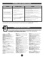
• Your new vehicle requires adult assembly. Please set
aside at least 45 minutes for assembly.
• You must charge your battery for 18 - 30 hours before
you use your vehicle for the first time.We recommend
that you start charging your battery before beginning
assembly. Please see Battery Charging beginning on
page 7 for detailed instructions.
• Read this manual carefully for important safety
information and operating instructions before using
your vehicle.
• This vehicle is designed for use on grass, asphalt and
other hard surfaces, on flat terrain and hills, by children
3 - 7 years of age.
• To prevent damaging the motors and gears, do not tow
anything behind the vehicle or overload it. Do not exceed
the maximum weight capacity of 65 lbs (30 kg).
• For safety reasons, your vehicle has been pre-set so that
it will operate at low speed.Your must disconnect the
high speed lock-out to allow operation of the vehicle at
high speed. Please see page 21 for detailed instructions.
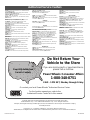
• If you have any questions about your Power Wheels
®
vehicle, please call our toll-free service lines at
1-800-348-0751 from 8 AM to 5 PM (EST) Monday
through Friday. Trained customer service representatives
A
are available to take your call in English or French. Habla
Español? Si usted tiene alguna pregunta ó necesita
asistencia llame gratis 1-800-348-0755 para los Estados
Unidos.Tenemos representantes que hablan español
para atender su llamada.
• For your convenience, Power Wheels
®
maintains an
Authorized Service Center Network with more than
400 authorized service centers nationwide. Our
authorized service centers will repair or replace parts
under warranty at no extra charge, and can perform non-
warranty repairs for a minimal charge. Please see the
Authorized Service Center list beginning on page 25 to
find the authorized service center nearest you, or call
1-800-348-0751.
• Please complete and return the enclosed Registration
Card today, or call 1-800-348-0751 to register your
vehicle by phone.

WARNING
• Children can be harmed by small parts, sharp edges and sharp points in the vehicle’s
unassembled state, or by electrical items. Care should be taken in unpacking and assembly
of the vehicle. Children should not handle parts, including the battery, or help in assembly of
the vehicle.
• Keep small parts and plastic bags out of children’s reach. Dispose of plastic bags properly.
• Adult supervision is required. Children do not have the judgement necessary to avoid many
accidents. Be sure that children operating this vehicle can do so safely and that they are
supervised at all times.
• Never use near steps, driveways, steep inclines, roadways, alleys, swimming pool areas or
other bodies of water.
• Always wear shoes or sneakers when operating this vehicle.
• Never allow more than one rider.
• The rider should sit on the seat when the vehicle is in operation.
• Never alter this vehicle or its electrical system in any way. Alterations could cause a fire
resulting in injury and could also ruin the electrical system.
• Use of the wrong type battery or charger could cause a fire or explosion, resulting in
serious injury.
• Use of Power Wheels
®
components in products other than Power Wheels
®
vehicles could
cause overheating, fire or explosion.
• The battery must be handled by adults only. The battery is heavy and contains sulfuric acid
(electrolyte). Dropping the battery could result in serious injury.
• Read the cautions on the back panel of the battery.
• Never allow children to charge the battery. Battery charging must be done by adults only.
A child could be injured by the electricity involved in charging the battery.
• Examine the battery, charger and their connectors for excessive wear or damage each
time you charge the battery. If damage or excessive wear is detected, do not use the
vehicle until you have replaced the worn or damaged part as it could possibly cause a fire
resulting in injury.
Warnings and Cautions
B
3
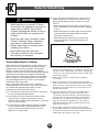
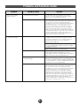
CAUTION
• This product contains small parts. Adult assembly is required.
• Use the charger in dry locations only.

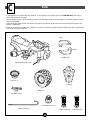
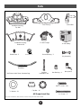
Parts
C
Wheel - 4
• If you experience a problem with this product, or are missing a part, please call us at 1-800-348-0751, rather than
return this product to the store.
• Please identify all parts before assembly and save all packaging material until assembly is complete to ensure that no
parts are discarded.
• Some parts were placed under the seat for shipment. Press the tab under the back of the seat and lift to access the
battery compartment.
• Metal parts have been coated with a lubricant to protect them during shipment.Wipe all metal parts with a paper towel
to remove any excess lubricant.
(Left)
(Right)
Mudflap Set
Rear Wheel Driver - 2
TM
Cowling
Handlebar Neck
Right Hand Grip
Left Hand Grip
Hubcap - 4
Steering Column
Vehicle Body (with Seat)
4

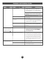
All Shown Actual Size
Not Shown: Label Sheet, Literature Bag
1
1
/
2
" Screw – 2
Cap Nut – 8*
7
/
16
" Washer - 6*
Radio Knob - 2
12 Volt Battery
Hex Bushing - 4
Cap Nut
Installation Tool
Round Bushing - 2
#8 x
3
/
4
" Screw – 19*
Microphone
12-VOLT
CHARGER
12-Volt Charger
Key Assembly
Pb
Lock Nut - 2
*For your convenience, extra washers, screws and cap nuts have been included.
5
Parts
Handlebar Housing -
Top Half
Front Fairing
Handlebar Housing -
Bottom Half
Handlebar
Sound Box

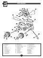
Parts Diagram
D
6
1. Vehicle Body
2. Cowling
3. Seat
4. Wheel - 4
5. Hubcap - 4
6. Cap Nut - 6
7. Steering Column
8. Right Mudflap
9. 12 Volt Battery
10. Key Assembly
11. Microphone
12. Radio Knob - 2
13. Right Hand Grip
14. Handlebar Housing - Top Half
15 Handlebar Housing -
Bottom Half
16. Front Fairing
17. Handlebar
18. Sound Box
19. Handlebar Neck
20. Hex Bushing - 4
21. Round Bushing - 2
22. Lock Nut - 2
23. Rear Wheel Driver - 2
24. #8 x
3
/
4
" Screw - 17
25.
7
/
16
" Washer - 5
26. 1
1
/
2
" Screw - 2
Not Shown
12 Volt Charger
Label Sheet
Left Mudflap
Left Hand Grip
T
M
1
8
3
13
18
17
26
16
15
1
10
12
14
4
23
5
20
6
7
25
21
2
24
24
24
22
19
9
6
25
25

CAUTION
Use the charger in dry locations only.
Battery Charging
E
WARNING
• The battery must be handled by adults
only.The battery is heavy and contains
sulfuric acid (electrolyte). Dropping the
battery could result in serious injury.
• Never allow children to charge the battery.
Battery charging must be done by adults
only. A child could be injured by the
electricity involved in charging the battery.
• Use of the wrong type battery or charger
could cause a fire or explosion, resulting
in serious injury.
• Use of Power Wheels
®
components in
products other than Power Wheels
®
vehicles could cause overheating, fire
or explosion.
• Read the cautions on the back panel of
the battery.
• Examine the battery, charger and their
connectors for excessive wear or damage
each time you charge the battery. If
damage or excessive wear is detected, do
not use the charger or the vehicle
until you have replaced the worn or
damaged part.
• Never alter this vehicle or its electrical
system in any way. Alterations could
cause a fire resulting in injury and could
also ruin the electrical system.
7
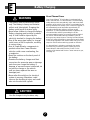
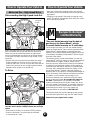
About Thermal Fuses
Your Power Wheels
®
12 volt battery is equipped with a
built-in thermal fuse.The thermal fuse is a self-resetting
safety device which automatically “trips” and shuts down
operation of the vehicle if the vehicle is overloaded or the
driving conditions too severe. Once a fuse has “tripped”, it
will automatically reset itself after approximately 25
seconds and allow the vehicle to resume normal
operations.To avoid repeated automatic shutdowns, do
not overload the vehicle by exceeding the 65 lbs.
maximum weight capacity or by towing anything behind
the vehicle. Avoid severe driving conditions, such as
driving up very steep slopes or running into fixed objects,
which can cause the wheels to stop spinning while power
is still being supplied to the motors. Make sure your child
stops the vehicle before switching speeds or direction.
If a thermal fuse in a battery continually trips under
normal driving conditions, please contact your local
Power Wheels
®
Authorized Service Center. For the
location of the Authorized Service Center nearest to you,
see page 25.

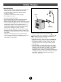
Battery Charging
Pb
• Plug the charger connector into the battery .
• Plug the charger into a standard 120 volt wall outlet .
Note: If power flow to the wall outlet is controlled by a
switch, make sure the switch is “ON”.
• Before first-time use, charge the battery for at least 18
hours. Never charge the battery longer than 30 hours.
• Recharge the battery for at least 14 hours after each
use of your vehicle. Do not charge the battery longer
than 30 hours.
• Once the battery is charged, pull firmly on the charger
connector to disconnect it from the battery. Unplug the
charger from the wall outlet.The battery is now ready to
be installed in your vehicle. Please see the Battery
Installation section on page 17 for detailed instructions on
installing your battery. If your battery is already installed in
your vehicle, simply re-connect the motor harness
connector to the battery.
2
1
Battery
Charger
Connector
8
Important Notes
• Your new battery must be charged for at least 18 hours
before you use it in your vehicle for the first time.
• You do not need to remove the battery from your
vehicle to recharge it.
• The battery must be upright while charging.
• The charger is not a toy.
• Do not short circuit the battery.
• We recommend that you start charging your battery
before beginning assembly of your new vehicle.
• Before charging the battery, examine the battery case for
cracks and other damage which may cause sulfuric acid
(electrolyte) to leak during the charging process. If
damage is detected, do not charge the battery or use it
in your vehicle. Battery acid is very corrosive and can
cause severe damage to surfaces it contacts.
• Do not charge the battery on a surface which could be
damaged by the acid contained inside the battery.Take
precautions to protect the surface on which you charge
your battery.
• Use only a Power Wheels
®
12 volt charger with type
“12V” connector (120 VAC 60 Hz 28W with an output of
12 VDC 1200mA) to charge your Power Wheels
®
rechargeable 12 volt battery.
1
2

Assembly
9
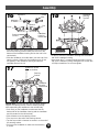
3
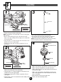
• Position the vehicle body upside down.
Note: The mudflaps are marked “R” and “L” to designate
right and left.
• With the “R” marking facing up, align the two round
holes in the right mudflap with the pegs on the underside
of the right fender.
• Insert two #8 x
3
/4" screws through the round holes in the
mudflap and into the right fender.
• Tighten the screws with a Phillips screwdriver. Do not
over-tighten.
Bottom View
Right
Mudflap
Right Fender
Peg
• Align the two oval holes in the right mudflap with the
pegs on the underside of the right fender.
• Insert two #8 x
3
/4" screws through the oval holes in the
mudflap and into the right fender.
• Tighten the screws with a Phillips screwdriver. Do not
over-tighten.
• Repeat steps 1 and 2 to assemble the left mudflap (“L”)
to the left fender.
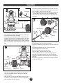
• Fit a cap nut onto one end of the rear axle.
•Tap the other end of the rear axle with a hammer to
secure the cap nut on the end of the rear axle.
Note: You may want to position the cap nut on a scrap
block of wood to protect the assembly surface.
• Slide a hex bushing, ring side first, onto the rear axle.
• Slide a hubcap, ring side first, onto the rear axle.
• Slide a wheel onto the rear axle. Make sure the ribs on
the wheel face up.
• Slide a rear wheel driver, ring side first, onto the rear
axle. Fit the grooves on the rear wheel driver onto the
ribs on the wheel.
•Slide a washer onto the rear wheel axle.
• Set the rear axle assembly aside.
2
1
Bottom View
Right
Mudflap
4
Round Hole
Oval Hole
Rear Axle
Cap Nut
Washer
Wheel
Hex Bushing
Rear Wheel Driver
Hubcap
F

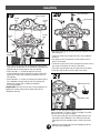
• Slide a washer onto one of the front axles.
• Slide a round bushing, ring side first, onto the same front
axle.
• Slide a wheel (ribbed side first) onto the front axle.
• Slide a hubcap onto the front axle.
•Slide a hex bushing onto the front axle.
• Fit a cap nut on the end of the front axle.
• Fit the cupped end of the cap nut assemby tool over
the cap nut and tap the end of the cap nut assembly
tool with a hammer to secure the cap nut on the end of
the axle.
• Repeat this procedure to assemble the remaining wheel
to the other front axle.
7
Wheel
Round
Bushing
Washer
Hubcap
Hex Bushing
Cap Nut
Assembly
Tool
Cap Nut
10
Assembly
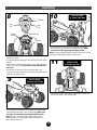
• Position the vehicle body upright.
• Fit and hold a rear wheel driver against the motor pins
on one end of the motor assembly.
• While holding the rear wheel driver in place, slide the
rear axle into the hole in the opposite side of the motor
assembly. Make sure the rear wheel driver on the rear
axle assembly fits onto the pins on the motor assembly.
• Take the rear wheel driver off the open end of the rear
axle.
• Slide a hex bushing, barrel side first, onto the rear axle.
Press all but the ring on the hex bushing into the wheel.
• Fit a cap nut on the end of the rear axle.
• Fit the cupped end of the cap nut assembly tool over the
cap nut and tap the end of the cap nut assembly tool
with a hammer to secure the cap nut on the end of the
rear axle.
5
6
Rear Axle Assembly
Washer
Rear
Wheel Driver
Hex
Bushing
Cap Nut
Cap Nut
Assembly Tool
Hubcap
Rear Axle
Motor Assembly Pins
• Slide a washer onto the rear axle.
• Slide the rear wheel driver onto the rear axle. Make
sure the rear wheel driver fits onto the pins on the
motor assembly.
• Slide a wheel onto the rear axle. Make sure the ribs on
the wheel fit into the grooves on the rear wheel driver.
• Slide a hubcap onto the rear axle.
Rear Wheel Driver

TM
11
Assembly
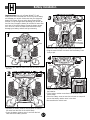
• Press the tab under the back of the seat and lift to
remove the seat.
• Fit the rectangular opening in the cowling over the shifter
handle.
• Align the front, side and rear tabs on the cowling with the
slots in the vehicle body but do not snap the tabs into
the slots.
• Make sure the harness wires are positioned in the
channel to prevent them from being pinched between the
cowling and vehicle body.
T
M
9
Cowling
Shifter
Handle
Side
Tab
Side
Tab
Rear Tab
Channel
PRESS HERE
To Snap Front Tabs
8
• Press firmly on the front of the cowling to snap the four
front tabs into the slots in the vehicle body. Make sure
the side and rear tabs stay aligned with the slots.
Note: Pull up on the front of the vehicle body while
pressing down on the cowling to make sure the front
tabs snap into the slots.
• Press firmly on the back of the cowling to snap the rear
tab into the slots in the vehicle body
T
M
10
11
PRESS HERE
To Snap Side Tabs
PRESS HERE
To Snap Rear Tabs
• Press firmly on each side of the cowling to snap the
four side tabs into the slots in the vehicle body. Make
sure the rear tab stays aligned with the slots.
Note: You may need to flex the shifter to the side to fit the
cowling over the high speed lock-out screw.

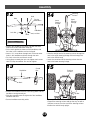
• Lift the front end of the vehicle.
• Slide the straight end of the steering column through the
hole in the upper steering linkage and out through the
hole in the vehicle body.
• Insert the curved end of the steering column into the
hole in the lower steering linkage.
14
15
Steering
Column
Lower
Steering
Linkage
Upper
Steering
Linkage
Hole
Steering
Column
Cap Nut
• Fit a cap nut on the curved end of the steering column.
• Support the steering column and tap the cap nut with a
hammer to secure it on the end of the steering column.
• Position the vehicle body upright.
12
Assembly
Handlebar
Sound
Box
Neck
• Position the handlebar with the neck facing down and the
handlebar curving toward you.
• Slide the soundbox onto the right end of the handlebar,
soundbox side first.
• Set the handlebar assembly aside.
13
• Position the handlebar so that the side with the three
holes and circular indentation faces up.
• Fit the neck against the bottom of the handlebar, with
the holes in the handlebar and neck aligned.
• Insert a 1
1
/2" screw down through each of the two outer
holes in the handlebar and then through the neck.
• Fit a lock nut on the end of each screw.
• Using pliers to steady the lock nuts, tighten each screw
with a Phillips screwdriver. Do not over-tighten.
12
Hole
Hole
Lock Nut
Lock Nut
Handlebar
Circular
Indentation
Neck

13
Assembly
Steering
Column
Handlebar
Neck
Rib
Groove
Sound
Box
Handlebar
Housing -
Bottom Half
• Slide the bottom half of the handlebar housing onto the
end of the steering column. Make sure the rim on the
bottom of the handlebar housing fits into the hole in the
vehicle body.
• Slide the handlebar, neck side down, onto the end of the
steering column. Make sure the handlebar arms fit into
the grooves in the handlebar housing and that the
soundbox fits over the rib.
16
Handlebar
Steering
Column
Handlebar
Housing -
Bottom Half
Cap Nut
Helpful Hint: You may want the help of another adult to
support the steering column near the steering linkage
while assembling the handlebar to the vehicle body.
• Push firmly on the handlebar to make sure that the
bottom half of the handlebar housing and the handlebar
are fully seated on the vehicle body.
• Slide a washer onto the steering column.
• Fit a cap nut on the end of the steering column.
• Tap the cap nut with a hammer to secure it on the end of
the steering column.
• Pull up on the handlebar to make sure the assembly
is secure.
Washer
17
• Fit the top half of the handlebar housing onto the bottom
half of the handlebar housing.
• Insert three #8 x
3
/4" screws through the holes in the top
half of the handlebar housing and tighten the screws with
a Phillips screwdriver. Do not over-tighten.
Handlebar
Housing -
Top Half
18

Assembly
• Fit the front fairing onto the handlebar assembly. Make
sure that the screw tabs on the handlebar assembly are
aligned with the screw pegs on the front fairing.
• Insert four #8 x
3
/4" screws through the top half
of the handlebar housing and into the front fairing and
tighten the screws with a Phillips screwdriver. Do not
over-tighten.
• Insert two #8 x
3
/4" screws up through the bottom half of
the handlebar housing and into the front fairing and
tighten the screws with a Phillips screwdriver.
Do not over-tighten.
Helpful Hint: You may want to use a long screwdriver to
tighten the screws going into the bottom half of the
handlebar housing.
19
Handlebar
Assembly
Screw
Tab
Screw
Peg
Front Fairing
Screw
Tab
Screw
Peg
20
• Bend the plastic tip at the end of the microphone cord so
that it forms a "T".
• Insert the plastic tip through the hole in the handlebar
housing.
• Pull lightly on the microphone cord to make sure it is
secure in the dash.
• Fit the tab on the back of the microphone into the hole in
the center of the dash to hook it to the dash.
• Snap the key assembly into the large hole in the dash.
• Snap the radio knobs into the holes in the dash.
Microphone
Key Assembly
Knobs
Note: The left and right handgrips are not
interchangeable! The hole in the left handgrip is smaller
than the hole in the right handgrip.
• Fit the right hand grip onto the soundbox stem on the
right side of the handlebar. If it is difficult to slide the
hand grip onto the soundbox stem, moisten the hand
grip.
• Repeat this procedure to fit the left handgrip onto the
left side of the handlebar.
Soundbox Stem
Right Hand Grip
21
14

R
15
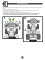
Proper label application will help to keep the labels looking their best! When applying labels, keep the following guidelines
in mind:
• Wash your hands before applying the labels.
• Before applying the labels, wipe the surface of the vehicle with a clean, dry cloth to remove any dust or oils.
• Place the labels exactly as shown in the illustrations.
• For best results, avoid repositioning a label once it has been applied to the vehicle.
• After applying a label, rub the label firmly with a clean, dry cloth to make sure the label is adhered to your
vehicle. Start at the center of a label, and smooth towards the outer edges to remove air bubbles.
Rear View
REMOVE LOCK-OUT
SCREW ON SIDE
OF SHIFTER FOR
HIGH SPEED
OPERATION
7
9276
8
190
170
150
130
110
90
70
50
30
10
10
9
8
7
6
5
4
3
2
1
®
1
2
Label Decoration
G
Dash View
24
16
11
8
9
3
22
23
3

TM
®
®
®
®
VOLT
RECHARGEABLE
BATTERY POWERED
3
T
M
®
®
VOLT
RECHARGEABLE
BATTERY POWERED
4
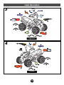
16
Right Side
Left Side
Label Decoration
12
15
18
1
25
26
25
26
13
25
2
4
10
17
20
6
21
26
13
25
26
7
14
10
19
5

17
Important Note: Use only a Power Wheels
®
12 volt
battery with built-in thermal fuse. Use of any other battery
will damage your vehicle. Make sure that you charge the
battery for at least 18 hours using the enclosed Power
Wheels
®
12 volt charger before operating your vehicle for
the first time. Charge the battery for at least 14 hours after
each use of the vehicle. Never charge the battery longer
than 30 hours. Failure to follow these instructions may
damage your battery and will void your warranty.
1
• Press the tab under the back of the seat and lift to remove
the seat.
• Squeeze the battery retainer arms together to release
the arms from the slots in the vehicle body.
• Press the battery retainer arms in and over the lock
tabs and lift the battery retainer.
• Lower the battery retainer over
the batteries.
• Fit the battery retainer arms down into the slots in the
vehicle body.
• Press the battery arms out over the lock tabs to snap and
secure the battery retainer arms in the slots.
• Re-assemble the vehicle seat.
• Place the battery upright in the battery compartment.
• Plug the motor harness connector into the battery. Push
firmly to join.
Vehicle
Body
Seat
Tab
Battery Installation
Battery
Retainer
Arms
Slot
2
Slot
3
Battery
Motor
Harness
Connector
Arm
Arm
Slot
Slot
4
H

If a battery leak develops, avoid contact with the leaking
acid and place the damaged battery in a plastic bag. See
information below for proper disposal.
If acid comes in contact with skin or eyes, flush with
cool water for at least 15 minutes and call a physician.
If acid is internally ingested, give water, milk of
magnesia or egg whites immediately. Never give emetics
or induce vomiting. Call a physician.
• Charge a new battery for at least 18 hours before first
use. Never charge the battery longer than 30 hours.
Overcharging or undercharging the battery may
shorten battery life and decrease vehicle running time.
• After the first charge, recharge the battery for at least
14 hours after each use. Never charge the battery longer
than 30 hours. Charge the battery after each use,
regardless of how long the vehicle was used.
• The battery must be upright while charging.
• Do not allow the battery to run down completely
before charging.
• Charge the battery before storing the vehicle.
• Charge the battery at least once per month, even if
the vehicle has not been used.
• Leaving the battery in a discharged condition will
ruin it.
• Always remove an exhausted battery from the vehicle.
Battery leakage and corrosion can damage the vehicle.
• Do not store the battery on a surface which could be
damaged by the acid contained inside the battery.
Take precautions to protect the surface on which you
store the battery.
• Do not store the battery in temperatures above 75° F or
below -10° F.
• Prevent the battery from moving freely inside the
battery compartment. Always use the battery retainer to
secure the battery in the battery compartment.
• Examine the battery, charger and their connectors for
excessive wear or damage each time you charge the
battery. If damage is detected, do not use the charger
or the battery until you have replaced the worn or
damaged part.
• Your Power Wheels
®
battery is a sealed lead-acid
battery. It must be recycled or disposed of in an
environmentally sound manner.
• Do not dispose of a lead-acid battery in your regular,
household trash.The incineration, landfilling or mixing
of sealed lead-acid batteries with household trash is
prohibited by law in most areas.
• Return the battery to a federal or state approved
lead-acid battery recycler, such as a Power Wheels
®
authorized service center, or a local seller of automotive
batteries. Contact your local waste management
officials for other information regarding the
environmentally sound collection, recycling and disposal
of lead-acid batteries.
18
Care Disposal
Battery Care
and Disposal
I
Battery Care and Disposal
Caring
For Your Vehicle
J
• Check all screws, retainers and their protective coverings
regularly and tighten as required. Check plastic parts on
a regular basis for cracks or broken pieces.
• During snowy or rainy weather, the vehicle should be
stored inside or under a protective cover. Remember to
charge the battery at least once per month while your
vehicle is not in regular use.
• Avoid operating the vehicle in wet or snowy conditions,
and do not spray the vehicle with a hose. Do not wash
the vehicle with soap and water. Water or moisture in the
motors or electrical switches can cause them to corrode,
and could cause switch or motor failure.
• Avoid operating the vehicle on sand, loose dirt or gravel.
Sand, loose dirt or gravel in the motors or electrical
switches can cause them to jam, and could cause switch
or motor failure.
• The vehicle can be wiped down with a soft, dry cloth. For
a shiny finish, you can wipe plastic parts with a non-wax
furniture polish applied to a soft-cloth. Do not use
automotive wax. Do not use soap and water or spray the
vehicle with a hose.
• To ensure that your vehicle stays in good operating order,
we recommend that you periodically have your vehicle
checked by a Power Wheels
®
authorized service center.
See page 25 for the list of authorized service centers or
call 1-800-348-0751 for the location of the authorized
service center nearest you.

10°
Incline should never be
more than 10°
5. Do not operate this vehicle with more than one rider,
seated on the seating area. A child who is not sitting on
the seat or who is standing on the vehicle could fall off,
cause a tip-over or block the driver’s view. A child could
be seriously injured.
6. Always wear shoes or sneakers when operating
this vehicle.
7. Never put anything near any moving parts. Rotating
parts such as motors, gear boxes and wheels can snag
fingers, hair, etc., causing serious injury. Do not allow
operation of the vehicle when it is on its side or in an
upside-down position.
8. Do not operate the vehicle near flammable vapors
(gasoline, paint thinner, acetone, liquid wax, etc.).
The vehicle’s electrical switches, like most electrical
switches, emit an internal spark when first turned on
or turned off.The presence of flammable liquids or
vapors could cause an explosion or a fire. Keep all
flammable products in tightly sealed containers and
away from the vehicle.
9. Do not allow a child to operate the vehicle without
proper adult supervision.To prevent unsupervised use
of the vehicle, disconnect the motor harness from the
battery when the vehicle is not in use.
19
Teach Safety Rules to Children
While children can quickly develop the skill necessary to
drive this vehicle, it is important to remember that their
judgment skills are still very immature. Unsupervised
driving by children can lead to serious injury. Before
children use this vehicle, an adult should carefully evaluate
the driving area as well as the children’s skill level and
ability to drive this vehicle safely. Children are not always
able to recognize or anticipate hazards, even when they
have been taught about them.There is no acceptable
substitute for adult supervision.
Teach appropriate safety rules to your child before
allowing operation of this vehicle.These rules should also
be reviewed with neighborhood children or other
playmates who want to drive this vehicle.
1. Do not allow any child to drive the vehicle in the street
or near moving (motorized) vehicles.
2. Do not allow any child to drive near bodies of water
(such as pools or creeks), obstructions (such as
furniture, low tree limbs or play equipment), or drop-offs
(such as stairs or decks).
3. Do not allow any child to drive the vehicle in the dark.
A child could encounter unexpected obstacles and
have an accident. Operate the vehicle only in the
daytime or in a well-lit area.
4. Teach your child to avoid driving on steep inclines or
slopes. Restrict your child’s driving to areas that are
fairly level with gentle inclines or slopes of no more
than 10°.
• While driving down a steep slope, the vehicle may
gain unsafe speed, even if the foot pedal is released
to stop.
• While driving across a steep slope, the vehicle may
tilt and tip over. The wheels could lose traction,
causing the vehicle to slip.
• While driving up a steep incline, the motor may
stop and the vehicle could roll backwards at an
unsafe speed.
WARNING
• Adult supervision is required. Children
do not have the judgement necessary to
avoid many accidents. Be sure that
children operating this vehicle can do so
safely and that they are supervised at
all times.
• Never use near steps, driveways, steep
inclines, roadways, alleys, swimming
pool areas or other bodies of water.
• Always wear shoes or sneakers when
operating this vehicle.
• Never allow more than one rider.
• The rider should sit on the seat when
the vehicle is in operation.
Rules for Safe Driving
K

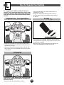
• Make sure the shifter is in the LOW SPEED position.
• Press the foot pedal.The vehicle will drive forward at a
maximum of 2
1
/2 mph.
• Help your child practice steering to learn how far and
how quickly to turn the handlebar when driving forward
in low speed.
• Your vehicle has a patented, electronic braking system
that automatically stops the vehicle when your child’s foot
is lifted from the pedal.
• Make sure your child is comfortable with steering the
vehicle and automatically knows how to stop.
20
Beginner Use - Low Speed Drive
To Stop
Please Note:To avoid damaging the motors and gears,
make sure to stop the vehicle before switching from
forward to reverse.
• Move the shifter to the REVERSE position.
REMOVE LOCK-OUT
SCREW ON SIDE
OF SHIFTER FOR
HIGH SPEED
OPERATION
REMOVE LOCK-OUT
SCREW ON SIDE
OF SHIFTER FOR
HIGH SPEED
OPERATION
Shifter
Shifter
How to Operate Your Vehicle
L
As assembled, your vehicle is ready to roll in low
speed (2
1
/2 mph, maximum).When your child is ready
to drive the vehicle in high speed (5 mph, maximum),
follow the instructions to disconnect the high speed
lock-out.
To Back Up
• Press the foot pedal.The vehicle will back-up at a
maximum of 2
1
/2 mph.
• Help your child practice steering to learn how far
and how quickly to turn the handlebar when driving
in reverse.
Page is loading ...
Page is loading ...
Page is loading ...
Page is loading ...
Page is loading ...
Page is loading ...
Page is loading ...
Page is loading ...
-
 1
1
-
 2
2
-
 3
3
-
 4
4
-
 5
5
-
 6
6
-
 7
7
-
 8
8
-
 9
9
-
 10
10
-
 11
11
-
 12
12
-
 13
13
-
 14
14
-
 15
15
-
 16
16
-
 17
17
-
 18
18
-
 19
19
-
 20
20
-
 21
21
-
 22
22
-
 23
23
-
 24
24
-
 25
25
-
 26
26
-
 27
27
-
 28
28


Ask a question and I''ll find the answer in the document
Finding information in a document is now easier with AI
Related papers
-
Power Wheels 73690 User manual
-
Kawasaki 73690 User manual
-
-
Hot Wheels CATERPILLAR 73260 User manual
-
-
-
Power Wheels PW TRU Harley Owner's manual
-
Hot Wheels B9272 User manual
-
-
Other documents
-
-
 Lil Rider W41-0068 Operating instructions
-
 Lil Rider W410064 Operating instructions
-
VESPA PX 150 Euro 3 Workshop Manual
-
-
-
Difrnce MP1871 BLUE Datasheet
-
Amplicomms TV SoundBox Operating instructions
-
DAVIS 253 Owner's manual
-
Drive Medical Exercise Peddler Owner's manual

