Page is loading ...

by
Digital Inverter 200 W,
400 W, 800 W
Owner’s Guide
XP_Digital_200-400-800.book Page i Wednesday, October 26, 2005 2:51 PM

About Xantrex
Xantrex Technology Inc. is a world-leading supplier of advanced power electronics and
controls with products from 50 watt mobile units to one MW utility-scale systems for
wind, solar, batteries, fuel cells, microturbines, and backup power applications in both
grid-connected and stand-alone systems. Xantrex products include inverters, battery
chargers, programmable power supplies, and variable speed drives that convert, supply,
control, clean, and distribute electrical power.
Trademarks
Digital Inverter 200 W, 400 W, 800 W is a trademark of Xantrex International. Xantrex is
a registered trademark of Xantrex International.
Other trademarks, registered trademarks, and product names are the property of their
respective owners and are used herein for identification purposes only.
Notice of Copyright
Digital Inverter 200 W, 400 W, 800 W Owner’s Guide © October 2005 Xantrex
International. All rights reserved.
Disclaimer
UNLESS SPECIFICALLY AGREED TO IN WRITING, XANTREX TECHNOLOGY INC. (“XANTREX”)
(a) MAKES NO WARRANTY AS TO THE ACCURACY, SUFFICIENCY OR SUITABILITY OF ANY
TECHNICAL OR OTHER INFORMATION PROVIDED IN ITS MANUALS OR OTHER DOCUMENTATION.
(b) ASSUMES NO RESPONSIBILITY OR LIABILITY FOR LOSS OR DAMAGE, WHETHER DIRECT,
INDIRECT, CONSEQUENTIAL OR INCIDENTAL, WHICH MIGHT ARISE OUT OF THE USE OF SUCH
INFORMATION. THE USE OF ANY SUCH INFORMATION WILL BE ENTIRELY AT THE USER’S RISK.
Date and Revision
October 2005 Revision B
Part Number
975-0176-01-01
Contact Information
Telephone: 1 360-925-5097
Fax: 1 360-925-5143
Web: www.xantrex.com/support
XP_Digital_200-400-800.book Page ii Wednesday, October 26, 2005 2:51 PM

1. Introduction . . . . . . . . . . . . . . . . . . . . . . . . . . . . . . . . . . . . . . . . . . 1
About This Guide . . . . . . . . . . . . . . . . . . . . . . . . . . . . . . . . . . . . . 2
2. Important Safety Information. . . . . . . . . . . . . . . . . . . . . . . . . . . . 3
Warnings and Cautions . . . . . . . . . . . . . . . . . . . . . . . . . . . . . . . . . 3
Additional Safety Guidelines . . . . . . . . . . . . . . . . . . . . . . . . . . . . 5
3. Digital Inverter Features . . . . . . . . . . . . . . . . . . . . . . . . . . . . . . . . 6
AC (Front) Panel . . . . . . . . . . . . . . . . . . . . . . . . . . . . . . . . . . . . . . 6
DC (Back) Panel . . . . . . . . . . . . . . . . . . . . . . . . . . . . . . . . . . . . . . 8
Digital Display (Top) Panel . . . . . . . . . . . . . . . . . . . . . . . . . . . . . 10
Types of Connections . . . . . . . . . . . . . . . . . . . . . . . . . . . . . . . . . 12
Accessories . . . . . . . . . . . . . . . . . . . . . . . . . . . . . . . . . . . . . . . . . 13
4. Connecting the Digital Inverter . . . . . . . . . . . . . . . . . . . . . . . . . 14
Choosing a Location . . . . . . . . . . . . . . . . . . . . . . . . . . . . . . . . . . 14
Connecting for Loads Under 150 W . . . . . . . . . . . . . . . . . . . . . . 15
Connecting for Loads Over 150 W . . . . . . . . . . . . . . . . . . . . . . . 16
5. Operating the Digital Inverter . . . . . . . . . . . . . . . . . . . . . . . . . . 19
Operating Conditions and Guidelines . . . . . . . . . . . . . . . . . . . . . 19
Shutting the inverter off . . . . . . . . . . . . . . . . . . . . . . . . . . . . . . 20
Operating normal loads . . . . . . . . . . . . . . . . . . . . . . . . . . . . . . 21
Operating loads with high surge requirements. . . . . . . . . . . . . 22
Contents
XP_Digital_200-400-800.book Page iii Wednesday, October 26, 2005 2:51 PM

iv
6. Maintaining Battery Condition . . . . . . . . . . . . . . . . . . . . . . . . . .24
7. Troubleshooting. . . . . . . . . . . . . . . . . . . . . . . . . . . . . . . . . . . . . . .26
Common Problems . . . . . . . . . . . . . . . . . . . . . . . . . . . . . . . . . . . 27
Buzz in audio systems. . . . . . . . . . . . . . . . . . . . . . . . . . . . . . . . 27
Television interference . . . . . . . . . . . . . . . . . . . . . . . . . . . . . . . 27
Troubleshooting Reference . . . . . . . . . . . . . . . . . . . . . . . . . . . . 28
8. Specifications . . . . . . . . . . . . . . . . . . . . . . . . . . . . . . . . . . . . . . . . .31
9. Warranty and Return. . . . . . . . . . . . . . . . . . . . . . . . . . . . . . . . . .33
10. Other Xantrex Products . . . . . . . . . . . . . . . . . . . . . . . . . . . . . . .39
XP_Digital_200-400-800.book Page iv Wednesday, October 26, 2005 2:51 PM

1
1 Introduction
Thank you for purchasing the XPower Digital Inverter 200 W, 400 W,
800 W. These Digital Inverters are part of a family of advanced high-
performance power inverters from Xantrex, the leader in high frequency
inverter design.
Connected to the 12 volt outlet in your car, truck, boat, RV, or directly
from a dedicated 12 V battery (400 and 800 W only), the Digital
Inverter efficiently and reliably powers a wide variety of household AC
products, such as portable stereos, laptop computers, TVs, VCRs, and
other similar products.
The Digital Inverter uses reliable solid state power electronics for years
of safe, trouble-free operation and includes the following automatic
features to ensure safe and trouble-free operation:
• Low battery alarm
• Low voltage shutdown
• High voltage shutdown
• Overload shutdown
• Overheating shutdown
• Short-circuit protection
XP_Digital_200-400-800.book Page 1 Wednesday, October 26, 2005 2:51 PM

2
About This Guide
To get the best performance from your Digital Inverter, we recommend
that you read this guide before connecting and using the Digital
Inverter. Save this guide for future reference.
This guide contains:
• Important safety information (page 3)
• Digital Inverter features (page 6)
• Instructions for connecting the inverter (page 14)
• Operating guidelines (page 19)
• Troubleshooting information (page 26)
• Specifications (page 31)
• Warranty and service information (page 33)
XP_Digital_200-400-800.book Page 2 Wednesday, October 26, 2005 2:51 PM

3
2 Important Safety Information
Misusing or incorrectly connecting the Digital Inverter 200 W, 400 W,
800 W may damage the equipment or create hazardous conditions for
users. Read the following safety instructions and pay special attention to
all Caution and Warning statements in the guide.
Warnings identify
conditions that may result in personal injury or loss
of life.
Cautions identify conditions or practices that may damage the unit or
other equipment.
Warnings and Cautions
WARNING: Shock hazard
Keep children away from the Digital Inverter inverter. The inverter
generates the same potentially lethal AC power as a normal household
wall outlet. Treat the outlet with respect!
WARNING: Heated surface
The Digital Inverter housing may become uncomfortably warm,
reaching 140° F (60° C) under extended high power operation. Ensure
that at least 2 inches (5 cm) of air surround the inverter. During
operation, keep it away from materials that may be affected by high
temperatures.
XP_Digital_200-400-800.book Page 3 Wednesday, October 26, 2005 2:51 PM

4
WARNING: Explosion hazard
Do not use the Digital Inverter in the presence of flammable fumes or
gases, such as in the bilge of a gasoline powered boat, or near propane
tanks. Do not use the Digital Inverter in an enclosure containing
automotive-type, lead-acid batteries. These batteries, unlike sealed
batteries, vent explosive hydrogen gas, which can be ignited by sparks
from electrical connections.
WARNING: Crash hazard
Vehicle drivers should not configure or troubleshoot the Digital Inverter
while they are driving the vehicle.
CAUTION: Output non-sinusoidal
Some chargers for small nickel-cadmium batteries can be damaged if
connected to the Digital Inverter. Do not use the inverter with the
following appliances:
• Small battery-operated appliances like rechargeable flashlights,
some rechargeable shavers, and night lights that are plugged directly
into an AC receptacle to recharge.
• Battery chargers used in hand power tools. These chargers display a
warning label stating that dangerous voltages are present at the
charger battery terminals.
XP_Digital_200-400-800.book Page 4 Wednesday, October 26, 2005 2:51 PM

5
Additional Safety Guidelines
• Do not insert foreign objects in the Digital Inverter outlets or
ventilation openings.
• Never connect the inverter to power utility AC distribution wiring.
• Do not use the Digital Inverter in temperatures over 100° F (40° C).
• Do not expose the Digital Inverter to water, rain, snow, or spray.
Failure to follow these safety guidelines may cause personal injury and/
or damage to the Digital Inverter. It may also void your product
warranty.
CAUTION
Do not connect live AC power to the Digital Inverter’s AC outlets. The
inverter will be damaged even if it is turned off.
Do not connect any AC load that has its neutral conductor connected to
ground to the Digital Inverter.
XP_Digital_200-400-800.book Page 5 Wednesday, October 26, 2005 2:51 PM

6
3 Digital Inverter Features
This section describes the main features of the Digital Inverter.
AC (Front) Panel
Figure 1 shows the AC panel of the 200 W unit.
Figure 1
AC Panel of 200 W unit
An AC receptacle is located on one end of the 200 W unit. You can plug
in 120 V appliances with a combined total continuous power
consumption of 160 W or less when the inverter is turned on.
CAUTION
To prevent overheating, ensure that all the ventilation openings on the
unit are kept clear.
OUTPUT: 115 VAC 60 HZ
160 W/1.4A Continuous
XP_Digital_200-400-800.book Page 6 Wednesday, October 26, 2005 2:51 PM

7
Figure 2 shows the AC panel of the 400 W unit, which is very similar to
the 800 W unit.
Two AC receptacles are located on one end of the 400 W unit and the
800 W unit. You can plug in 120 V appliances with a combined total
continuous power consumption of 320 W (400 W unit) or 640 W
(800 W unit) or less when the inverter is turned on.
Figure 2
AC Panel of 400 W unit
XP_Digital_200-400-800.book Page 7 Wednesday, October 26, 2005 2:51 PM

8
DC (Back) Panel
Figure 3 shows the DC panel of the 200 W unit. Use Table 1 to identify
the function of items.
Figure 4 shows the DC panel of the 800 W unit, which is very similar to
the 400 W unit. Use Table 1 to identify the function of items.
Figure 3
DC Panel of 200 W unit
Figure 4
DC Panel of 800 W unit
2A
1
2B
2A
1
2B
XP_Digital_200-400-800.book Page 8 Wednesday, October 26, 2005 2:51 PM

9
Table 1
DC Panel Functions
Item Function
1
Fan and Ventilation Openings
The cooling fan on the units are designed to operate only when
output power is greater than approximately 80 W. When the inverter
is turned on, the fan may operate momentarily. The ventilation
openings should not be covered at any time while the inverter is
operating.
2
A) Positive and B) Negative Cabling Terminals
Connect the ring terminals on the power cables to these terminals. To
ensure correct polarity, red must be connected to red and black must
be connected to black.
XP_Digital_200-400-800.book Page 9 Wednesday, October 26, 2005 2:51 PM

10
Digital Display (Top) Panel
Figure 5 shows the Digital Display panel. Use Table 2 to identify the
function of items.
Figure 5
Digital Display Panel
2
1
3
XP_Digital_200-400-800.book Page 10 Wednesday, October 26, 2005 2:51 PM

11
Table 2
Digital Display Panel Functions
Item Function
1 Switch to turn the unit on and off.
Press to toggle the display function to show input voltage, output
power and output voltage.
2 Normal Operation
Digital display shows input voltage, output power and output
voltage.
Error Mode
Digital display shows error codes and alarm sounds when unit has
shut down due to under-voltage, over-voltage, over-load, overheating
or high-surge.
3 LEDs indicate the status of the digital display.
Audible Alarm
An audible alarm warns you if an under-voltage shutdown is about to
occur.
XP_Digital_200-400-800.book Page 11 Wednesday, October 26, 2005 2:51 PM

12
Types of Connections
Product Lighter Plug Connection
Cable Clamps/Battery
Connections
200 W unit Available – You must connect
a separate lighter plug cable
(included).
Not Available
400 W unit Available – You must connect
a separate lighter plug cable
(included).
Available – You must connect
a separate battery clamp cable
(included).
800 W unit Not Available Available – You must connect
a separate battery clamp cable
(included).
XP_Digital_200-400-800.book Page 12 Wednesday, October 26, 2005 2:51 PM

13
Accessories
Figure 6 shows the lighter plug cable that is included with the 200 W
unit and 400 W unit.
Figure 7 shows the cable supplied with the 400 W unit and 800 W unit
for direct connection to a 12 V battery.
Figure 6
Lighter Plug Cable
Figure 7
Cable for Direct Connection to a 12 V Battery
XP_Digital_200-400-800.book Page 13 Wednesday, October 26, 2005 2:51 PM

14
4 Connecting the Digital Inverter
It is recommended that you hard wire the 800 W unit directly to the
12 V battery.
Choosing a Location
For best performance, place the inverter on a flat surface in a location
that is:
CAUTION
The Digital Inverter must only be connected to a battery that has a
nominal output of 12 V. It will not operate if connected to a 6 V battery
and may be damaged if connected to a battery with 16 V or more.
Dry Do not expose the inverter to water, rain, snow or spray.
Cool Operate the inverter in ambient temperatures between 0°C
and 40 °C (32 °F and 100 °F). Keep it away from heating
vents and direct sunlight.
Well-ventilated For proper cooling, allow at least 2 inches (5 cm) of
clearance around the inverter.
Clean and free of
dust and dirt
Choose a location that is free of any debris that could get
into the inverter.
Safe Do not install the inverter in a compartment with batteries
or flammable liquids, such as gasoline, or explosive vapors.
XP_Digital_200-400-800.book Page 14 Wednesday, October 26, 2005 2:51 PM

15
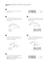
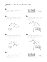
Connecting for Loads Under 150 W
Follow these steps to connect the 200 W unit or 400 W unit:
1. Place the inverter on a flat surface such as the floor of your vehicle.
2. Make sure that the unit is off by verifying the digital display is off.
3. Take the power cord equipped with the lighter plug (Figure 6) and
place the ring terminals over the two cabling terminals on the back
of the inverter. (The cabling terminals are shown in Figure 3 and
Figure 4.)
4. Fasten the positive (red) clamp to the positive battery post, and then
fasten the negative (black) clamp to the negative battery post.
CAUTION: Reverse polarity
Power connections of the 12 V DC battery to the Digital Inverter must
be positive to positive and negative to negative.
A reverse polarity connection (positive to negative) will blow a fuse in
the inverter and may permanently damage the unit. Damage caused by a
reverse polarity connection is not covered by your warranty.
CAUTION
Make sure you connect red to red and black to black, and make sure you
screw the nuts on tightly.
XP_Digital_200-400-800.book Page 15 Wednesday, October 26, 2005 2:51 PM

16
5. Tighten the nut on each DC terminal until it is snug. Do not
over-tighten.
6. Place the inverter’s lighter plug in the vehicle’s lighter socket or a
12 V outlet.
7. Turn on the unit by holding the switch located on top of the unit
until 888 is shown on the display.
The digital display will show the battery voltage, indicating that the
Digital Inverter is operating normally and AC power is available at
the outlet.
8. Plug in the AC product you want to operate.
When not in use always turn the inverter off by holding the switch until
the digital display turns off.
Connecting for Loads Over 150 W
You must connect the 400 W unit or 800 W unit directly to a 12 V
battery if you are going to operate loads greater than 150 W
continuously. When the inverter is connected this way, you can operate
loads of any size up to 320 W continuously with a 400 W unit and
640 W continuously with a 800 W unit.
XP_Digital_200-400-800.book Page 16 Wednesday, October 26, 2005 2:51 PM
/