
Frymaster, a member of the Commercial Food Equipment Service Association, recommends
using CFESA Certified Technicians.
24-Hour Service Hotline 1-800-551-8633 FEB 11
*8195246*
Electric Cooker Models
8SMS, 8BC and 8C
Installation, Operation, Service, and Parts Manual

www.frymaster.com Frymaster Domestic
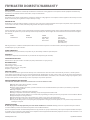
FRYMASTER DOMESTIC WARRANTY
WHAT IS COVERED
This warranty covers all defects in workmanship and material in all commercial cooking appliances and computer/controller equipment manufactured by
Frymaster and sold within the domestic United States, except as excluded below.
WHO IS COVERED
This warranty covers only the original purchaser of Frymaster commercial cooking appliances and computer/controller equipment. This warranty is not trans-
ferable. You must have your original sales receipt for warranty coverage.
WHAT WE WILL DO
We will repair or replace the defective appliance, component, or part. Such repair or replacement will be at the expense of Frymaster, LLC; except that travel
over 100 miles or two hours, overtime, and holiday charges will be at the expense of the purchaser.
FRYPOT WARRANTY
Stainless steel frypots on all fryers, except as noted below, are warranted against manufacturing defects and/or weld seam failure for the lifetime of the fryer;
parts and labor, except after one year, the warranty is limited to replacement parts. Stainless frypots for models listed below are warranted for the length of
time indicated.
1 Year 5 Years 7 Years 10 Years
All Cold Rolled GF14, GF40 H55 (Effective Pasta Systems
May 1, 1998) (Gas and Electric)
Gas Protector Rethermalizer
Water Bath Station
(Gas and Electric)
H55 and gas Protector® combustion chamber (infrared burners and structural components to mount the burners) warranted against defective material or
workmanship for 7 years, parts and labor.
FENWAL THERMOSTATS
Warranted for two years, parts and labor, except after one year, the warranty is limited to replacement parts.
OTHER PARTS
All other parts components are warranted for one year from the date of purchase (parts and labor).
SHORTENING DISPOSAL UNIT
Warranted for 90 days parts and labor. In addition, the pump is warranted for one year, parts only.
REPLACEMENT PARTS
Parts, 90 days, no labor
Mild steel frypot, 90 days, no labor
Stainless Steel frypots, 1 year, 90 days labor
Computers, 1 year, no labor
HOW TO GET SERVICE
Contact our Authorized Service Agent to obtain warranty service. To find the name and location of the nearest ASA call your dealer, or call the Frymaster
Service Hotline, 800-551-8633. You can also go to the Frymaster website, www.frymaster.com, click on Service, click on Locator, key in zip code and it will give
you the ASA for that zip code. When calling for service, please furnish the model number, serial number, series code number, voltage of your appliance, and a
description of the problem. You must keep your sales receipt for proof of your date of purchase.
WHAT THIS WARRANTY DOES NOT COVER
THE WARRANTIES PROVIDED BY FRYMASTER, LLC DO NOT APPLY IN THE FOLLOWING INSTANCES:
+ Damage due to misuse, abuse, alteration, or accident.
+ Improper or unauthorized repair.
+ Failure to follow installation procedures, operation instructions and/or scheduled maintenance procedures as prescribed in your Frymaster
Service and Owner’s Manual.
+ Damage in shipment.
+ Removal, alteration, or obliteration of the rating plate.
+ Changes in adjustment and calibrations after thirty (30) days from equipment installation date.
+ Failure to program computer appliances in accordance with programming procedures prescribed in your Frymaster Service and Owner’s Manual.
+ Equipment exported to foreign countries.
+ Normal maintenance items such as electric bulbs, fuses, gaskets, o-rings, interior and exterior finishes.
+ Travel over 100 miles or two hours, overtime or holiday charges; all of which must be paid for by the purchaser.
+ Consequential damages (the cost of repairing other property which is damaged), loss of time, profits, use or any other non-fryer related inciden-
tal damages of any kind.
GENERAL EXCLUSIONS
No warranty is provided for any Frymaster fryer used in a mobile installation or concession. Warranty protection is only offered for fryers installed in
accordance with the procedures described in the Frymaster Service and Owner’s Manual.
There are no implied warranties of merchantability of fitness for any particular use or purpose. This warranty is the only and complete statement with respect
to warranties of your commercial cooking appliances and computer/controller equipment manufactured by Frymaster. There are no other documents or oral
statements for which Frymaster will be responsible.

THIS EQUIPMENT IS INTENDED FOR INDOOR USE ONLY.
DO NOT INSTALL OR OPERATE THIS EQUIPMENT IN OUTDOOR AREAS.
DO NOT OPERATE THIS EQUIPMENT WITHOUT FIRST READING THIS MANUAL.
DO NOT OPERATE THIS EQUIPMENT UNLESS ALL COVERS AND ACCESS PANELS ARE IN PLACE AND
PROPERLY SECURED.
DO NOT ATTEMPT TO REPAIR OR REPLACE ANY COMPONENT OF THIS EQUIPMENT UNLESS ALL
POWER TO THE UNIT HAS BEEN DISCONNECTED.
IF THE POWER SUPPLY CORD IS DAMAGED, IT MUST BE REPLACED BY THE MANUFACTURER OR ITS
SERVICE AGENT OR SIMILARLY QUALIFIED PERSONS IN ORDER TO AVOID A HAZARD.
USE CAUTION WHEN SETTING UP, OPERATING, OR CLEANING THIS EQUIPMENT TO AVOID CONTACT
WITH HEATED SURFACES.
DO NOT USE WATER JETS TO CLEAN THIS EQUIPMENT.
THIS EQUIPMENT IS TO BE INSTALLED IN COMPLIANCE WITH THE BASIC PLUMBING CODE OF THE
BUILDING OFFICIALS AND CODE ADMINISTRATORS INTERNATIONAL, INC. (BOCA) AND THE FOOD
SERVICE SANITATION MANUAL OF THE FOOD AND DRUG ADMINISTRATION.
DANGER
IMPROPER INSTALLATION, ADJUSTMENT, ALTERATION, SERVICE, OR MAINTENANCE CAN CAUSE
PROPERTY DAMAGE, INJURY, OR DEATH. READ THE INSTALLATION, OPERATING, AND SERVICE
INSTRUCTIONS THOROUGHLY BEFORE INSTALLING OR SERVICING THIS EQUIPMENT.
DANGER
FOR YOUR SAFETY, DO NOT STORE OR USE GASOLINE OR OTHER FLAMMABLE LIQUIDS OR VAPORS
IN THE VICINITY OF THIS OR ANY OTHER APPLIANCE.
COMPUTERS
FCC
This device complies with Part 15 of the FCC rules. Operation is subject to the following two conditions:
1) This device may not cause harmful interference, and 2) This device must accept any interference
received, including interference that may cause undesired operation. While this device is a verified Class
A device, it has been shown to meet the Class B limits.
CANADA
This digital apparatus does not exceed the Class A or B limits for radio noise emissions as set out by the
ICES-003 standard of the Canadian Department of Communications.
Cet appareil numerique n’emet pas de bruits radioelectriques depassany les limites de classe A et B
prescrites dans la norme NMB-003 edictee par le Ministre des Communcations du Canada.
DANGER
THIS PRODUCT CONTAINS CHEMICALS KNOWN TO THE STATE OF CALIFORNIA TO CAUSE CANCER
AND/OR BIRTH DEFECTS OR OTHER REPRODUCTIVE HARM.
Operation, installation, and servicing of this product could expose you to airborne particles of glasswool
or ceramic fibers, and/or crystalline silica. Inhalation of airborne particles of glasswool or ceramic fibers
is known to the State of California to cause cancer.
FRYMASTER FRYERS EQUIPPED WITH LEGS ARE FOR PERMANENT INSTALLATION. FOR MOVEABLE
OR PORTABLE INSTALLATION, FRYMASTER OPTIONAL EQUIPMENT CASTERS MUST BE USED.
QUESTIONS??? CALL 1-800-551-8633.
Do not use deliming solution to clean water bath units. Use of deliming solution will damage all stainless
steel parts.

i
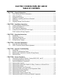
ELECTRIC COOKERS 8SMS, 8BC AND 8C
TABLE OF CONTENTS
CHAPTER 1: General Information
1.1 Parts Ordering and Service Information..........................................................................1-1
1.2 Safety Information...........................................................................................................1-1
1.3 Equipment Description ....................................................................................................1-2
1.4 Installation, Operating, and Service Personnel................................................................1-2
1.5 Definitions........................................................................................................................1-3
1.6 Shipping Damage Claim Procedure.................................................................................1-3
CHAPTER 2: Installation Instructions
2.1 General Installation Requirements................................................................................... 2-1
2.2 Caster/Leg Installation.....................................................................................................2-2
2.3 Pre-Connection Preparations ...........................................................................................2-2
2.4 Connecting to the Electrical Power Supply.....................................................................2-3
Field Connection Wiring Diagrams.................................................................................2-4
CHAPTER 3: Operating Instructions
3.1 Introduction......................................................................................................................3-1
3.2 Operating Instructions......................................................................................................3-2
3.3 Shutting the Cooker Down...............................................................................................3-2
3.4 Boiling Out the Cookpot.................................................................................................. 3-3
CHAPTER 4: Preventive Maintenance
4.1 Daily Preventive Maintenance......................................................................................... 4-1
4.2 SMS II Controller Simmer Mode Adjustment................................................................. 4-2
CHAPTER 5: Operator Troubleshooting
5.1 Introduction......................................................................................................................5-1
5.2 Operator Troubleshooting Guides....................................................................................5-2
5.3 Replacing the Controller or Controller Wiring Harness..................................................5-3
5.4 Replacing Fuses...............................................................................................................5-4
CHAPTER 6: Service Procedures
6.1 Functional Description of Electric Cookers 8SMS, 8BC, and 8C................................... 6-1
6.2 Accessing Equipment for Servicing.................................................................................6-2
6.3 Replacing Equipment Components..................................................................................6-2
6.3.1 Replacing the Controller..................................................................................................6-2
6.3.2 Replacing the Transformer, Basket Lift Relay, Contactor, or Solenoid Valve ...............6-2
6.3.3 Replacing the Element.....................................................................................................6-3
6.3.4 Replacing the High-Limit Thermostat.............................................................................6-4
6.3.5 Replacing a Water Level Sensor or the Temperature Probe............................................6-5
6.3.6 Replacing the Pressure Regulator....................................................................................6-6
6.3.7 Replacing the Water Faucet.............................................................................................6-7
6.3.8 Replacing the Cookpot or Rinse Tank.............................................................................6-8
6.3.9 Replacing the Basket Lift Motor and Related Components ..........................................6-10

ii
6.4 Troubleshooting.............................................................................................................6-11
6.4.1 How the Autofill System Works....................................................................................6-11
6.4.2 How the Water Heating System Works.........................................................................6-11
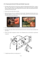
6.4.3 Technician Troubleshooting Guides..............................................................................6-12
Troubleshooting the Autofill System.............................................................................6-12
Troubleshooting the Basket Lift ....................................................................................6-13
Troubleshooting the Controller......................................................................................6-14
Troubleshooting the Contactor Coil...............................................................................6-15
Troubleshooting the High-Limit Thermostat.................................................................6-15
Troubleshooting the Temperature Probe .......................................................................6-15
6.5 Wiring Diagrams............................................................................................................6-16
CHAPTER 7: Parts List
7.1 Accessories ......................................................................................................................7-1
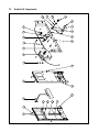
7.2 Basket Lift Components ..................................................................................................7-2
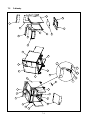
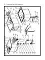
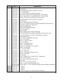
7.3 Cabinetry..........................................................................................................................7-4
7.4 Cookpot and Rinse Tank Components ............................................................................7-6
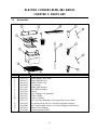
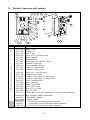
7.5 Electrical Components and Controllers............................................................................7.8
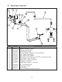
7.6 Water Supply Components..............................................................................................7-9

1-1
ELECTRIC COOKERS 8SMS, 8BC AND 8C
CHAPTER 1: GENERAL INFORMATION
1.1 Parts Ordering and Service Information
In order to assist you as quickly as possible, the Frymaster Factory Authorized Service Center
(FASC) or Service Department representative requires certain information about your equipment.
Most of this information is printed on a data plate affixed to the inside of the door.
Parts orders may be placed directly with your local FASC or distributor. Included with cookers
when shipped from the factory is a list of FASCs. If you do not have access to this list, contact the
Frymaster Technical Service Department at 1-800-551-8633 or 1-318-865-1711.
When ordering parts, the following information is required:
Model Number:
Serial Number:
Voltage:
Item Part Number:
Quantity Needed:
Service information may be obtained by contacting your local FASC/Distributor. Information may
also be obtained by calling the Frymaster Technical Service Department at 1-800-551-8633 or
1-318-865-1711. When requesting service, please have the following information ready:
Model Number:
Serial Number:
Voltage:
In addition to the model number, serial number, and voltage, please be prepared to describe the
nature of the problem and have ready any other information that you think may be helpful in
solving your problem.
RETAIN AND STORE THIS MANUAL IN A SAFE PLACE FOR FUTURE USE.
1.2 Safety Information
Before attempting to operate your unit, read the instructions in this manual thoroughly.
Throughout this manual, you will find safety notations enclosed in boxes similar to the ones
illustrated below and on the following page.
CAUTION
CAUTION boxes contain information about actions or conditions that may cause or result
in malfunction of your equipment.

1-2
WARNING
WARNING boxes contain information about actions or conditions that may cause or
result in damage to your equipment, and which may cause your equipment to
malfunction.
DANGER
DANGER boxes contain information about actions or conditions that may cause or result
in injury to personnel, and which may cause damage or malfunctioning of your
equipment
1.3 Equipment Description
Frymaster Electric Cookers are specifically designed to deliver high volumes of cooked or blanched
food automatically.
Model Comparison:
8SMS: The “Spaghetti Magic System” features an 8-kilowatt cooker and rinse tank
combination. The 8.7-gallon (33-liter) cooker is equipped with a programmable computer
that controls water temperature, water level, and cooking times. A swing-away water faucet
is standard. Its automatic basket lift system submerges and extracts either bulk or
individualized portions of pasta according to times programmed by the operator. Options
include automatic water filling (AutoFill) and starch skimming (AutoSkim). The AutoFill
feature maintains the cookpot water level approximately 1¼ inch (32mm) below the
overflow drain. The AutoSkim feature sprays water onto the surface of the water, forcing
starch to the overflow drain. This eliminates loss of cooking time associated with removing
excess starch buildup. It also keeps the cooking water at the optimum level by replacing
water evaporated during the cooking process. The AutoSkim function also saves energy
since there is no need to reheat a refilled cookpot. The cookpot is safeguarded against over
filling and boilover by a large overflow drain. “SD” following the model designation
indicates a stainless steel cookpot and door, and an enameled cabinet. “SC” following the
model designation indicates all stainless steel components.
8BC & 8C: These standalone cookers are essentially the same as the 8SMS, but without
the built-in rinse tank. 8BC models have an automatic basket lift and optional automatic
water filling and starch skimming. 8C models have no basket lifts and no automatic water
filling and starch skimming options. The cookpot in both is safeguarded against over filling
and boilover by a large overflow drain. “SD” following the model designation indicates a
stainless steel cookpot and door, and an enameled cabinet. “SC” following the model
designation indicates all stainless steel componentes.
1.4 Installation, Operating, and Service Personnel
Operating information for Frymaster equipment is intended for use by qualified and/or authorized
personnel only, as defined in Section 1.5.
All installation and service on Frymaster equipment must be performed by qualified, certi-
fied, licensed, and or/authorized installation or service personnel, as defined in Section 1.5.

1-3
1.5 Definitions
QUALIFIED AND/OR AUTHORIZED OPERATING PERSONNEL
Qualified/authorized operating personnel are those who have carefully read the information in this
manual and have familiarized themselves with the equipment functions, or who have had previous
experience with the operation of the equipment covered in this manual.
QUALIFIED INSTALLATION PERSONNEL
Qualified installation personnel are individuals, or firms, corporations, or companies that, either in
person or through a representative, are engaged in and are responsible for the installation of
electrical appliances. Qualified personnel must be experienced in such work, be familiar with all
electrical precautions involved, and have complied with all requirements of applicable national and
local codes.
QUALIFIED SERVICE PERSONNEL
Qualified service personnel are those who are familiar with Frymaster equipment and who are
authorized by Frymaster to perform service on Frymaster equipment. All authorized service
personnel are required to maintain a complete set of service and parts manuals and to stock a
prescribed minimum amount of Frymaster parts. Failure to use qualified service personnel will
void the Frymaster Warranty on your equipment. A list of Frymaster Factory Authorized Service
Centers (FASCs) is included with the equipment when it is shipped from the factory.
1.6 Shipping Damage Claim Procedure
Your Frymaster equipment was carefully inspected and packed before leaving the factory. The
transportation company assumes full responsibility for safe delivery upon acceptance of the equip-
ment for transport.
What to do if your equipment arrives damaged:
1. File a claim for damages immediately, regardless of the extent of damages.
2. Inspect for and record all visible loss or damage and ensure that this information is noted on
the freight bill or express receipt and is signed by the person making the delivery.
3. Concealed loss or damage that was unnoticed until the equipment was unpacked should be
recorded and reported to the freight company or carrier immediately upon discovery. A
concealed damage claim must be submitted within 15 days of the date of delivery. Ensure that
the shipping container is retained for inspection.
FRYMASTER DOES NOT ASSUME RESPONSIBILITY
FOR DAMAGE OR LOSS INCURRED IN TRANSIT.

2-1
ELECTRIC COOKERS 8SMS, 8BC AND 8C
CHAPTER 2: INSTALLATION INSTRUCTIONS
2.1 General Installation Requirements
PROPER INSTALLATION IS ESSENTIAL FOR EFFICIENT, TROUBLE-FREE
OPERATION OF YOUR COOKER. ANY UNAUTHORIZED ALTERATIONS MADE TO
THIS EQUIPMENT WILL VOID THE FRYMASTER WARRANTY.
Upon arrival, inspect the equipment carefully for visible or concealed damage. (See Shipping
Damage Claim Procedure in Chapter 1.)
NATIONAL CODE REQUIREMENTS
This equipment is to be installed in compliance with the Basic Plumbing Code of the Building
Officials and Code Administrators International, Inc. (BOCA) and the Food Service Sanitation
Manual of the U.S. Food and Drug Administration.
ELECTRICAL GROUNDING REQUIREMENTS
All electrically operated appliances must be grounded in accordance with all applicable national and
local codes. A wiring diagram is located on the inside of the equipment door. Refer to the rating
plate on the inside of the door for proper voltages.
FCC COMPLIANCE
The user is cautioned that any changes or modifications to Frymaster computers not expressly
approved by the party responsible for compliance could void the user’s authority to operate the
equipment. Frymaster computers have been tested and found to comply with the limits for a Class A
digital device, pursuant to Part 15 of the FCC rules. While these devices are verified as Class A
devices, they have been shown to meet the Class B limits. These limits are designed to provide
reasonable protection against harmful interference when the equipment is operated in a commercial
environment. This equipment generates, uses, and can radiate radio frequency energy and, if not
installed and used in accordance with the instruction manual, may cause harmful interference to
radio communications. Operation of the equipment in a residential area is likely to cause harmful
interference in which case the user will be required to correct the interference at his own expense.
If necessary, the user should consult the dealer or an experienced radio and television technician for
additional suggestions.
The user may find the booklet “How to Identify and Resolve Radio-TV Interference Problems”
helpful. It is prepared by the Federal Communications Commission and is available from the U.S.
Government Printing Office, Washington, DC 20402, Stock No. 004-000-00345-4.

2-2
2.2 Caster/Leg Installation
Depending upon the specific configuration ordered, your unit might have been shipped without in-
stalled casters or legs. If casters or legs are installed, you may skip this section and proceed to Sec-
tion 2.3, Pre-Connection Preparations.
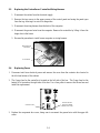
If your unit requires the installation of casters/legs, install them in accordance with the in-
structions included in your accessory package.
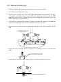
2.3 Pre-Connection Preparations
After the unit has been positioned in the area where it will be used, ensure the following have been
accomplished before connecting the unit to the electrical power source:
1. This equipment must be stabilized by installing restraining chains on units equipped with
casters or anchor straps on units equipped with legs. Follow the instructions shipped with
the casters/legs to properly install the chains or straps.
2. Level units equipped with legs by screwing the legs out approximately 1 inch, then adjusting
them so that the unit is level.
For units equipped with casters, there are no built-in leveling devices. The floor where the
unit is to be installed must be level.
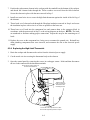
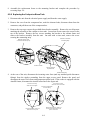
3. Install the basket lift arm (on units so equipped) on the lift rod (located at the top rear of the
cabinet) so that the basket lift roller guides the lift arm.
NOTE: Some adjustment of the roller may be necessary for free movement of the basket lift
arm.
4. Connect the water hose to the fitting at the rear of the unit.
DANGER
The maximum allowable incoming water pressure for all units is 80 PSI (5.6 kg/cm
2
)
(551.6 kPa).
The maximum allowable incoming water temperature for all units is 180ºF (82ºC).
NOTE: Either hot or cold water may be connected to the unit. However, connecting hot
water will minimize the time required to bring the unit to boil when filling with fresh water.
NOTE: In order for the water level sensors to work properly, a certain amount of mineral
content in necessary in the water. For that reason, purified, deionized, or highly filtered wa-
ter should not be used.
5. Connect the desired drain plumbing to the drain valve.

2-3
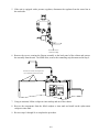
2.4 Connecting to the Electrical Power Supply
DANGER
This unit must be connected to the voltage and phase specified on the rating and serial
number plate located on the inside of the equipment door. To determine the appropriate
wire size, refer to the POWER REQUIREMENTS chart at the bottom of this page.
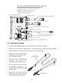
1. If the unit is not equipped with an installed power cord, open the door and remove the contactor
box cover. Position the unit to gain access to the rear and remove the lower back panel.
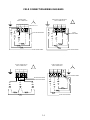
2. Insert an appropriately rated power cord into the rear of the contactor box and make connections
in accordance with the applicable wiring diagram on the following page. Install a strain relief on
the power cord and replace the lower back panel and contactor box cover.
3. Attach a plug that complies with national and/or applicable local codes to the free end of the
electrical power cord and plug the unit into an appropriate outlet.
POWER REQUIREMENTS
Use copper wire ONLY, suitable for at least 170ºF (75ºC)
Volts Phase Watts
Amps
(per leg)
Minimum
Wire Size
200 Single 7400 37 AWG 6 (4.1 mm)
208 Single 8000 39 AWG 6 (4.1 mm)
220 Single 7300 34 AWG 6 (4.1 mm)
230 Single 8000 35 AWG 6 (4.1 mm)
240 Single 8000 34 AWG 6 (4.1 mm)
200 3P – Delta 7400 22 AWG 8 (3.3 mm)
208 3P – Delta 8000 23 AWG 8 (3.3 mm)
220 3P – Delta 7300 20 AWG 8 (3.3 mm)
230 3P – Delta 8000 21 AWG 8 (3.3 mm)
240 3P – Delta 8000 20 AWG 8 (3.3 mm)
200 3P – Wye 7400 13 AWG 8 (3.3 mm)
220 3P – Wye 7300 12 AWG 8 (3.3 mm)
230 3P – Wye 7400 11 AWG 8 (3.3 mm)
NOTE: This equipment is field-convertible between single phase and three phase.

2-4
FIELD CONNECTION WIRING DIAGRAMS
SINGLE PHASE (NO NEUTRAL)
FIELD CONNECTION
L1
L2 L3
1
1HV
1C1
2HV
1C2
2
3
3HV
1C3
4
5
6
FROM TRANSFORMER
FROM
TRANSFORMER
3 PHASE 4 WIRE (WYE)
FIELD CONNECTION
L1
L2 L3
N
1HV
1C1
2HV
1C2
3HV
1C3
1
2
3
4
5
6
FROM TRANSFORMER
FROM TRANSFORMER
3 PHASE 3 WIRE (DELTA)
FIELD CONNECTION
L1
L2 L3
1HV
1C1
12
53
2HV
1C2
3HV
1C3
46
FROM TRANSFORMER
FROM TRANSFORMER
SINGLE PHASE
FIELD CONNECTION
NEUTRAL TO L3
L1
L2 L3
1
1HV
1C1
2HV
1C2
2
3
3HV
1C3
4
5
6
FROM TRANSFORMER
FROM TRANSFORMER

3-1
ELECTRIC COOKERS 8SMS, 8BC AND 8C
CHAPTER 3: OPERATING INSTRUCTIONS
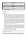
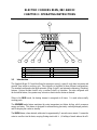
1
6
5432 7
8 9
1 Numeric Keypad 6 Skim Switch (w/Autoskim only)
2 Boil Mode Indicator 7 Timer Start Switch
3 Boil Mode Switch 8 Simmer Mode Switch
4 Power Switch 9 Simmer Mode Indicator
5 LED Display
3.1 Introduction
The Spaghetti Magic II Controller allows the operator to specify a specific cook time in minutes and
seconds, then initiate a cooking cycle. This controller is available in three different configurations.
The standard configuration has both automatic filling (Autofill) and automatic skimming (Autoskim)
features. Options include Autofill only, or neither Autofill or Autoskim. On units configured with
the Autoskim feature, the operator may activate or deactivate the feature as desired.
When in the BOIL mode, the heating element is energized at all times. It is used when actually
cooking pasta.
The SIMMER mode feature maintains the water temperature just below boiling, which conserves
energy and water. This feature is designed for rethermalizing previously cooked packaged products,
and for keeping the cooker in standby.
The SKIM feature, when selected, adds water for approximately 3 seconds once a minute. It causes the
water to overflow into the drain, carrying floating starch with it. (A buildup of starch reduces the effi-

3-2
ciency of the cooker and can cause erroneous temperature and water level sensing. NOTE: Do not use
deliming solution to clean these units. Use of deliming solution will damage all stainless steel parts.)
LOW WATER SENSING automatically de-energizes the heating element if the water in the cook-
pot drops too low. When the water level in the cookpot is below the low-water sensor, such as when
draining and cleaning the cookpot, the controller display will read LO.
NORMAL WATER LEVEL SENSING, on units configured with the Autofill feature, automatically
adds water during or after a cooking cycle if the water in the cookpot drops to a level lower than ap-
proximately 1¼ inch (32mm) below the overflow drain. With this automatic filling feature, the water
level does not have to be continuously monitored. The cookpot always has the correct amount of water.
3.2 Operating Instructions
Before turning the cooker on, ensure that:
• the unit is connected to the water supply.
• the water supply is turned on.
• the unit is plugged into an appropriate outlet.
• the electrical power supply is turned on.
CAUTION
If this is the first time the unit is being used after installation, refer to Section 3.4, Boiling
Out the Cookpot.
1. Turn the controller on by pressing the Power switch.
2. The unit will automatically enter the boil mode and the boil mode indicator will illuminate. If
you do not intend to immediately begin cooking, press the Simmer Mode switch. The sim-
mer mode indicator will illuminate. To re-enter the boil mode, press the Boil Mode switch.
3. Enter the desired cooking time using the numeric keypad. The time entered appears in the LED
display.
4. When ready to initiate a cooking cycle, press the Start Timer
switch. The basket lift will
automatically lower the basket or portion cups into the cookpot and the LED display will begin
to count down. At the end of the cooking cycle, an alarm will sound briefly to alert you and the
basket lift will automatically raise the basket or portion cups out of the water.
The display will automatically return to the previously set cooking time. If the same time is de-
sired for the next batch, simply press the Start Timer switch when ready, otherwise enter the
new cooking time before pressing the switch.
5. To initiate the automatic skimming (Autoskim) feature, press the Skim
switch.

3-3
3.3 Toggling Between Fahrenheit and Celsius Temperature Display
There are two versions of the SMS Controller: one that can be toggled between Fahrenheit and
Celsius temperature display, and one that cannot. To determine which version you have, turn the
controller off by pressing the ON/OFF switch. The display will go blank. Press the Simmer (right
thermometer icon) switch. If Code appears in the display, the temperature display can be changed.
If not, the display cannot be changed.
1. If Code appears in the display, press 1, 6, 5, 8. The display will be toggled from Fahrenheit to
Celsius or from Celsius to Fahrenheit.
2. Press the Boil (left thermometer icon) switch to display the cookpot temperature. If an F follows
the temperature, the display is in Fahrenheit; if a C follows the temperature, the display is in
Celsius.
3.4 Shutting the Cooker Down
Turn the unit off by pressing the Power switch. If shutting down at the end of the day, drain and
clean the cookpot (and rinse tank, if so equipped), and put the cookpot and rinse tank covers in
place.
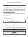
3.5 Boiling Out the Cookpot
To ensure that the cooker is free of contamination from manufacture, shipping, or handling during
installation, the cookpot must be boiled out before first use.
1. Close the drain valve and fill the cookpot with a solution of cold water and 1 cup of detergent.
2. Place the unit into operation (see Section 3.2).
3. Press the simmer switch
and allow the solution to simmer for at least 1 hour.
4. After the solution simmers for 1 hour, turn the unit off and add cold water until the solution is
cool. Drain the solution and clean the cookpot thoroughly with a solution of dishwashing deter-
gent and hot water.
NOTE: Do not use deliming solution to clean these units. Use of deliming solution will damage
all stainless steel parts.
WARNING
When cleaning around the elements, be careful not to bend or otherwise damage the high-
limit thermostat capillary tube.
5. Rinse the cookpot at least twice by filling with clean water and draining. Dry the cookpot thor-
oughly with a clean, dry towel.
6. For units equipped with a rinse tank, clean the tank with a solution of dishwashing detergent and
hot water. Drain the tank and dry it thoroughly with a clean, dry towel.

4-1
ELECTRIC COOKERS 8SMS, 8BC AND 8C
CHAPTER 4: PREVENTIVE MAINTENANCE
4.1 Daily Preventive Maintenance
It is normal for a coating of starch to form on the elements, sensors, and temperature probes during
operation. If the coating is allowed to build-up, it will adversely affect the operation of the
equipment. The preventive maintenance routines below should be performed at least daily to keep
your equipment functioning at peak efficiency. The cookpot and rinse tank – especially the water-
level sensors, temperature probe, and element – may require more frequent cleaning, depending
upon the product and volume. NOTE: Do not use deliming solution to clean these units. Use of
deliming solution will damage all stainless steel parts.
Inspect Equipment and Accessories for Damage
Look for loose or frayed wires and cords, leaks, foreign material in cookpot or inside cabinet,
and any other indications that the equipment and accessories are not ready for safe operation.
Clean Cabinet Inside and Out
Clean inside the cabinet with a dry, clean cloth. Wipe all accessible metal surfaces and
components to remove accumulations of oil, dust, or cooking residue.
Clean the outside of the cabinet with a clean cloth dampened with dishwashing detergent,
removing oil, dust, or cooking residue.
DANGER
Never attempt to clean this equipment during the cooking process or when the
cookpot is filled with hot water and/or food products.
Clean Water-Level Sensors, Temperature Probe, Element, Cookpot, and Rinse Tank
Turn the equipment off and drain the cookpot (and rinse tank, if so equipped).
Remove the probe cover and clean the water-level sensors and temperature probe using a
Scotchbrite™ or similar abrasive pad and a solution of detergent and water.
Using a Scotchbrite™ or similar abrasive pad and a solution of detergent and water, clean the inside
of the cookpot (and rinse tank, if so equipped). Pay particular attention to the heating element.
Rinse the cookpot (and rinse tank, if so equipped) thoroughly with clean water at least twice.
WARNING
Do not use deliming solution to clean these units. Use of deliming solution will
damage all stainless steel parts.
WARNING
When cleaning around the element, be careful not to bend or otherwise damage the
high-limit thermostat capillary tube.

4-2
4.2 SMS II Controller Simmer Mode Adjustment
NOTE: The SMS II Controller simmer temperature is adjustable from 185ºF to 215ºF.
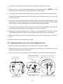
1. With the unit in the simmer mode, place the tip of a good grade thermometer near the
temperature probe and determine the actual water temperature in degrees Fahrenheit. If the
temperature is within 5ºF of the desired simmer temperature, nothing more needs to be done. If
it is not within 5ºF of the desired temperature, perform Steps 2 through 5.
2. With the unit in the simmer mode, open the control panel by removing the screws in the upper
corners and tilting the panel out.
3. Remove the black rubber plug from the top of the controller housing.
4. Using a small, flat-tipped screwdriver, turn the adjusting screw to change the simmer setpoint.
¼ turn will change the setpoint about 10ºF. (You will have to experiment with the direction of
rotation to determine which way to turn to raise or lower the temperature.) Wait at least 5
minutes, then recheck actual water temperature. Repeat this step until the water temperature is
within 5ºF of desired temperature.
5. Replace the plug in the controller, close the control panel, and replace the screws removed in
Step 1.

5-1
ELECTRIC COOKERS 8SMS, 8BC AND 8C
CHAPTER 5: OPERATOR TROUBLESHOOTING
5.1 Introduction
This chapter provides an easy reference guide to the more common problems that may occur during
the operation of this equipment. The troubleshooting guides in this chapter are intended to help you
correct, or at least accurately diagnose, problems with the equipment. Although the chapter covers
the most common problems reported, you may very well encounter a problem not covered. In such
instances, the Frymaster Technical Service Department will make every effort to help you identify
and resolve the problem.
When troubleshooting a problem, always use a process of elimination starting with the simplest
solution and working through to the most complex. Never overlook the obvious. Anyone can forget
to plug a cord into a receptacle or open the valve on the water supply line. Don’t assume that you
are exempt from such occurrences. Most importantly, try to establish a clear idea of why a problem
has occurred. Part of your corrective action involves taking steps to ensure that it doesn’t happen
again. If a controller malfunctions because of a poor connection, check all other connections while
you’re at it. If a fuse continues to blow, find out why. Keep in mind that failure of a small
component may often be indicative of potential failure or incorrect functioning of a more important
component or system.
Some of the troubleshooting actions recommended in this chapter involve removing suspect
controllers and substituting controllers that are known to be good. Whenever this is indicated, refer
to Section 5.3. Refer to Section 5.4 for instructions on replacing fuses.
If you have doubts as to the proper action to take, do not hesitate to call the Frymaster Technical
Service Department or your local Frymaster Factory Authorized Service Center for assistance.
Before calling a servicer or the Frymaster HOTLINE (1-800-551-8633):
• Verify that electrical cords are plugged in and that circuit breakers are on.
• Verify that water supply valves are open and that drain valves are fully closed.
DANGER
Hot water can cause severe burns. Never attempt to move a cooker containing hot
water or to transfer hot water from one container to another.
DANGER
Use extreme care when performing electrical circuit tests. Live circuits will be
exposed.
WARNING
Inspection, testing, and repair of electrical components should be performed only by
qualified service personnel. The equipment should be unplugged when servicing,
except when electrical tests are required.
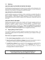
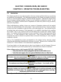
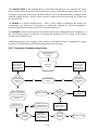
5.2 Operator Troubleshooting Guides

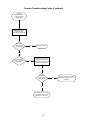
5-2
ON UNIT WITH AUTOFILL,
COOKPOT DID NOT FILL
WHEN UNIT WAS
TURNED ON. WATER
SUPPLY TO UNIT
VERIFIED TO BE ON.
Did anything
appear in controller
display when unit was
turned on?
Disconnect unit from
electrical power. Check
the left 5-amp fuse in
component box. Replace
fuse if blown then attempt
to operate.
Did unit begin
to fill?
Probable causes are shorted
upper water level sensor, failed
water solenoid, or loose/
damaged wiring. Call FASC.
No
No
NOTE: IF AUTOFILL WORKS
BUT AUTOSKIM DOES NOT,
PROBLEM IS A FAILED
CONTROLLER. ORDER
REPLACEMENT FROM FASC
OR DISTRIBUTOR.
Clean the water
level sensors.
Is another
controller, known
to be working,
available?
Substitute the controller
known to be working for
the suspect controller and
attempt to operate unit.
Yes
No
Problem resolved.Yes
Yes
Yes
Problem is beyond
the scope of operator
troubleshooting. Call
FASC.
No
No
Problem is a failed
controller. Order
replacement from
FASC or distributor.
Yes
Did unit begin
to fill?
Did unit begin
to fill?

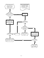
5-3
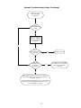
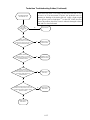
Operator Troubleshooting Guides (Continued)
ON UNIT WITH
AUTOFILL, WATER DID
NOT SHUT OFF WHEN
COOKPOT WAS FULL.
Clean the water
level sensors.
Did the water
stop?
Yes
Problem resolved.
Add 1/8-cup of
baking soda to the
water in the
cookpot and stir.
Did the water
stop?
Mineral content of water is
insufficient for water sensor to
ground. Whenever cookpot is
refilled, add 1/8-cup of
baking soda.
Probable causes are a loose or
damaged wire on the upper water
level sensor, a failed water solenoid,
or a failed upper water level sensor.
Call FASC.
Yes
No
No
Page is loading ...
Page is loading ...
Page is loading ...
Page is loading ...
Page is loading ...
Page is loading ...
Page is loading ...
Page is loading ...
Page is loading ...
Page is loading ...
Page is loading ...
Page is loading ...
Page is loading ...
Page is loading ...
Page is loading ...
Page is loading ...
Page is loading ...
Page is loading ...
Page is loading ...
Page is loading ...
Page is loading ...
Page is loading ...
Page is loading ...
Page is loading ...
Page is loading ...
Page is loading ...
Page is loading ...
Page is loading ...
Page is loading ...
Page is loading ...
Page is loading ...
Page is loading ...
Page is loading ...
Page is loading ...
-
 1
1
-
 2
2
-
 3
3
-
 4
4
-
 5
5
-
 6
6
-
 7
7
-
 8
8
-
 9
9
-
 10
10
-
 11
11
-
 12
12
-
 13
13
-
 14
14
-
 15
15
-
 16
16
-
 17
17
-
 18
18
-
 19
19
-
 20
20
-
 21
21
-
 22
22
-
 23
23
-
 24
24
-
 25
25
-
 26
26
-
 27
27
-
 28
28
-
 29
29
-
 30
30
-
 31
31
-
 32
32
-
 33
33
-
 34
34
-
 35
35
-
 36
36
-
 37
37
-
 38
38
-
 39
39
-
 40
40
-
 41
41
-
 42
42
-
 43
43
-
 44
44
-
 45
45
-
 46
46
-
 47
47
-
 48
48
-
 49
49
-
 50
50
-
 51
51
-
 52
52
-
 53
53
-
 54
54


Frymaster 8SMS User manual
- Category
- Pressure cookers
- Type
- User manual
Ask a question and I''ll find the answer in the document
Finding information in a document is now easier with AI
Related papers
-
Frymaster 8SMS User manual
-
 Frymaster Pasta Magic Electric 8/17SMS-8/17BC-8/17C Owner's manual
-
 Frymaster 17-8SMS Magic Electric Cooker User manual
-
Frymaster 17ECS User manual
-
 Frymaster Pasta Magic 17BC User manual
-
 Frymaster Pasta Magic Operating instructions
-
Frymaster GC User manual
-
 Frymaster Pasta Magic Operational Manual
-
-
 Frymaster PHD User manual


Other documents
-
Hans Grohe Axor 35002801 User manual
-
Henny Penny EIGHT HEAD COOKERS 680 User manual
-
Delta 400LF-HDF Installation guide
-
Henny Penny 581 Operating instructions
-
-
Pitco Frialator PPE14-L Operating instructions
-
-
Fanimation Palmetto Mtr-End Expl-V Owner's manual
-
Hubbell PCORE Quick-Link Bushings Operating instructions
-