Comelit 49134 User manual
- Category
- Digital Video Recorders (DVR)
- Type
- User manual

1
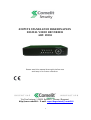
4 INPUTS STANDALONE H264 HEXAPLEX
DIGITAL VIDEO RECORDER
ART. 49134
Please read this manual thoroughly before use
and keep it for future reference.
Via Don Arrigoni, 5 24020 Rovetta S. Lorenzo (Bergamo)
http://www.comelit.it – E mail: export.de[email protected]t

2
WARNING
TO REDUCE THE RISK OF FIRE OR ELECTRIC SHOCK, DO NOT EXPOSE THIS PRODUCT TO RAIN OR
MOISTURE. DO NOT INSERT ANY METALLIC OBJECT THROUGH THE VENTILATION GRILLS OR OTHER
OPENINGS ON THE EQUIPMENT.
CAUTION
Explanation of graphical symbols
The lightning flash with arrowhead symbol, within an equilateral triangle, is
intended to alert the user to the presence of uninsulated “dangerous voltage”
within the product’s enclosure that may be of sufficient magnitude to constitute a
risk of electric shock to person.
The exclamation point within an equilateral triangle is intended to alert the user to
the presence of important operating and maintenance (servicing) instructions in
the literature accompanying the product.
The user is obliged to inform himself and to conform himself to the national and local rules concerning the
monitoring and the audio and video recording. Nobody else will consequently be held responsible for an
improper use of this system which could break the laws in force.

3
FCC COMPLIANCE STATEMENT
FCC INFORMATIONS: THIS EQUIPMENT HAS BEEN TESTED AND FOUND TO COMPLY WITH THE
LIMITS FOR CLASS A DIGITAL DEVICE, PURSUANT TO PART 15 OF THE FCC RULES. THESE LIMITS
ARE DESIGNED TO PROVIDE REASONABLE PROTECTION AGAINST HARMFUL INTERFERENCE IN A
RESIDENTIAL INSTALLATION. THIS EQUIPMENT GENERATES, USE AND CAN RADIATE RADIO
FREQUENCY ENERGY AND, IF NOT ISTALLED AND USED IN ACCORDANCE WITH THE
INSTRUCTIONS, MAY CAUSE HARMFUL INTERFERENCE TO RADIO COMMUNICATIONS. HOWEVER,
THERE IS NO GUARANTEE THAT INTERFERENCE WILL NOT OCCUR IN A PARTICULAR
INSTALLATION. IF THIS EQUIPMENT DOES CAUSE HARMFUL INTERFERENCE TO RADIO OR
TELEVISION RECEPTION, THE USER IS ENCOURAGED TO CORRECT THE INTERFERENCE TO OWN
EXPENSES.
CAUTION: CHANGES OR MODIFICATIONS NOT EXPRESSLY APPROVED BY THE PARTY
RESPONSIBLE FOR COMPLIANCE COULD VOID THE USER’S AUTHORITY TO OPERATE THE
EQUIPMENT.
THIS CLASS A DIGITAL DEVICE COMPLIES WITH CANADIAN RULES.
CE COMPLIANCE STATEMENT
CE COMPLIANCE STATEMENTCE COMPLIANCE STATEMENT
CE COMPLIANCE STATEMENT
WARNING:
THIS IS A CLASS A DIGITAL DEVICE. IN A DOMESTIC ENVIRONMENT THIS PRODUCT MAY CAUSE
RADIO INTERFERENCE, IN WHICH CASE THE USER MAY BE REQUIRED TO TAKE ADEQUATE
MEASURES.

4
IMPORTANT SAFEGUARDS
1. READ AND KEEP THESE INSTRUCTIONS
Please read this manual thoroughly before use and keep it for future reference.
2. CLEANING
Unplug this equipment from the wall outlet before cleaning it. Use a mild household detergent, never use strong solvent. Clean the
unit with a slightly damp soft cloth.
3. ATTACHMENTS
Never add any attachments and/or equipment without the approval of the manufacturer as such additions may result in the risk of fire,
electric shock or other personal injury.
4. WATER AND/OR MOISTURE
Do not use this equipment near water or in contact with water.
5. ACCESSORIES
Do not place this equipment on an instable cart, stand or table. The equipment may fall, causing serious injury to a child or adult, and
serious damage to the equipment. Wall or shelf mounting should follow the manufacturer’s instructions and shoul use a mounting kit
approved by the manufacturer. This equipment and cart combination should be moved with care. Quick stops, excessive force and
uneven surfaces may cause the equipment and cart combination to overturn.
6. VENTILATION
If existing, the openings or ventilation grills of the device have been planned with the scope to supply ventilation to the apparatus, to
assure a reliable operation of the same and to protect it from overheating. Do not block or cover these openings.
7. POWER SOURCES
This equipment should be operate only from the type of power source indicated on the marking label. If you are not sure of the type of
power, please consult your equipment dealer or local power company. Warning if this equipment works with battery, risk of explosion if
battery is replaced by an incorrect type. Dispose of used batteries according to the local law.
8. GROUNDING
Do not defeat the safety purpose of the polarized or grounding-type plug. A polarized plug has two blades with one wider that the other.
A grounding type plug has two blades and a third grounding prong. The wider blade or the third prong are provided for your safety. If
the provided plug does not fit into your outlet, consult an electrician for replacement of the obsolete outlet.
9. POWER AND CONNECTION CABLES PROTECTION
Protect the cables from being walked on or pinched particularly at plugs and the point where thy exit from the equipment.
10. LIGHTNING STORM
For added protection for this equipment during a lightning storm or when it is left unattended and unused for long periods of time,
unplug it from the wall outlet and disconnect the antenna or cable system. This will prevent damage to the equipment due to lightning
and power line surges.
11. OVERLOADING
Do not overload wall outlets and extension cords as this can result in the risk of fire or electric shock.
12. SERVICING
Do not attempt to repair this equipment yourself. The opening and the movement of the covers could you expose at high voltage or
other dangers. Refer all servicing to qualified service personnel.
13. DAMAGE REQUIRING SERVICE
Unplug this equipment from the wall outlet and refer servicing to qualified personnel under the following conditions:
a. If the power supply cord or the plug has been damaged.
b. If liquid is spilled or objects have fallen into the equipment.
c. If the equipment has been exposed to rain or water.
d. If the equipment does not operate normally by following the operating instructions. Adjust only those controls that are covered by
operating instructions. An improper adjustment of other controls may result in damage.
e. If the equipment has been dropped or the case damaged.
f. If the equipment exhibits a distinct change in performance.
14. REPLACEMENT PARTS
When replacement parts are required, be sure the service technician has used replacement parts specified by the manufacturer or that
have the same characteristics as the original part. Unauthorized substitutions may results in fire, electric shock or other hazards.
15. SAFETY CHECK
Upon completation of any service or repairs to this equipment, ask the service technician to perform safety checks to determine that
the equipment is in proper operating condition.
16. INSTALLATION IN PUBLIC PLACES
This kind of installation would have to be made by specialized personnel and to be in compliance with the local laws.

5
Table of Contents
1. Product Overview
·································································································
1.1 Features············································································································
2. Panels And Remote Controller············································································
2.1 Front Panel·······································································································
2.2 Back Panel········································································································
2.3 Remote Controller····························································································
3. Installations···········································································································
3.1 Basic Connections····························································································
3.2 Optional Connections·······················································································
4. Main Screen And Basic Operations····································································
4.1 Text Input·········································································································
4.2 Login And Logout····························································································
4.3 Basic Operations······························································································
4.4 Digital Zoom····································································································
5. Menu Display
········································································································
5.1 Status Display···································································································
5.2 Video Adjustment·····························································································
5.3 VGA Display····································································································
5.4 Backup Device·································································································
5.5 Software Upgrade (Administrator) ·································································
5.6 System Shutdown (Administrator) ··································································
6. Setup (Administrator) ·························································································
6.1 Pre-Camera Setup····························································································
6.2 Camera Setup···································································································
6.2.1 Video Loss Setup·····················································································
6.2.2 Motion Setup····························································································
6.3 Alarm Setup······································································································
6.4 SEQ Display Setup···························································································
6.5 Scheduled Record Setup··················································································
6.6 HDD Setup·······································································································
6.6.1 HDD Format/Clear···················································································
6.7 Password Setup································································································
6.8 System Setup····································································································
6.9 RS-232/422/485 Setup·····················································································
6.10 Network Setup································································································
6.10.1 E-mail Setup···························································································
7
7
8
8
10
12
12
12
14
15
16
17
17
19
20
20
21
22
22
25
26
26
27
28
30
31
34
35
37
38
39
41
42
43
44
46

6
6.10.2 Advanced Network Setup······································································
7. PTZ Control··········································································································
8. Search/Playback/Archive (Administrator/Supervisor) ····································
8.1 Search By Time································································································
8.2 Search By Event / Log Display········································································
8.3 Search Archived Files······················································································
8.4 Playback/Archive For Search By Time····························································
8.5 Playback/Archive For Search By Event···························································
8.6 Playback For Archived Files············································································
9. Remote Access·······································································································
10. PDA/Mobile Phone Remote Access···································································
Appendix A--MS-Windows HEM player···································································
Appendix B--The mouse operation interface reference··············································
Appendix C--Specifications························································································
Appendix D--Recording Table····················································································
47
48
49
50
51
52
53
55
55
55
62
63
65
68
70

7
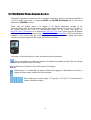
1. Product Overview
The H.264 digital video/audio recorders are designed for a surveillance system and are a
combination of a hard disk recorder, a video multiplexer and a web server. To achieve the highest
inter-connectivity and inter-operability, this series of digital video/audio recorders are all based on
industry-leading front-end to back-end surveillance infrastructure. With state-of-the-art system
architecture, powerful compression/decompression engine and intelligent recording algorithms,
sixfold operation can be easily achieved without sacrificing the increasing demands of functionality,
performance, reliability and availability in the surveillance industry.
1.1 Features
Up to 4 color and/or B/W cameras can be connected
H.264 Baseline Profile video compression/decompression with configurable quality
ADPCM audio compression/decompression
Real sixfold operation - simultaneous record, live, playback, backup, control & remote access
Record capabilities –
Full-D1: up to 30 (NTSC) / 25 (PAL) IPS (Images Per Second)
Half-D1: up to 60 (NTSC) / 50 (PAL) IPS
CIF: up to 120 (NTSC) / 100 (PAL) IPS
Playback capabilities –
Full-D1: up to 30 (NTSC) / 25 (PAL) IPS
Half-D1: up to 60 (NTSC) / 50 (PAL) IPS
CIF: up to 120 (NTSC) / 100 (PAL) IPS
Realtime live display, 30 (NTSC) / 25 (PAL) IPS for each channel
Event recording, time-lapse recording or both
Playback search by time or event (alarm, motion & video loss)
Versatile display formats: full-screen and 4 quad
Digital zoom, X2 & X4
Intelligent motion detection with programmable area and sensitivity
Powerful alarm processor with configurable triggering conditions and reactions
One 3.5” hard disk drive
Video/audio backup to USB2.0 storage devices, including pen drive, DVD+RW, DVD+R and
DVD-R
Ethernet interface for remote access through web browser, remote alarm notification, remote
setup and remote software upgrade
PTZ control capabilities
Multi-language support
Multi-level password to ensure high degree of security

8
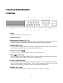
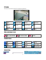
2. Panels and Remote Controller
2.1 Front Panel
1. LEDs
Indicators for POWER and HDD access.
2. Remote IR PORT
5. Alpha-numeric buttons (1-4, *, #)
Press these buttons for camera selection in most of the circumstances. These buttons can also
be used to enter text and number in the way similar to most of the mobile phones.
6. MODE/MARK button
Press this button to toggle between live mode and playback mode in main screen display. In
some dialogs, this button is used as a miscellaneous function key.
8. Play/Pause button ( )
Press this button to play the recorded images or pause the playback.
10. Stop ( ) / PTZ button
Press this button to stop the playback. While not playing in main screen display, press this
button to enter/exit PTZ control if the camera is a PTZ camera.
12. CALL / BACKUP button
Press this button to copy the playback images to the storage device connected to the USB port.
Press this button again to stop copying. In PTZ control, press this button to zoom in the
camera. In some dialogs, this button is used as a miscellaneous function key.
14. MENU / ESC button
Press this button to display the main menu or escape to the upper level display.

9
15. Left/Right buttons (◄,►)
In PTZ control, press these buttons to pan the camera. In playback mode, press these buttons
for fast backward/forward. In the other screens, press these buttons to move the cursor or
focus window.
16. Up button (▲)
Press this button to move the cursor or focus window in most circumstances. In PTZ control,
press this button to tilt up the camera.
17. Down button (▼)
Press this button to move the cursor or focus window in most circumstances. In PTZ control,
press this button to tilt down the camera. In playback mode, press this button for single step.
18. ENTER button
This button is used as “enter” key in most circumstances. In PTZ control, this button is used
to start/stop the selected PTZ control mode.
19. (Split Windows) +/- buttons ( )
In quad display, press these buttons for next/previous quad display. In the others, press these
buttons to change the contents.

10
2.2 Back Panel
1. Video Input Connectors (CH1 - CH4)
Connect system cameras to these BNC connectors.
2. Call Monitor Output Connector (CALL OUT)
Connect CCTV monitor to this BNC connector for call monitor display.
3. Main Monitor Output Connectors (MAIN OUT)
Connect CCTV monitor to the BNC connector for main monitor display.
4. Audio Input Connector (AUDIO IN)
This RCA connector accept line-in audio signals supplied from external devices such as
microphone amplifiers.
5. Audio Output Connector (AUDIO OUT)
This RCA connector supply line-out audio signals to external devices such as speakers.
Recorded audio will be supplied from AUDIO OUT during playback.
6. Main Monitor Output VGA Connector (MAIN OUT VGA)
Connect VGA monitor to the D-SUB 15-pin female connector for main monitor display.
8. RS-485 Connector
Connect this connector to RS-485 compatible PTZ camera(s). Please refer to the manuals come
with the RS-485 compatible devices for the correct settings.
9. Alarm Output Connectors (ALARM OUT 1-2)
Connect these connectors to Normally Closed (NC) alarm output (C-1) and/or Normally Open
(NO) alarm output (C-2).
10. Alarm Input Connectors (ALARM IN 1-4)
Four external devices such as sensors or door switches can be connected. Each alarm input
should have 2 or 3 wires. Those with 2 wires will either be Normally Open (NO) or Normally
Closed (NC). Those with 3 wires will allow the user to choose. Connect one of the two wires to
the port indicated as “G” for ground. Connect the other wire to either port 1, 2, 3 or 4. Direction
does not matter. When the alarm input has been connected, please configure the software system

11
according as per Alarm Setup as described in Section 6.3.
11. Ethernet Connector (LAN)
Connect this DVR to a 10/100Base-T Ethernet network through this port.
13. Power Cord Inlet (DC 12V)
Connect DC 12V-5A power source.
14. USB connector (USB)
Connect to USB 2.0 compatible storage device, such as USB 2.0 disk drive, DVD+RW, card
reader, etc. Please note that the maximum USB current for the DVR is 500mA.
15. Mouse plug port (PS/2)
For mouse connection
16. Power Switch (POWER)
Turn the power of this unit on/off.

12
2.3 Remote Controller
The remote controller is an accessory to ease the user’s operations. You can do all the operations by
the remote controller instead of the buttons on the front panel. The effective distance is about 10
meters without any obstacle.
The Buttons
Each of these buttons corresponds to one of those buttons on the front panel. Please refer to the
descriptions in Section 2.1.
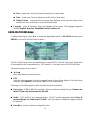
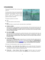
3. Installations
The installations described below should be made by qualified service personnel or system
installers.
3.1 Basic Connections
Please refer to the following diagram for the connections.
Cameras
Connect the camera video input connectors (CH1, CH2, CH3, CH4) to the video outputs from
system cameras or other composite video sources via coaxial cables.

13
Main monitor
Connect the main monitor output connector (BNC) to a surveillance monitor or connect the
VGA output connector to a VGA monitor. The CCTV/VGA monitor displays selected live or
recorded cameras in any available split window format.
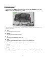
Hard disk drive
Make sure to install one SATA hard disk (Max. storage size 500GB) inside the DVR.
Set the HDD as MASTER!. The steps are as below:
1. Power off the machine and then use a screwdriver to uncover it.
2. Use a screwdriver to fix the SATA HDD (3.5”) as shown.
3. Connect the cable to the HDD.
4. Cover the machine.
Note:
The HDD must be FORMATTED before it can be used to record video/audio. Please
refer to Section 6.6.1 to format the HDD.
Power
Connect DC 12V power source.

14
3.2 Optional Connections
Audio input
Connect the audio input connector to the audio line-out from system cameras or other audio
source. Please make sure to associate the audio input with the camera in Camera Setup as
described in Section 6.2.
Audio output
Connect the audio output connector to the audio line-in of the speakers.
Alarm inputs
Connect the alarm inputs to NC and/or NO type of alarm signals. Please make sure to setup the
alarm configurations as described in Section 6.3.
Alarm outputs
Connect the alarm output #1 to NC type of alarm signal, alarm output #2 to NO type of alarm
signals.
Ethernet
Connect the Ethernet connector to a standard twisted-pair Ethernet cable for remote access via
LAN or internet. Please make sure to setup the related configurations as described in Section
6.10 Network Setup.
USB 2.0 disk drives, DVD+RW, card reader, etc.
If the user wants to use USB2.0 peripheral device to retrieve important recorded images and/or
audio, please connect it to the USB port connector.
I/R remote controller
The user may use I/R remote controller to control the digital video/audio recorder.
Call monitor
Connect the call monitor output connector to a surveillance monitor. This monitor displays the
full screen images of the cameras associated with the events (alarm or motion) or the images
from the installed cameras sequentially according to the SEQ Display Setup (Section 6.4) for call
monitor.
PTZ Cameras
Connect the RS-485 connector to PTZ camera(s) via the appropriate cable. The system supports
a variety of different PTZ cameras, including Pelco D protocol Dome and SamSung SCC-641P.
But different PTZ cameras can coexist in a system only if they support the same protocol. Please
make sure to set the PTZ ID of the camera(s) and setup the camera (Section 6.1) and RS-422/485
(Section 6.9).

15
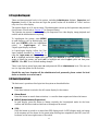
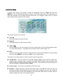
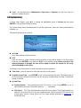
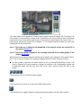
4. Main Screen And Basic Operations
The quad screen, as shown above, is the main screen after system startup. There are two types of
split window screens, including Full Screen and Quad. The system will remember the last one before
normal shutdown (as described in Section 5.6) of the system. In addition to the split windows, the
system time is displayed on the lower-left corner, the system states on the lower-right corner and the
rolling screen messages, shown while certain event occurs, on the lower corner.
The system states, from right to left, are described as the followings:
(1) Normal recording percentage,
(2) Alarm recording percentage,
(3) Mute state – speaker icon shown for not mute, not shown for mute,
(4) X2 state – X1, X2, or X4,
(5) Manual record ON/OFF – REC icon shown for ON,
(6) Backup state – Backup icon shown for backup,
(7) SEQ display ON/OFF or playback state – SEQ icon shown for SEQ display ON, other icons for
different playback states.
36%

16
4.1 Text Input
(with remote control)
There are certain circumstances that the system requires the user to enter text, such as system login,
camera title setup and so on. Please follow the steps below to enter text:
(1) Press ENTER to edit the highlighted option. The flashing cursor will be shown to indicate the
editing point. Besides, a keypad hint will be shown as below.
(2) Press ◄► to move the cursor to the left/right.
(3) Press
code
in text editing mode to change text case. (If this entry can accept number only,
pressing
code
will have no effects). Indicators on the screen show the current setting:
123 = Number only
abc = No capital letters
ABC = All capital letters
CODE = Internal code for the selected language, such as Chinese, Japanese, etc.
(4) Press a number key (1-9, 0) repeatedly until the character you want appears. (1 for 1 or space, 2
for 2, a/A, b/B, or c/C, for 5, j/J, k/K, l/L, MUTE for 6, m/M, n/N, o/O, the others as
shown on the keypad hint).
(5) Press mark to bring up a list of punctuation marks and special characters. The highlighted
character in the list shows the selected one. Press ▲▼◄► to change the selection.
(6) If you make a mistake, press BS to remove the character to the left of the cursor or press DEL to
delete the character at the current cursor position.
(7) In text editing mode, internal code box and mark list, press ENTER to exit and save changes,
press ESC to exit without making changes.
NOTE: if the mouse is used, clicking on the fields will display a virtual keyboard on which you can
type by clicking the letters.

17
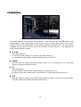
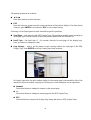
4.2 Login And Logout
There are three password levels in the system, including Administrator (highest), Supervisor and
Operator (lowest). If the user does not login the system, he/she will be treated as “Guest” and can
only view live video display.
The system allows up to 18 user accounts. The administrator can set up the login name and password
for each user. (Please refer to Section 6.7 for Password Setup.)
The Operator can operate live video display, the Supervisor live video display, image playback and
archive and the Administrator everything.
To login/logout the system, press MENU
in quad display to call up Menu display and
then press ENTER when the highlighted
option is Login/Logout to enter
Login/Logout display as shown.
In Login/Logout display, follow the Text
Input method described in Section 4.1 to
enter the Login name and Password, press
▲▼ to highlight and select Login option and then press ENTER to login the system. If the user
wants to logout the system, just press ▲▼ to highlight and select Logout option and then press
ENTER
. Press
ESC
to exit without making changes.
There is one factory-preset login name (aa) and password (11) at Administrator level. The user can
use it to login the system for the first time.
Should the user have forgotten all the administrator-level passwords, please contact the local
dealer or installer to recover from it.
4.3 Basic Operations
The basic user’s operations after login into the system are described below:
Numeric
Press these buttons to switch to the full-screen display for the camera.
Alarm Reset
Press this button to cancel alarm activation, i.e. reset the alarm outputs and silence the buzzer.
MODE (Administrator/Supervisor)
In quad display, press this button to change circularly the live/playback mode for the focus
window and the other windows that form a rectangle on the screen.
SEQ
Press this button to switch to or return from SEQ display mode. In SEQ display mode, each page
in the sequence will be shown for the preset page dwelling time sequentially and SEQ icon will
be shown on the lower-right corner of the screen.

18
SEARCH (Administrator/Supervisor)
In quad display, press this button to display the search menus. The system will remember the last
one the user chose.
REC
Press this button to force manual recording. To stop manual recording, press it again. All
cameras will be recorded as if the scheduled record is A/V and REC icon will be shown on the
lower-right corner of the screen if manual recording is ON.
MENU / ESC
In quad display, press this button to display the versatile menu.
Stop ( ) / PTZ
In quad display, press this button to enter PTZ control mode if the focus camera is a PTZ camera.
X2
In full screen display, press this button to enter Digital Zoom mode. Please refer to Section 4.4
Digital Zoom for the detailed operations in Digital Zoom mode.
▲▼◄►
Press these buttons to move focus. The title of the camera for the focus window is highlighted as
shown on the screen.
MUTE
Press this button to mute/not mute the audio.
+/-
Press these buttons to circulate up/down among the available quad displays.

19
4.4 Digital Zoom
The system supports X2/X4 Digital Zoom function. To use this function, press X2 button in full
screen display to enter Digital Zoom mode. There will be a zoom window shown in the video
window as shown. The zoom window (a) will always be shown at zoom factor X1, (b) can be shown
or hidden at zoom factor X2 and (c) will never be shown at zoom factor X4. The operations in
Digital Zoom mode are as below:
▲▼◄►
Press these buttons to
(a) move the zoom window if it’s shown in the video window, or
(b) navigate the video window around if the zoom factor is X2 or X4.
ENTER
Press this button to zoom in the zoom window, from X1 to X2 or from X2 to X4, if the zoom
window is shown in the video window.
X2
Press this button to
(a) show/hide the zoom window if the current zoom factor is X1/X2, or
(b) zoom out the video window back to zoom factor X1 if the current zoom factor is X4.
ESC
Press this button to escape from Digital Zoom mode and return to normal full screen display.
The video window will always return to zoom factor X1.

20
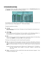
5. Menu Display
In quad display, press MENU to call up Menu display
as shown.
There are a variety of displays under Menu display.
In Menu display and all the subsequent displays, the
items enabled are shown in black-colored text and
those disabled in white-colored text. Please refer to
Section 4.2 for Login/Logout display.
The user’s operations are described as the followings:
▲▼
Press these buttons to change the highlighted
item.
ENTER
Press this button to enter the detailed display of the highlighted option. For the details of each
option, please refer to the following sections.
ESC
Press this button to escape from Menu display and return to quad display.
5.1 Status Display
In Menu display, press ▲▼ to change the highlighted option to Status and then press ENTER to
call up Status display as shown.
Status display includes Alarm Recording Status, Normal Recording Status, Camera Status, Alarm
Input Status, Product Serial Number and Product Version Number. Press ESC to escape from Status
display and return to Menu display.
Page is loading ...
Page is loading ...
Page is loading ...
Page is loading ...
Page is loading ...
Page is loading ...
Page is loading ...
Page is loading ...
Page is loading ...
Page is loading ...
Page is loading ...
Page is loading ...
Page is loading ...
Page is loading ...
Page is loading ...
Page is loading ...
Page is loading ...
Page is loading ...
Page is loading ...
Page is loading ...
Page is loading ...
Page is loading ...
Page is loading ...
Page is loading ...
Page is loading ...
Page is loading ...
Page is loading ...
Page is loading ...
Page is loading ...
Page is loading ...
Page is loading ...
Page is loading ...
Page is loading ...
Page is loading ...
Page is loading ...
Page is loading ...
Page is loading ...
Page is loading ...
Page is loading ...
Page is loading ...
Page is loading ...
Page is loading ...
Page is loading ...
Page is loading ...
Page is loading ...
Page is loading ...
Page is loading ...
Page is loading ...
Page is loading ...
Page is loading ...
Page is loading ...
Page is loading ...
-
 1
1
-
 2
2
-
 3
3
-
 4
4
-
 5
5
-
 6
6
-
 7
7
-
 8
8
-
 9
9
-
 10
10
-
 11
11
-
 12
12
-
 13
13
-
 14
14
-
 15
15
-
 16
16
-
 17
17
-
 18
18
-
 19
19
-
 20
20
-
 21
21
-
 22
22
-
 23
23
-
 24
24
-
 25
25
-
 26
26
-
 27
27
-
 28
28
-
 29
29
-
 30
30
-
 31
31
-
 32
32
-
 33
33
-
 34
34
-
 35
35
-
 36
36
-
 37
37
-
 38
38
-
 39
39
-
 40
40
-
 41
41
-
 42
42
-
 43
43
-
 44
44
-
 45
45
-
 46
46
-
 47
47
-
 48
48
-
 49
49
-
 50
50
-
 51
51
-
 52
52
-
 53
53
-
 54
54
-
 55
55
-
 56
56
-
 57
57
-
 58
58
-
 59
59
-
 60
60
-
 61
61
-
 62
62
-
 63
63
-
 64
64
-
 65
65
-
 66
66
-
 67
67
-
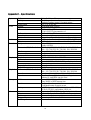 68
68
-
 69
69
-
 70
70
-
 71
71
-
 72
72


Comelit 49134 User manual
- Category
- Digital Video Recorders (DVR)
- Type
- User manual
Ask a question and I''ll find the answer in the document
Finding information in a document is now easier with AI
Related papers


Other documents
-
Svat CLEARVU11 User manual
-
-
ROHS H.264 Owner's manual
-
Viola Systems H.264 M8 User manual
-
Samsung SHR-6082P User manual
-
Channel Vision DVR-16N User manual
-
-
König SEC-DVR304-2 User manual
-
Samsung SRD-470D 500GB User manual
-
Eneo BCR-3016 Operating instructions