Kicker KX100.2 User manual
- Category
- DJ controllers
- Type
- User manual
This manual is also suitable for

KX100.2 & KX200.4 Technical Manual
Version 2.0
January 1, 2004
KX100.2 & KX200.4 Tech-
nical Manual

Features
KX100.2 & KX200.4 Technical Manual
Version 2.0
Page 2
Radically Advanced Chassis with removable shroud and improved heatsink technology. The heatsinks provide
the amplifier with longer runtime, improved reliability and performance. The height has been decreased for more
versatile installations. For those
Livin’ Loud
, the shrouds may be painted to match your car!
Low Impedance Operation The KX series amplifiers are stable down to 2 Ohm stereo and 4 Ohm mono. This
will allow the installer flexibility when designing the system. It will be easier to set up the right speaker impedance
for the amplifiers. One thing to remember:
800 watts at 4 ohms is equal to 800 watts at 2 ohms and is equal to 800
watts at 1 ohm. The point is, 800 watts is no greater than 800 watts no matter what impedance it is created at. 800
watts @ 2Ohms is NO greater than 800 watts at 4 Ohms!
SORT Protection Circuitry (Short circuit, Over-voltage, Reverse polarity, Thermal)
1. Short circuit- Protects the amplifier in case the speaker wire accidentally touches itself or the chassis of the car
or truck. This circuitry shuts down the amplifier before anything can cause damage requiring the need to be sent
in for repair.
2
.
.
Over-voltage- When the amplifier sees voltages above 16 volts or below 10.5 volts it will shut down to protect
the circuitry.
If the voltage regularly fluctuates to this degree, a qualified installer needs to check it out!
3. Reverse polarity- When the power and ground are hooked up in reverse, the amplifier will blow the fuse or
fuses on the side of the amplifier. Just check the wires and replace the fuses and you’re up and running without
damaging the amplifier.
4. Thermal- At 185ºF the amplifier will shut down in order for it to cool. At 175ºF the amplifier will resume normal
operation. When the amplifier shuts down due to thermal protection it is wise to let it cool down. If it does not
have enough time to cool down, it will go into thermal protection immediately when you turn it back up to the
volume level at which it shut off. If this consistently becomes a problem, check the impedance of the woofer and
make sure the amplifier is properly ventilated
MOSFET Power Supply Kicker amplifiers use MOSFET(Metal Oxide Semiconductor Field Effect Transistor) devices
in our power supplies in order to gain more efficiency. MOSFET devices create a lot less heat than standard Bipolar
transistor devices and switch at 30K which is well out of the audible region. With these factors taken into account,
it is easy to see why our amplifiers are
Livin’ Loud
.
KickBass These KX amplifiers come with a variable 12 dB bass boost at 40Hz so you can tweak the low end of your
system. If your system is lacking a little in the low end or your system has a dip around 40Hz, you can adjust the
control to give you more
KICK
without adding an equalizer.
Built-In Fixed Crossover These amplifiers have a built in 12 dB High pass or Low pass crossover. If you are using
the amp to run speakers that need crossover protection, flip the switch to HI PASS or if you are using the amplifier
to run subwoofers, flip the switch to LO PASS. Either way your amplifier will be able to handle all of your needs. The
crossover is defeatable for full range operation when there is no need for a crossover.
High & Low level inputs Whether you have a stock radio or an aftermarket stereo you will be able to hook up
the KX Series of amplifiers without the need for any adapters. High to low level adapters can rob your system of
important performance. We have eliminated the need for such adapters by building a series of amplifiers capable
of accepting a high or low level signal.

Custom tooled gold plated connectors Assure maximum power transfer and damping.
SAMS (Stereo And Mono Simultaneously) Amplifier will operate into a bridged mono load and a stereo load at the
same time. This type of system is great if the consumer is just starting out, or on a tight budget.
Three Year Warranty When you’re ‘Livin’ Loud’ you want the tunes to roll non-stop and we couldn’t agree
more. When you purchase your KX Amplifier from an authorized KICKER dealer we back it up with a full year war-
ranty...parts and labor. If you have an authorized KICKER dealer install it for you at the time of purchase we push
that warranty out to a full THREE years! We build our products to give you years of trouble free performance and
know that if it is installed right the first time you will get just that...so we back it up!
KX100.2 & KX200.4 Technical Manual
Version 2.0
Page 3
Features cont.
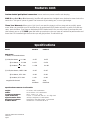
Model KX100.2 KX200.4
RMS Power
In Watts, All Channels Driven
@ 14.4V, 4W Stereo, <
1% THD 2 x 35 4 x 35
@ 2W Stereo, <
1% THD 2 x 50 4 x 50
@ 4W Mono, <
1% THD 1 x 100 2 x 100
@ 12.5V, 4W Stereo, 0.085% THD 2 x 25 4 x 25
@ 2W Stereo, 0.5% THD 2 x 40 4 x 40
@ 4W Mono, 0.5% THD 1 x 80 2 x 80
Length with Shroud 8.84” 11.84”
(22.45cm) (30.07cm)
Specifications common to all models:
Height: 2.5 inches / 6.35 centimeters
Width: 10.125 inches / 25.7 centimeters
Frequency Response: 20 Hz - 20 KHz, + 0, -1dB
Input Sensitivity: 170 mV - 5 V low level, 340 mV - 10 V high level
Signal-to-Noise Ratio: >95 dB, a-weighted, re: rated power
Electronic Crossover: Fixed high or low pass at 80Hz, 12 dB/octave
KickBass Boost: Variable 0 to +12 dB boost @ 40 Hz
Specifications

When selecting a location to mount your Kicker
amplifier be sure it is structurally sound and that
there are no items behind the area that could be
damaged by the screws. Check for wiring, brake
lines, fuel lines, gas tanks, etc.
All amplifiers generate heat under normal opera-
tion. Be sure to choose a location that allows ade-
quate ventilation for the amplifier. Also consider that
the air temperature inside an automobile’s trunk can
reach upwards of 140 degrees fahrenheit. An ampli-
fier mounted here may require additional cooling
needs such as fans or venting to allow cool opera-
tion. If possible, mounting the amp in the passenger
compartment will allow cooler operation.
Remember that the controls of the amp will need
to be accessible for adjustment later. Keep this in
mind as you choose your amplifier’s mounting loca-
tion.
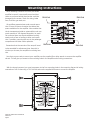
Now that you are ready to mount your amplifier, use the supplied 3mm allen wrench to remove the amplifier
shroud. This will give you access to the mounting holes in the amplifier and all wiring connections.
Mounting Instructions
Remove
Remove
Remove
Remove
With the shroud removed, you now have access to the four mounting holes in the mounting feet and all wiring
connections. Drill 4 holes using a 7/64” drill bit and use the supplied #8 screws to mount the amplifier.
KX100.2 & KX200.4 Technical Manual
Version 2.0
Page 4

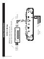
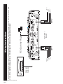
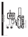
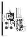
SOURCE UNIT
WARNING-Use Only One...
Never Both At The Same Time!!!
Speaker
Outputs
RCA
Outputs
LEFT +
LEFT -
RIGHT -
RIGHT +
High-Level
Inputs
KX100.2 & KX200.4 Technical Manual
Version 2.0
Page 5
KX100.2 Wiring
Wiring Instructions

SOURCE UNIT
WARNING-Use Only One...
Never Both At The Same Time!!!
Speaker
Outputs
RCA
Outputs
LEFT +
LEFT -
RIGHT -
RIGHT +
AMP 1 AMP 2
High-Level
Inputs
LEFT +
LEFT -
RIGHT -
RIGHT +
KX100.2 & KX200.4 Technical Manual
Version 2.0
Page 6
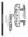
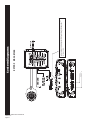
KX200.4 Wiring
Wiring Instructions
*See note on page 7 if
using High-Level inputs!

Wiring Instructions
SOURCE UNIT
Speaker
Outputs
RCA Dummy Plugs
LEFT +
LEFT +
LEFT -
RIGHT -
RIGHT +
AMP 1 AMP 2
High-Level
Inputs
LEFT -
RIGHT -
RIGHT +
When using both sets of High Level inputs, the supplied RCA dummy plugs must be inserted into the AMP 2 inputs in order for the fader to work
properly. If the amplifier is being used in any other configuration Do Not use the supplied dummy plugs!
KX100.2 & KX200.4 Technical Manual
Version 2.0
Page 7

Wiring cont.
The use of twisted pair interconnects is recommended for all installations to minimize noise. When routing these
cables through the automobile, try to keep them away from factory wiring harnesses and other power wiring. If
you need to cross any of this wiring do so at a 90 degree angle to reduce the possibility for noise problems.
When working with power connections it is always recommended that you disconnect the
battery to prevent accidents!
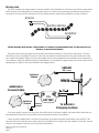
The ground should be connected to the amplifier first before making any of the other connections. This wire
should be as short as possible (24 inches or less) and connected to a paint/corrosion free solid metal area of the
car’s chassis.(See Diagram Below) Use the same gauge wire as recommended for the amplifiers power connection
to the battery. Adding an additional ground wire between the car battery’s negative post and the car chassis of this
same gauge (or larger) is also recommended. See diagram below.
GROUND
REMOTE
TURN-ON
BATTERY
FUSE
18"
or less
24" or less
12V
To Vehicle's
Charging System
Amplifier
Vehicle's
Chassis
Additional
Ground Cable
Vehicle's
Chassis
Factory
Ground
Source
Amplifier
Factory Wiring
If you ever need to remove the amp from the vehicle after it has been installed, the ground wire should be the
last wire disconnected from the amplifier, just the opposite as when you installed it.
A fuse must be installed within 18 inches of the battery to protect the power wire feeding your amplifier. This
fuse should be of at least the same value used in the amplifier but no higher than the capacity of the wire. See the
chart on next page for wire size and fusing recommendations.
KX100.2 & KX200.4 Technical Manual
Version 2.0
Page 8

Adjusting Amplifier Controls
On your Kicker amplifier there are rotary controls and switches on the end panel. These controls ensure the relia-
bility and performance of the amplifier, so they need to be set correctly. If you are using a KX150.4 you will have
two sets of rotary controls and switches. One set controls AMP1 and one set controls AMP2.
BEFORE TURNING ON THE S
YSTEM FOR THE FIRST TIME, MAKE SURE THAT
THE ROTARY CONTROLS ON THE SIDE OF THE AMPLIFIER ARE
TURNED FULLY COUNTER-CLOCKWISE!
CROSSOVER SWITCHES
NEVER CHANGE THE CROSSOVER SWITCH SETTING WITH THE SYSTEM ON!
The switches located on the end panel next to the RCA jacks are for setting the internal crossover. In the OFF
position the amplifier passes a full range signal to the speakers. Use the LO PASS position when connected to a
subwoofer. The HI PASS position should be selected when connected to any speakers which you do not want to
receive sub-bass information.
KX100.2 & KX200.4 Technical Manual
Version 2.0
Page 9
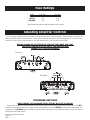
KX 200.4
KX 100.2
Model Fuse Size Wire Size
KX75.2 15A 8 GA
KX150.4 30A 8 GA
Specifications subject to change without prior notice.
Fuse Ratings

Crossover Control
Where you set the crossover is very subjective and can be fine tuned to match your listening preference or
speaker requirement. If the amplifier is driving small speakers (crossover set to HI PASS) this will eliminate the low
frequencies from damaging the high frequency speaker. If the amplifier is driving subwoofers (crossover set to LO
PASS). These are only guidelines because setting the right frequency depends on the listeners preferences. What
sounds good to one may not sound good to another. The following guidelines should give you a good understand-
ing for working with our amplifiers.
HI PASS
When using the amplifier to drive high and midrange speakers you will need to set the switch to
H
H
I
I
P
P
A
A
S
S
S
S
. This
activates the 12dB@80Hz high pass crossover and filters out low frequencies.
LO PASS
When using the amplifier to drive woofers the switch will need to be set to
L
L
O
O
P
P
A
A
S
S
S
S
.
.
This activates the 12 dB
@80Hz low pass crossover and filters out upper frequencies.
Bass Boost
The BASS BOOST control is designed to give you increased output at 40 Hz. The setting for this control is subjec-
tive, however, if you turn it up, you must go back and adjust the gain control to avoid clipping the amplifier.
Depending on the limits of the system or the limits of the woofers the BassBoost Control will give your system
that extra kick. It will provide up to 12 dB of boost @ 40 Hz, which will more than make your system
POUND!
GAIN CONTROLS
Remember, the gain control is not a volume control, it matches the output of the head unit to the input level of
the amplifier and must be adjusted properly for best performance. All the way up or down is not necessarily the
best. Turn the head unit up to about 3/4 volume. (eg. If the head unit goes to 30, turn it to 25.) Next, turn (clock-
wise) the gain on the amplifier up slowly until you can hear audible distortion, then turn it down just a little. Adjust
AMP 1 first, then proceed to AMP 2 if applicable. AMP 2 should be adjusted with the same process. If using the
amplifier to power subwoofers and the Bass Boost is adjusted, the gain must be re-adjusted to insure the amplifier
is not clipping.
KX100.2 & KX200.4 Technical Manual
Version 2.0
Page 10
Adjusting Amplifier Controls cont.

GROUND
REMOTE
TURN-ON
BATTERY
+12V
FUSE
RIGHT SPEAKER(S)
LEFT SPEAKER(S)
+
_
+
_
18"
or less
2 Ω
Min.
2Ω
Min.
SIGNAL IN
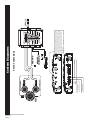
When the amplifier is driving speakers that do not require a crossover,
the crossover switch may be set to the OFF position. This will allow the
speakers to play full range.
OR...
If the amplifier is driving speakers that do require a crossover, set the
switch to HI PASS. This will allow only high frequencies to pass through
the amplifier to the speakers.
To Left Speaker
-
To Right Speaker
-
System Diagrams
KX100.2 Stereo Mode
KX100.2 & KX200.4 Technical Manual
Version 2.0
Page 11

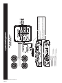
GROUND
REMOTE
TURN-ON
BATTERY
+12V
FUSE
18"
or less
+
_
MONO
SPEAKER
4 Ω
Min.
SIGNAL IN
If the amplifier is used to drive subwoofers, set the switch to LO PASS.
This will allow only low frequencies to pass through the amplifier
to the woofers.
To Woofer
-
KX100.2 Mono Mode
System Diagrams
KX100.2 & KX200.4 Technical Manual
Version 2.0
Page 12

GROUND
REMOTE
TURN-ON
BATTERY
+12V
FUSE
RIGHT SPEAKER(S)
LEFT SPEAKER(S)
+
_
+
_
18"
or less
+
_
MONO
SPEAKER
HIGH PASS
CROSSOVER
LOW
PASS
CROSS-
OVER
HIGH PASS
CROSSOVER
4 Ω
Min.
2 Ω
Min.
2Ω
Min.
SIGNAL IN
When the amplifier is driving speakers in the configuration above,
the crossover switch should be set to the OFF position. This will
allow the speakers to play full range. The speakers will need
passive crossovers in order to function properly. In the simpliest
form, the subwoofer will need a coil and the high and midrange
speakers will need a capacitor. These components will allow the
speakers to play in a dedicated frequency range for the best
sound quality.
To Woofer
To Left Speaker
-
-
To Right Speaker
-
KX100.2 SAMS Mode
System Diagrams
KX100.2 & KX200.4 Technical Manual
Version 2.0
Page 13

When AMP 1 or AMP 2 are driving speakers that do not require a crossover,
the crossover switch may be set to the OFF position. This will allow the
speakers to play full range.
OR...
If AMP 1 or AMP 2 are driving speakers that do require a crossover set the
switch to HI PASS. This will allow only high frequencies to pass through
the amplifier to the speakers.
SIGNAL IN AMP 1
SIGNAL IN AMP 2
+
-
+
-
+
-
+
-
GROUND
REMOTE
TURN-ON
BATTERY
+12V
FUSE
18"
or less
+
-
To Left Speaker
-
-
To Right Speaker
-
-
To Right Speaker
To Left Speaker
KX200.4 4 Channel
Stereo Mode
System Diagrams
KX100.2 & KX200.4 Technical Manual
Version 2.0
Page 14

+
-
GROUND
REMOTE
TURN-ON
BATTERY
+12V
FUSE
18"
or less
+
-
+
-
SIGNAL IN AMP 1
SIGNAL IN AMP 2
When AMP 1 is driving speakers that do not require a crossover,
the crossover switch may be set to the OFF position. This will allow the
speakers to play full range.
OR...
If AMP 1 is driving speakers that do require a crossover, set the switch
to HI PASS. This will allow only high frequencies to pass through the
amplifier to the speakers.
AND...
If AMP 2 is used to drive subwoofers, set the switch to LO PASS.
This will allow only low frequencies to pass through the amplifier
to the woofers.
To Woofer
To Left Speaker
-
-
To Right Speaker
-
System Diagrams
KX200.4 3 Channel
Stereo Mode
KX100.2 & KX200.4 Technical Manual
Version 2.0
Page 15

+
-
+
-
GROUND
REMOTE
TURN-ON
BATTERY
+12V
FUSE
18"
or less
If AMP 1 or AMP 2 are used to drive subwoofers, set the switch to LO PASS.
This will allow only low frequencies to pass through the amplifier
to the woofers.
MAKE SURE:
* The LEFT input must be split up and fed to the L & R Amp 1 inputs with
a Y-Adapter.
* The RIGHT input must be split up and fed to the L & R AMP 2 inputs with
a Y-Adapter.
SIGNAL IN AMP 1
SIGNAL IN AMP 2
To Right Speaker
To Left Speaker
-
-
KX200.4 2 Channel
Mono Mode
System Diagrams
KX100.2 & KX200.4 Technical Manual
Version 2.0
Page 16

Formulas
KX100.2 & KX200.4 Technical Manual
Version 2.0
Page 17
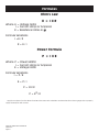
Ohm’s Law
E = I X R
Where: E = Voltage (Volts)
I = Current (Amps or Amperes)
R = Resistance (Ohms or
W
W
)
Formula Variations:
I =E / R
R = E / I
Power Formula
P = I X E
Where: P = Power (Watts)
I = Current (Amps or Amperes)
E = Voltage (Volts)
Formula Variations:
I = P / E
E = P / I
P = I
2
X R
P = E
2
/ R
Apply the numbers from the above formulas to the Power wire calculation to determine the minimum gauge wire to properly
supply the amplifier with current.

(Total RMS power output into 4
W
W
) x 2 = (Total input wattage [Watts])
(Total input wattage)
= (Maximum input current [Amps])
(Supply Voltage)
Example: Amplifier with a rating of 100 watts per channel into 4
W
W
200 x 2 = 400 Watts (Total input power)
400 Watts / 12.5 Volts = 32 amps (Total maximum draw)
Use this value of current draw to determine wire size
from the chart below.
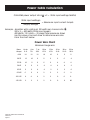
Power Wire Chart
Minimum Gauge wire
Draw Up to 4 to 7 to 10 to 13 to 16 to 19 to 22 to
(Amps) 4 ft. 7ft. 10ft. 13 ft. 16 ft. 19 ft. 22 ft. 28 ft.
0-20 14 12 12 10 10 8 8 8
20-35 12 10 8 8 6 6 6 4
35-50 10 8 8 6 6 4 4 4
50-65 8 8 6 4 4 4 4 2
65-85 6 6 4 4 2 2 2 0
85-105 6 6 4 2 2 2 2 0
105-125 4 4 4 2 2 0 0 0
125-150 2 2 2 2 0 0 0 00
Power Cable Calculation
KX100.2 & KX200.4 Technical Manual
Version 2.0
Page 18

• Damage due to improper installation.
• Subsequent damage to other components.
• Damage caused by exposure to moisture, excessive heat,
chemical cleaners, and/or UV radiation.
• Damage through negligence, misuse, accident or abuse.
Repeated returns for the same damage may be considered
abuse.
• Any cost or expense related to the removal or reinstallation
of product.
• Speakers damaged due to amplifier clipping or distortion.
• Items previously repaired or modified by any unauthorized
repair facility.
• Return shipping on non-defective items.
• Products with tampered or missing barcode labels.
• Products returned without a Return Authorization (RMA)
number.
• Freight Damage.
• The cost of shipping product to Kicker.
• Service performed by anyone other than Kicker.
KICKER drivers are capable of producing sound levels that can permanently
damage your hearing! Turning up a system to a level that has audible distortion is more damaging to
your ears than listening to an undistorted system at the same volume level. The threshold of pain is
always an indicator that the sound level is too loud and may permanently damage your hearing.
P
P
l
l
e
e
a
a
s
s
e
e
u
u
s
s
e
e
c
c
o
o
m
m
m
m
o
o
n
n
s
s
e
e
n
n
s
s
e
e
w
w
h
h
e
e
n
n
c
c
o
o
n
n
t
t
r
r
o
o
l
l
l
l
i
i
n
n
g
g
v
v
o
o
l
l
u
u
m
m
e
e
!
!
WARNING:
January 2004
ELETRONICS LIMITED WARRANTY
Kicker warrants this product to be free from defects in material and workmanship under normal use for a period of
T
T
H
H
R
R
E
E
E
E
(
(
3
3
)
)
M
M
O
O
N
N
T
T
H
H
S
S
from date of original purchase with receipt. When purchased from a Authorized KICKER Dealer it is warranted for
T
T
W
W
O
O
(
(
2
2
)
)
Y
Y
E
E
A
A
R
R
S
S
from date of original purchase with receipt. In all cases you
m
m
u
u
s
s
t
t
h
h
a
a
v
v
e
e
the
o
o
r
r
i
i
g
g
i
i
n
n
a
a
l
l
r
r
e
e
c
c
e
e
i
i
p
p
t
t
! Should service be neces-
sary under this warranty for any reason due to manufacturing defect or malfunction during the warranty period, Kicker will
repair or replace (at its discretion) the defective merchandise with equivalent merchandise at no charge. Warranty replacements
may have cosmetic scratches and blemishes. Discontinued products may be replaced with more current equivalent products.
This warranty is valid only for the
o
o
r
r
i
i
g
g
i
i
n
n
a
a
l
l
p
p
u
u
r
r
c
c
h
h
a
a
s
s
e
e
r
r
and is not extended to owners of the product subsequent to the original
purchaser. Any applicable implied warranties are limited in duration to a period of the express warranty as provided herein
beginning with the date of the original purchase at retail, and no warranties, whether express or implied, shall apply to this
product thereafter. Some states do not allow limitations on implied warranties, therefore these exclusions may not apply to you.
This warranty gives you specific legal rights; however you may have other rights that vary from state to state.
W
W
H
H
A
A
T
T
T
T
O
O
D
D
O
O
I
I
F
F
Y
Y
O
O
U
U
N
N
E
E
E
E
D
D
W
W
A
A
R
R
R
R
A
A
N
N
T
T
Y
Y
O
O
R
R
S
S
E
E
R
R
V
V
I
I
C
C
E
E
Defective merchandise should be returned to your local Authorized Stillwater Designs (Kicker) Dealer for warranty. Assistance in
locating an Authorized Dealer can be obtained by writing or calling Stillwater Designs direct. You can confirm that a dealer is
authorized by asking to see a current authorized dealer window decal.
If it becomes necessary for you to return defective merchandise directly to Stillwater Designs (Kicker), call the Kicker Customer
Service Department at (405)624-8510 for a Return Authorization (RMA) number. Package all defective items in the original con-
tainer or in a package that will prevent shipping damage, and return to
S
S
t
t
i
i
l
l
l
l
w
w
a
a
t
t
e
e
r
r
D
D
e
e
s
s
i
i
g
g
n
n
s
s
,
,
5
5
0
0
2
2
1
1
N
N
o
o
r
r
t
t
h
h
P
P
e
e
r
r
k
k
i
i
n
n
s
s
R
R
o
o
a
a
d
d
,
,
S
S
t
t
i
i
l
l
l
l
w
w
a
a
t
t
e
e
r
r
,
,
O
O
K
K
7
7
4
4
0
0
7
7
5
5
The RMA number must be clearly marked on the outside of the package. Return only defective components. Return of entire
cabinets, system packs, pairs, etc. increases your return freight charges. Non-defective items received will be returned freight
collect.
Include a dated
p
p
r
r
o
o
o
o
f
f
-
-
o
o
f
f
-
-
p
p
u
u
r
r
c
c
h
h
a
a
s
s
e
e
stating the Customer name, Dealer name, product purchased and date of purchase.
Warranty expiration on items without proof-of-purchase will be determined from type of sale and the manufacturing date
code. Freight must be prepaid; items received freight collect will be refused.
Failure to follow these steps may void your warranty. Any questions can be directed to the Kicker Customer Service
Department at (405)624-8510.
WHAT IS NOT COVERED ?
This warranty is valid only if the product is used for the purpose for which it was designed. It does not cover:
HOW LONG WILL IT TAKE ?
Kicker strives to maintain a goal of 72-hour service for all electronics (amps, crossovers, eq, etc.) returns. Delays may be
incurred if lack of replacement inventory or parts is encountered.
INTERNATIONAL WARRANTY
Contact your International Kicker dealer or distributor concerning specific procedures for your country’s warranty policies.
P.O. Box 459 • Stillwater, Oklahoma 74076 • U.S.A. • 405 624-8510

P.O. Box 459 – Stillwater, Oklahoma 74076 – U.S.A. – 405 624-8510
or www.Kicker.com
-
 1
1
-
 2
2
-
 3
3
-
 4
4
-
 5
5
-
 6
6
-
 7
7
-
 8
8
-
 9
9
-
 10
10
-
 11
11
-
 12
12
-
 13
13
-
 14
14
-
 15
15
-
 16
16
-
 17
17
-
 18
18
-
 19
19
-
 20
20


Kicker KX100.2 User manual
- Category
- DJ controllers
- Type
- User manual
- This manual is also suitable for
Ask a question and I''ll find the answer in the document
Finding information in a document is now easier with AI
Related papers
-
Kicker PXA300.4 Set-up and bridging Owner's manual
-
-
-
-
-
-
-
-
-