SCOTT PORTABLE GAS DETECTION INSTRUMENT User manual
- Category
- Smoke detectors
- Type
- User manual
This manual is also suitable for

1
MINI-SA PORTABLE
GAS DETECTION
INSTRUMENT

2
INTRINSICALLY SAFE GAS
LEVEL DETECTOR
SCOTT INSTRUMENTS
EXTON, PA 19341
R
USC
39NO
CERTIFIED BY UNDERWRITERS LABORATORIES INC.
ONLY AS TO INTRINSIC SAFETY
FOR USE IN HAZARDOUS LOCATIONS
CLASS I, DIV, 1, GROUPS A, B, C, & D.
CERTIFIED TO CANADIAN CSA STANDARD C22.2 NO. 157-92
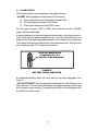
WARNING:
SUBSTITUTION OF COMPONENTS MAY IMPAIR INTRINSIC SAFETY.
USE ONLY WITH APPROVED BATTERIES.
TEMPERATURE CODE T3C.
CAUTION:
FOR SAFETY REASONS, THIS EQUIPMENT MUST BE
OPERATED AND SERVICED BY QUALIFIED PERSONNEL ONLY.
READ AND UNDERSTAND MANUAL BEFORE OPERATING AND SERVICING
CHANGE BATTERIES IN NON-HAZARDOUS AREA

3
SCOTT INSTRUMENTS
MINI-SA PORTABLE GAS
DETECTION INSTRUMENT
Contents
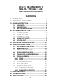
1.0 INTRODUCTION ................................................................. 4
2.0 OPERATIONAL ENVIRONMENT ........................................ 4
3.0 GENERAL INSTRUCTIONS ............................................... 5
3.1 UNPACKING .......................................................... 5
3.2 REGISTRATION ..................................................... 5
3.3 BATTERY INSTALLATION ..................................... 5
4.0 INSTRUMENT DESCRIPTION ............................................ 6
4.1 ALARM LEGENDS ................................................. 7
4.2 AUDIBLE ALARMS ................................................ 8
4.3 VIBRATION ALARM ............................................... 9
4.4 ALARM LED LIGHTS ............................................. 9
4.5 STATUS LIGHT ...................................................... 9
5.0 SWITCH FUNCTIONS AND DISPLAYS ........................... 10
6.0 OPERATING INSTRUCTIONS ........................................... 11
6.1 INSTRUMENT TURN ON / OFF ............................ 12
6.2 MENU SELECTION .............................................. 14
6.3 ZERO CALIBRATION MENU ................................ 17
6.4 SPAN CALIBRATION MENU ................................ 18
6.5 SENSOR REPLACEMENT MESSAGE ................. 22
6.6 PEAK / HOLD MENU ............................................ 23
6.6.1 PEAK ............................................................. 23
6.6.2 HOLD ............................................................. 25
6.7 ALARM SETPOINT MENU ................................... 26
6.8 TWA / STEL MENU .............................................. 29
6.9 CONFIGURATION MENU ..................................... 32
6.9.1 BATTERY SAVER MODE ............................... 32
6.9.2 PASSWORD PROTECTION .......................... 33
7.0 ERROR MESSAGES ........................................................ 37
8.0 CALIBRATION GASES .................................................... 38
9.0 SPECIFICATIONS ............................................................ 39

4
SCOTT INSTRUMENTS MINI-SA PORTABLE GAS DETECTOR
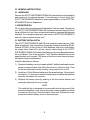
1.0 INTRODUCTION
The SCOTT INSTRUMENTS MINI-SA Portable Gas Detector is a self contained
instrument designed to detect and provide audible, visual, and tactile indication
of the presence of oxygen or toxic gas in the air. The toxic gas concentration is
monitored and shown in the graphic display in parts per million (ppm) of the
atmosphere. The oxygen concentration is shown in the graphic display as a
percent (%). When the gas level exceeds the preset level, alarms actuate
including a pulsing audible alarm tone, flashing LED, and a vibration alarm.
The alarm functions for toxic gases include a Time Weighted Average (TWA)
Alarm and a Short Term Exposure Level (STEL) Alarm.
Other features include AUTO CALIBRATION and self diagnostic capabili-
ties, a HOLD function that displays the lowest level detected, and user
adjustable high and low ALARM SETPOINTS. A battery life indicator con-
stantly monitors remaining battery capacity and a backlight provides visibil-
ity in low light situations.
Additional features include a PASSWORD PROTECT menu and a BAT-
TERY SAVER mode.
2.0 OPERATIONAL ENVIRONMENT
The SCOTT INSTRUMENTS MINI-SA Portable Gas Detector is designed to
be “INTRINSICALLY SAFE” suitable for operation in Class I, Division 1, Groups
A, B, C & D Hazardous Locations.

5
3.0 GENERAL INSTRUCTIONS
3.1 UNPACKING
Remove the SCOTT INSTRUMENTS MINI-SA instrument from its packaging
and examine it for external damage. If any damage is found, notify your
SCOTT INSTRUMENTS distributor, sales representative, or the SCOTT IN-
STRUMENTS Service Department.
3.2 REGISTRATION
Fill out and mail the postage paid Registration Card provided. Registering
your SCOTT INSTRUMENTS MINI-SA instrument assures that you will re-
ceive notification of any future enhancements and/or upgrades that become
available. You may also register your instrument on SCOTT INSTRUMENTS
web site “www.scottinstruments.com”.
3.3 BATTERY INSTALLATION
The SCOTT INSTRUMENTS MINI-SA instrument is powered by two “AAA”
Alkaline batteries. Use only alkaline (Eveready Energizer Industrial EN 92,
Duracell PC2400, or Ray-O-Vac AL-AAA) batteries. Use of any other batter-
ies except those listed will void the intrinsic safety listing of the SCOTT
INSTRUMENTS MINI-SA Portable Gas Detector. Use of rechargeable batter-
ies is prohibited. Two of the specified “AAA” Alkaline batteries will provide
approximately one hundred (100) hours of continuous non-alarming opera-
tion before requiring replacement.
Install the batteries as follows:
1) Remove the battery cover by loosening the #1-phillips-head captive cover
screw counterclockwise, then lifting the cover out of the housing. Then
lift the two batteries from the housing, using a small coin or tool.
2) Install two (2) AAA Alkaline batteries of the specified type. Note polarity
orientation (+/-) as shown inside the battery box and push the batteries
securely in between the contacts.
3) Replace the battery cover by pushing it into the bottom detents and
secure by tightening the cover screw.
NOTE
The metal belt clip is designed to be removed from the instrument. After
removing the battery cover, remove the cover screw completely and slide
the clip out of the cover. Store the clip for future use. Replace the cover
screw and reattach battery cover to the instrument.

6
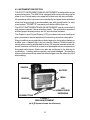
4.0 INSTRUMENT DESCRIPTION
THE SCOTT INSTRUMENTS MINI-SA INSTRUMENT is designed for use as
a personal monitor. The MINI-SA is equipped with a snap mounting clip for
ease of use. A break-away neck strap and rubber boot are also available.
All operations of the instrument are controlled by two push-button actuators
which are large enough to accommodate use with gloved hands. In each
menu screen, “PROMPTS” over each push-button define their use.
The SCOTT INSTRUMENTS MINI-SA INSTRUMENT case is constructed of
high impact resistant, flame retardant plastic. The push-button actuators
and the graphic display overlay are UV and chemical resistant.
The Graphic Liquid Crystal Display (LCD) provides continuous readings of
gas concentration as well as battery life remaining and other information.
Alarm conditions are signaled by an alarm legend on the graphic display, an
audible tone, a flashing light, and an internal vibration. Audible tones for
certain alarms can be suspended for thirty (30) second intervals while oth-
ers will continue until the unit is reset in an atmosphere that corresponds to
the preset safe values. Alarms can also be configured to be latching or
nonlatching. Latching alarms operate until acknowledged. Nonlatching
alarms clear automatically when the detected gas is on the safe side of the
alarm setting.
MINI-SA INSTRUMENT
(w/ H
2
S Sensor shown for reference)
FIGURE 1
PUSHBUTTONS
LED
(GREEN OR RED
DEPENDING
SENSOR
GRAPHIC
BATTERY
MENU

7
4.1 ALARM LEGENDS
The following alarm legends appear in the graphic display:
“ALARM” flashing legend indicates one of the following:
a) Gas concentration which exceeds the preset level
b) A Time Weighted Average (TWA) Alarm
c) A Short Term Exposure Level (STEL) Alarm.
For toxic gas, the ppm, TWA, or STEL level detected and the “ALARM”
legend will flash alternately.
A graphic battery level indicator appears continuously on the display screen.
The indicator shows battery capacity as ten (10) lines inside a picture of a
battery. Each line represents approximately 10% of battery time remaining.
The battery level indicator flashes when the batteries are low. This will occur
when approximately 10% of battery life remains.
EACH LINE REPRESENTS
APPROXIMATELY 10%
OF BATTERY TIME REMAINING
FIGURE 2
BATTERY LEVEL INDICATOR
An exhausted battery alarm will occur after the last bar disappears. See
Figure 2.
“HOLD ACTIVATED” flashing legend indicates that the HOLD feature has
been selected. The instrument will display the highest reading of a toxic gas
or the lowest oxygen reading. This reading will continue to be displayed until
the HOLD function is reset.

8
4.2 AUDIBLE ALARMS
The SCOTT INSTRUMENTS MINI-SA has an audible alarm which is acti-
vated when any of the following conditions occurs:
- The preset gas alarm level is exceeded (ALARM)
- The Time Weighted Average (TWA) is exceeded
- The Short Term Exposure Limit (STEL) is exceeded
- The battery is exhausted
- The sensor is missing or incompatible
In addition, each time the instrument is turned ON, the audible alarm will
pulse three times.
The following describes the function of the Audible Alarm during the alarm
conditions listed above:
GAS ALARM – The Audible Alarm sounds when a gas concentration is de-
tected that exceeds the chosen alarm level, or when a TWA or STEL alarm
value is exceeded. A repetitive pulsing tone will occur at one (1) second
intervals while the alarm condition exists.
In the LATCHING alarm mode, selected in the Alarm Setpoint Menu, after an
alarm condition has cleared, the alarm indication will continue until the alarm
is acknowledged by depressing a pushbutton. In the NON-LATCHING alarm
mode, all alarm indications clear when the alarm condition clears. In either
mode, the instrument gives an “all clear” signal with three audible beeps,
three flashes of the Red Alarm Light, and three vibration pulses when the
alarm indication is cleared.
When an Audible Alarm sounds, depressing either pushbutton on the instru-
ment will silence the Audible Alarm for thirty (30) seconds. If the original
alarm condition still exists after the thirty (30) second silence period, the
Audible Alarm will sound again. The Audible Alarm can be silenced repeat-
edly by depressing a pushbutton.
LOW BATTERY – An Audible Alarm tone will pulse once every fifteen (15)
seconds to indicate when less than 10% of battery life remains.
MISSING SENSOR – The Audible Alarm for a missing or incompatible sen-
sor is identical to the pulsing one (1) second tone that occurs during an
ALARM condition. Depressing a pushbutton to acknowledge the condition
turns the unit OFF.

9
4.3 VIBRATION ALARM
An internal vibrating motor activates whenever the Audible Alarm sounds. The
Vibration Alarm operates as a secondary alarm feature in high noise environ-
ments where the audible alarm may be difficult to hear.
The Vibration Alarm is reset the same as the Audible Alarm as described in
Section 4.2.
The Vibration Alarm will also pulse briefly whenever the MINI-SA instrument
is turned ON or OFF.
WARNING
THE VIBRATION ALARM DOES NOT FUNCTION FOR THE LOW BAT-
TERY INDICATION.
4.4 ALARM LIGHT
The SCOTT INSTRUMENTS MINI-SA instrument contains a Red Light Alarm
LED (Light Emitting Diode) which flashes whenever any Alarm Condition oc-
curs. It will continue to flash when the Audible Alarm is silenced and will flash
as long as the alarm condition is present. In the LATCHING alarm mode,
selected in the Alarm Setpoint Menu, after an alarm condition has cleared,
the alarm indication will continue until the alarm is acknowledged by de-
pressing a pushbutton. In the NON-LATCHING alarm mode, all alarm indica-
tions clear when the alarm condition clears. In either mode, the instrument
gives an “all clear” signal with three audible beeps, three flashes of the Red
Alarm Light, and three vibration pulses when the alarm indication is cleared.
4.5 STATUS LIGHT
The instrument also has a Green Status LED that flashes periodically, indi-
cating continuing instrument operation.

10
5.0 SWITCH FUNCTIONS AND DISPLAYS
All operations on the MINI-SA Portable Detector are controlled by two push-
buttons located on the bottom of the unit. The operations vary depending on
the operating mode and the graphic display appearing above the two switches.
The unit sounds a brief audible “beep” whenever either pushbutton is de-
pressed while the instrument is on. Whenever the instrument is turned ON or
OFF, three successive audible tones will sound and the Red Alarm LED will
flash. The Green Status LED will flash once every fifteen (15) seconds during
instrument operation. When in the BATTERY SAVER mode, the Green Sta-
tus LED flash rate increases to once every five (5) seconds.
When the unit is in the operating mode, depressing the Display Backlight
Pushbutton will illuminate the graphic display for fifteen (15) seconds. A light
bulb icon for the Backlight is located above the pushbutton on the operat-
ing mode screen. Depressing the button again extinguishes the Backlight.
The Backlight is sustained ON or OFF while the MENU operations are in
progress, except for calibration. In an alarm condition, the Backlight flashes
for the duration of the alarm indication.
When in the BATTERY SAVER mode, the instrument graphic display will be
blank. Depressing either pushbutton will turn on the graphic display. The
display remains on for thirty (30) seconds after the last pushbutton opera-
tion.
WARNING
USE OF THE DISPLAY BACKLIGHT FOR EXTENDED PERIODS OF TIME
WILL REDUCE BATTERY SERVICE LIFE.
COMPONENT LOCATIONS
FIGURE 3
PUSHBUTTONS (2)
LED
(GREEN OR RED
DEPENDING
SENSOR
GRAPHIC

11
6.0 OPERATING INSTRUCTIONS
Before using this instrument, read and understand ALL instructions for ALL
operating modes described in this Section. Prior to use, the instrument should
be checked for proper calibration as described in this Section.
WARNING
BEFORE EACH DAY’S USAGE, THE SENSITIVITY OF THE GAS SENSOR
MUST BE TESTED ON A KNOWN CONCENTRATION OF CALIBRATION
GAS.
WARNING
ACTUAL CALIBRATION SHOULD ONLY BE PERFORMED BY QUALI-
FIED INSTRUMENT MAINTENANCE PERSONNEL.
WARNING
ANY INDICATION OR READING DENOTING A TOXIC GAS OR A LACK
OF OXYGEN SIGNIFIES THE NECESSITY TO FOLLOW ESTAB-
LISHED COMPANY PROCEDURES FOR THE INDICATED CONCEN-
TRATIONS OF THE PARTICULAR GAS.
WARNING
USE IN OXYGEN ENRICHED ATMOSPHERES (ABOVE 25% O
2
) MAY BE
HAZARDOUS.
WARNING
CONFIRM THE INSTRUMENT’S BASIC CALIBRATION IS APPRO-
PRIATE FOR THE INTENDED USE.

12
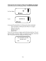
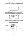
6.1 INSTRUMENT TURN ON / OFF
To turn the instrument ON, depress either pushbutton. Three successive “beeps”
will sound. The Red LED will flash and the vibration alarm will pulse for each
“beep.” The graphic display will show one of the following screens while the
instrument initializes. The sensor installed in the unit defines which display is
shown:
SCOTT INSTRUMENTS
For Toxic Gases MINI-SA VERSION X.X
<gas> SENSOR
INITIALIZING
All toxic gas screens appear similar, therefore wherever the symbol <gas>
appears on any of the graphic display screens in this manual, it will be substi-
tuted with the applicable toxic sensor (either CO, Cl
2
, ClO
2,
HCN, H
2
S, NH
3
,
NO
2
, NH
3,
PH
3
or SO
2
) installed in the instrument at the time. For some toxic
gases, the screen display will show 0.0 or 0.00 resolution.
The following toxic gas sensors are available in the MINI-SA:
CO = Carbon Monoxide
Cl
2
= Chlorine
ClO
2
= Chlorine Dioxide
HCN = Hydrogen Cyanide
H
2
S = Hydrogen Sulfide
NH
3
= Ammonia
NO
2
= Nitrogen Dioxide
PH
3
= Phosphine
SO
2
= Sulphur Dioxide
Refer to Section 9.0 for sensor specifications.
SCOTT INSTRUMENTS
For O
2
MINI-SA VERSION X.X
O
2
SENSOR
INITIALIZING
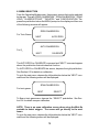
After a few seconds, the instrument will sound a single “beep” and go to the Operat-
ing Mode where the graphic display will show one of the following screens:
Note: If a new sensor is installed or if batteries have been removed for more
than a few minutes, the initialization sequence may take longer. If the

13
sensor type has been changed or if the previous calibration was not suc-
cessful, the bottom line of the display will show “CALIBRATION REQUIRED”.
For Toxic Gases 0
MENU
For O
2
20.9% O
2
MENU
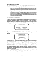
In the normal Operating Mode, the following information is displayed:
- Gas concentration in either ppm (toxic Gas) or % (oxygen)
- Battery life indication
- Backlight prompt
- Menu prompt
To turn OFF the instrument, depress and hold both push-buttons. The unit
will sound three successive “beeps” accompanied by flashes of the Red
LED. The instrument will then display the following screen:
DO YOU WANT TO TURN
THE UNIT OFF?
YES NO
ppm
<gas>

14
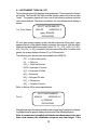
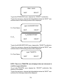
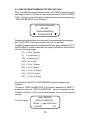
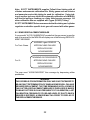
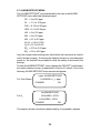
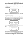
6.2 MENU SELECTION
From the Operating Mode screen, there are six menus that can be selected
by the user. They are “ZERO CALIBRATION,” “SPAN CALIBRATION,” “PEAK/
HOLD,” “ALARM SETPOINT,” “TWA/STEL,” and “CONFIGURATION.” De-
press the pushbutton below the MENU prompt on the display and then one
of the following screens will appear:
ZERO CALIBRATION
For Toxic Gases
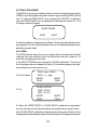
NEXT AUTO ZERO
AUTO CALIBRATION
For O
2
NEXT CALIBRATE
The AUTO ZERO or CALIBRATE command and “NEXT” command appear
above the pushbutton that activates that function.
To AUTO ZERO or CALIBRATE the sensor, depress the right pushbutton.
See Section 6.3 for details on calibration.
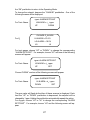
To go to the next menu, depress the left pushbutton below the “NEXT” com-
mand and the following screen will be displayed:
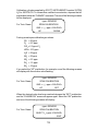
SPAN CALIBRATION
For toxic gases
NEXT SELECT
To Span a toxic gas sensor, depress the “SELECT” pushbutton. See Sec-
tion 6.4 for details on span calibration.
NOTE: There is no span calibration screen when using the Mini-Sa
portable to detect oxygen. The screen will go directly to the next
menu.
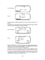
To go to the next menu, depress the left pushbutton below the “NEXT” com-
mand and the following screen will be displayed:

15
PEAK / HOLD
NEXT SELECT
To go to the PEAK/HOLD menu, depress the “SELECT” pushbutton.
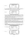
To go to the next menu, depress the left pushbutton below the “NEXT” com-
mand and one of the following screens will be displayed:
<gas> ALARM SETPOINT
For Toxic Gases
NEXT SELECT
O
2
ALARM SETPOINT
For O
2
NEXT SELECT
To go to the ALARM SETPOINT menu, depress the “SELECT” pushbutton.
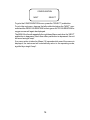
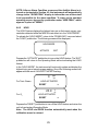
To go to the next menu, depress the left pushbutton below the “NEXT” com-
mand and one of the following screens will be displayed:
<gas> TWA/STEL
For Toxic Gases
NEXT SELECT
NOTE: There is no TWA/STEL menu displayed when an instrument is
used for oxygen detection.
To go to the TWA/STEL menu, depress the “SELECT” pushbutton. See
Section 6.8 for details.
To go to the next menu, depress the left pushbutton below the “NEXT” com-
mand and the following screen will be displayed:

16
CONFIGURATION
NEXT SELECT
To go to the CONFIGURATION menu, press the “SELECT” pushbutton.
To go to the next menu, depress the left pushbutton below the “NEXT” com-
mand and the ZERO CALIBRATION for toxic gas or AUTO CALIBRATION for
oxygen screen will again be displayed.
The MINI-SA will scroll repeatedly through these Menus each time the “NEXT”
pushbutton is depressed. Each time either pushbutton is depressed, the unit
will sound a single “beep”.
If no menu action is taken for fifteen (15) seconds while one of the menus is
displayed, the instrument will automatically return to the operating mode,
signified by a single “beep”.

17
6.3 ZERO CALIBRATION MENU
The MINI-SA instrument can be Auto Zeroed at any time. An Auto Zero should
only be performed in an area known to be free of toxic gas or any known
cross sensitive materials. See Section 8.0 for SCOTT INSTRUMENTS sup-
plied calibration gas cylinders. When performing an auto-zero with an oxy-
gen unit, be sure the area contains 20.9% oxygen.
To perform Zero Calibration of the sensor as described in Section 6.2, de-
press the “AUTO ZERO” pushbutton when the ZERO CALIBRATION menu
screen is displayed.
The instrument will display one of the following screens while it calibrates the
appropriate sensor.
<gas> SENSOR
For Toxic Gases ZERO CALIBRATION
2
O
2
SENSOR
For O
2
ZERO CALIBRATION
2
The instrument display will count down 2 seconds while the sensor is ze-
roed. After a successful “ZERO CALIBRATION”, the instrument will sound a
“beep” and automatically go back into the Operating Mode.
If, during the “ZERO CALIBRATION”, the unit detects that the sensor is out of
range, an error message will be displayed. See Section 7.0 for a description
of error messages.

18
6.4 SPAN CALIBRATION MENU FOR TOXIC GAS ONLY
Note: The MINI-SA software requires that an “AUTO ZERO” be performed as
described in Section 6.3 before the instrument will allow a “SPAN CALIBRA-
TION”. Failure to do so will display the following screen when attempting a
“SPAN CALIBRATION” of the instrument:
AUTO ZERO REQUIRED
BEFORE
SPAN CALIBRATION
ACKNOWLEDGE
Depress both pushbuttons simultaneously to acknowledge this message
and “AUTO ZERO” the instrument per Section 6.3 to procede.
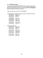
The MINI-SA instrument can be calibrated with span gas supplied by SCOTT
INSTRUMENTS or with a calibration gas supply certified to a concentration
within the following ranges:
CO = 25 to 120 ppm
Cl
2
= 5 ppm only Cl
2
ClO
2
= 5 ppm only Cl
2
HCN = 2.0 to 25.0
H
2
S = 10 to 110 ppm
NH
3
= 10 to 40 ppm
NO
2
= 2.0 to 15.0 ppm
PH
3
= 0.5 to 4.5 ppm
SO
2
= 2.0 to 18.0 ppm
See Section 8.0 for SCOTT INSTRUMENTS supplied calibration gas
cylinders.
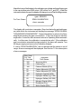
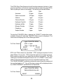
To perform “SPAN CALIBRATION” of the sensor, depress the “SELECT”
pushbutton when the “SPAN CALIBRATION” screen is displayed as de-
scribed in Section 6.2. The instrument will display the one of the following
screens:
<gas> SENSOR
For Toxic Gases SPAN CALIBRATION
USING <_> ppm <CALGAS>
CHANGE OK

19
Calibration cylinders supplied by SCOTT INSTRUMENTS contain 25 PPM
H
2
S or 50 PPM CO. To use another certified concentration, depress the left
pushbutton below the “CHANGE” command. The one of the following screens
will be displayed:
<gas> SENSOR
For Toxic Gases SPAN CALIBRATION
GAS = <_> ppm <CALGAS>
UP DOWN
Factory preset span calibration gas values:
CO = 50 ppm
Cl
2
= 5.0 ppm
ClO
2
= 5.0 ppm Cl
2
HCN = 10.0 ppm
H
2
S = 25 ppm
NH
3
= 25 ppm
NO
2
= 5.0 ppm
PH
3
= 1.0 ppm
SO
2
= 10 ppm
If you select the “UP” pushbutton, for example, one of the following screens
will display with the number value flashing:
<gas> SENSOR
For Toxic Gases SPAN CALIBRATION
GAS = <_> ppm <CALGAS>
UP SET
When the desired value has been reached depress the “SET” pushbutton
and the “CHANGE/OK” screen will appear again. Select the “OK” pushbutton
and one of the following screens will display:
<gas> SENSOR
For Toxic Gases SPAN CALIBRATION
INJECT <_> ppm <CALGAS>
EXIT

20
This screen will remain on until the instrument detects calibration gas. If no
calibration gas is detected after thirty (30) seconds, the instrument will sound
a single beep and return to the operating mode.
Depressing the “EXIT” pushbutton will also return the instrument to normal
operation with no calibration having occurred. The last successful calibration
will remain valid.
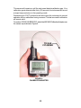
To continue “SPAN CALIBRATION”, attach the 40014936 Calibration Adapter over
the sensor cap as shown in Figure 4.
FIGURE 4
CALIBRATION ADAPTER
TO GAS
CYLINDER
Page is loading ...
Page is loading ...
Page is loading ...
Page is loading ...
Page is loading ...
Page is loading ...
Page is loading ...
Page is loading ...
Page is loading ...
Page is loading ...
Page is loading ...
Page is loading ...
Page is loading ...
Page is loading ...
Page is loading ...
Page is loading ...
Page is loading ...
Page is loading ...
Page is loading ...
Page is loading ...
Page is loading ...
Page is loading ...
Page is loading ...
Page is loading ...
Page is loading ...
Page is loading ...
Page is loading ...
Page is loading ...
Page is loading ...
Page is loading ...
-
 1
1
-
 2
2
-
 3
3
-
 4
4
-
 5
5
-
 6
6
-
 7
7
-
 8
8
-
 9
9
-
 10
10
-
 11
11
-
 12
12
-
 13
13
-
 14
14
-
 15
15
-
 16
16
-
 17
17
-
 18
18
-
 19
19
-
 20
20
-
 21
21
-
 22
22
-
 23
23
-
 24
24
-
 25
25
-
 26
26
-
 27
27
-
 28
28
-
 29
29
-
 30
30
-
 31
31
-
 32
32
-
 33
33
-
 34
34
-
 35
35
-
 36
36
-
 37
37
-
 38
38
-
 39
39
-
 40
40
-
 41
41
-
 42
42
-
 43
43
-
 44
44
-
 45
45
-
 46
46
-
 47
47
-
 48
48
-
 49
49
-
 50
50


SCOTT PORTABLE GAS DETECTION INSTRUMENT User manual
- Category
- Smoke detectors
- Type
- User manual
- This manual is also suitable for
Ask a question and I''ll find the answer in the document
Finding information in a document is now easier with AI
Other documents
-
BW Technologies GasAlert Extreme NH3 User manual
-
-
Altair ALTAIR 5X Owner's manual
-
 PHD Products PHD Carbon Monoxide Alarm 13-027 User manual
-
Honeywell PHD6 Quick Reference Manual
-
-
RKI Instruments GX-2001 Reference guide
-
-
-
Black & Decker MULTI-GAS DETECTORS User manual
