
IMPORTANT MANUAL -- Do not throw away
MANUAL IMPORTANTE -- No lo descarte
MANUEL IMPORTANT -- À Conserver
WARNING:
Read and follow all Safety Rules and Operating Instructions before
using this product. Failure to do so can result in serious injury .
ADVERTENCIA:
Lea el manual de instrucciones y siga todas las advertencias e
instrucciones de seguridad. El no hacerlo puede resultar en lesiones
graves.
AVERTISSEMENT:
Veuillez lire le manuel d’instructions et bien respecter tous les
avertissements et toutes les instructions de sécurité. Tout défaut
de le faire pourrait entraîner des blessures graves.
Instruction Manual
Manual de Instrucciones
Manuel d’Instructions
McCulloch
9335 Harris Corners
Charlotte, NC 28269
ENGLISH
ESPAÑOL
FRANÇAIS
McCulloch
850 Matheson Blvd. West
Mississauga, Ontario L5V 0B4
115376927 Rev. 2 5/15/10 BRW
Please do not return product to retailer.
Por favor, no devuelva el producto al lugar de compra.
Veuillez ne pas retourner le produit au détaillant.
1--800--554--6723
www.mccullochpower.com
Register your product online at:
Registre su producto en línea en:
Enregistrez votre produit en ligne à l’adresse :

-- 2 --
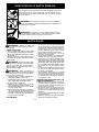
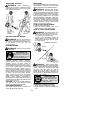
IDENTIFICATION OF SAFETY SYMBOLS
WARNING: This unit can be dangerous! Careless or improper
use can cause serious injury.
The blower can throw objects vio-
lently. You can be blinded or injured.
Always wear hearing protection and
safety glasses marked Z87. Always
wear heavy, long pants, long
sleeves, boots and gloves.
Always stop unit and disconnect spark plug before
cleaning or servicing.
Secure hair above shoulder length. Do
not wear jewelry , loose clothing, or
clothing with loosing hanging straps,
ties, tassels, etc. They can be caught in
moving parts.
Hazard zone for thrown objects. Keep children, by-
standers, and animals away from work area a mini-
mum of 30 feet (10 meters) when starting or operating
unit. Do not point blower nozzle in the direction of
people or pets.
WARNING: Stop the engine before opening the vacuum inlet door . The engine must
be stopped and the impeller blades no longer turning to avoid serious injury from the rotating
blades. Gently tilt the handle of the screwdriver toward the front of the unit to release the latch
while pulling up on the vacuum inlet cover with your other hand.
WARNING: Read the operator’s manual before use. Failure to
follow instructions could result in serious injury to the operator and/or
bystanders. Save operator’s manual.
WARNING: While vacuuming or blowing
debris, hold the unit with the muffler side facing
away from your body and clothes.

-- 3 --
IDENTIFICATION OF SAFETY SYMBOLS
WARNING: Fire hazard. Never mix, pour, or store gasoline or
use the unit near a flame or sparks (including smoking, open flames, or
work that can cause sparks).
When using the vacuum attachment, the unit is designed to pick up dry
material such as leaves, grass, small twigs, and bits of paper. Do not
vacuum stones, gravel, metal, broken glass, etc., to avoid severe dam-
age to the impeller.
WARNING: The muffler is very hot during and after use. Do
not touch the muffler, muffler guard, or surrounding surfaces, or allow
combustible material such as dry grass or fuel to do so.
SAFETY RULES
WARNING: Failure to follow all
Safety Rules and Precautions can result in
serious injury.
KNOW YOUR UNIT
S Read your instruction manual carefully until
you completely understand and can follow
all warnings and safety rules before operat-
ing the unit.
D Restrict unit to users who understand and
will follow all warnings and safety rules in
this manual.
WARNING: Inspect area before start-
ing unit. Remove all debris and hard objects
such as rocks, gl a ss, wire , etc. tha t can rico-
chet, be thrown, or otherwise cause injury or
damage during operation.
WARNING: While vacuuming or
blowing debris, hold the unit with the muffler
side facing away from your body and clothes.
Use your unit as a blower for:
D Sweeping debris or grass clippings from
driveways, sidewalks, patios, etc.
D Blowing grass clippings, straw, or leaves into
piles, around joints, or between bricks.
Use your unit as a vacuum for:
D Picki n g up dry ma te r i a l such as leaves,
grass, small twigs, and bits of paper.
D For best results during vacuum use, operate
your unit at high speed.
D Move slowly back and forth over the mate-
rial as you vacuum. Avoid forcing the unit
into a pile of debris as this can clog the unit.
D Keep the vacuum tube about an inch above
the ground for best results.
PLAN AHEAD
D Always wear eye protection when operat-
ing, servicing, or performing maintenance
on unit. W earing eye protection will help to
prevent rocks or debris from being blown or
ricocheting into eyes and face which can
result in blindness and/or serious injury.
Eye protection should be marked Z87.
D Always wear foot protection. Do not go
barefoot or wear sandals.
D Always wear respirator or face mask when
working with unit in dusty environments.
D Secure hair so it is above shoulder length.
Keep loose hair, loose clothing, fingers, and
all other parts of the body away from openings
and moving parts. Hair, jewelry , loose cloth-
ing, or clothing with loosely hanging straps,
ties, tassels, etc., can be caught in moving
parts.
D Do not operate unit when you are tired, ill, up-
set, or if you are under the influence of alco-
hol, drugs, or medication.
D Keep children, bystanders, and animals
away from work area a minimum of 30 feet
(10 meters) when starting or operating unit.
Do not point the blower nozzle in the direc-
tion of people or pets.
HANDLE FUEL WITH CAUTION, IT IS
HIGHLY FLAMMABLE
D Eliminate all sources of sparks or flame (in-
cluding smoking, open flames, or work that
can cause sparks) in the areas where fuel is
mixed, poured, or stored.
D Mix and pour fuel in an outdoor area; store
fuel in a cool, dry, well ventilated place; use
an approved, marked container for all fuel
purposes.
D Do not smoke while handling fuel or while
operating the unit.
D Make sure the unit is properly assembled
and in good operating condition.

-- 4 --
D Do not fill fuel tank while engine is hot or
running.
D Avoid spilling fuel or oil. Wipe up fuel spills
before starting engine.
D Move at least 10 feet (3 meters) away from
fuel and fueling site before starting engine.
D Always store gasoline in a container ap-
proved for flammable liquids.
OPERATE YOUR UNIT SAFELY
WARNING: Stop the engine before
opening the vacuum inlet door. The engine
must be stopped and the impeller blades no
longer turning to avoid serious injury from the
rotating blades.
WARNING: While vacuuming or
blowing debris, hold the unit with the muffler
side facing away from your body and clothes.
D Inspect unit before each use for worn,
loose, missing, or damaged parts. Do not
use until unit is in proper working order.
D Keep outside surfaces free of oil and fuel.
D Never start or run engine inside a closed
room, building or other unventilated area.
Breathing exhaust fumes can kill.
D To avoid static electricity discharge, do not
wear rubber gloves or any other insulated
gloves while operating unit.
D Do not set unit on any surface except a
clean, hard area while engine is running.
Debris such as gravel, sand, dust, grass,
etc. could be picked up by the air intake and
thrown out through discharge opening,
damaging unit, property , or causing serious
injury to bystanders or operator.
D Avoid dangerous environments. Do not use
in unventilated areas or where explosive
vapors or carbon monoxide build up could
be present.
D Do not overreach or use from unstable sur-
faces such as ladders, trees, steep slopes,
rooftops, etc. Keep firm footing and balance
at all times.
D Never place objects inside the blower
tubes; always direct t he b lowing debris away
from people, animals, glass, and solid objects
such as trees, automobiles, walls, etc. The
force of air can cause rocks, dirt, or sticks to
be thrown or to ricochet which can hurt people
or animals, break glass, or cause other dam-
age.
D Never run unit without the proper equipment
attached. When using your unit as a blower,
always install blower tubes. When using your
unit as a vacuum, always install vacuum
tubes and vacuum bag assembly. Make sure
vacuum bag assembly is completely zipped.
D Check air intake opening, blower tubes,
vacuum tubes, and elbow tube frequently ,
always with engine stopped and spark plug
disconnected. Keep vents and discharge
tubes free of debris which can accumulate
and restrict proper air flow.
D Never place any object in the air intake open-
ing as this could restrict proper air flow and
cause damage to the unit.
D Never use for spreading chemicals, fertiliz-
ers, or other substances which may contain
toxic materials.
D To avoid spreading fire, do not use near leaf
or brush fires, fireplaces, barbecue pits,
ashtrays, etc.
D Use only for jobs explained in this manual.
MAINTAIN YOUR UNIT PROPERLY
WARNING: Disconnect spark plug be-
fore performing maintenance except for carbu-
retor adjustmen ts.
D Have all maintenance other than the rec-
ommended procedures described in the in-
struction manual performed by an autho-
rized service dealer.
D Use only recommended McCulloch re-
placement parts; use of any other parts
may void your warranty and cause damage
to your unit.
D Empty fuel tank before storing the unit. Use
up fuel left in carburetor by starting engine and
letting it run until it stops.
D Do not use any accessory or attachment
other than those recommended by manufac-
turer for use with your unit.
D Do not store the unit or fuel in a closed area
where fuel vapors can reach sparks or an
open flame from hot water heaters, electric
motors or switches, furnaces, etc.
D Store in a dry area out of reach of children.
WARNING: The engine exhaust from
this product contains chemicals known to the
State of California to cause cancer, birth de-
fects or other reproductive harm.
SPECIAL NOTICE: Exposure to vibra-
tions through prolonged use of gasoline pow-
ered hand tools could cause blood vessel or
nerve damage in the fingers, hands, and
joints of people prone to circulation disorders
or abnormal swelling. Prolonged use in cold
weather has been linked to blood vessel dam-
age in otherwise healthy people. If symptoms
occur such as numbness, pain, loss of
strength, change in skin color or texture, or
loss of feeling in the fingers, hands, or joints,
discontinue the use of this tool and seek
medical attention. An antivibration system
does not guarantee the avoidance of these
problems. Users who operate power tools on
a continual and regular basis must monitor
closely their physical condition and the condi-
tion of this tool.
SPECIAL NOTICE: This unit is equipped
with a temperature limiting muffler and spark
arresting screen which meets the require-
ments of California Codes 4442 and 4443. All
U.S. forest land and the states of California,
Idaho, Maine, Minnesota, New Jersey, Ore-
gon, and Washington require by law that
many internal combustion engines be
equipped with a spark arresting screen. If you
operate in a locale where such regulations ex-
ist, you are legally responsible for maintaining
the operating condition of these parts. Failure
to do so is a violation of the law. Refer to the
MAINTENANCE section for information on
maintenance of the muffler and spark arrest-
ing screen.

-- 5 --
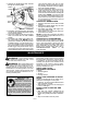
ASSEMBLY
WARNING: Stop engine and be sure
the impeller blades have stopped turning be-
fore opening the vacuum inlet door or at-
tempting to insert or remove the vacuum or
blower tubes. The rotating blades can cause
serious injury. Always disconnect the spark
plug before performing maintenance or ac-
cessing movable parts.
WARNING: If you receive your unit
assembled, check each step to insure your
unit is properly assembled and all fasteners
are secure. Follow all safety information in
the manual and on the unit.
D A standard screwdriver is required for as-
sembly.
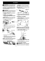
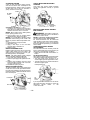
BLOWER TUBE ASSEMBLY
1. Align the rib on the upper blower tube with
the groove in the blower outlet; slide the
tube into place.
NOTE: Knob must be loose enough to allow
blower tube to be inserted in blower outlet. Loos-
en knob by turning counterclockwise.
Blower Outlet
Rib
Groove
2. Secure the tube by turning the knob clock-
wise.
3. Align the slots on the lower blower tube
with the tabs on the upper blower tube.
Upper Blower
Tube
Tab
Slot
Lower Blower
Tube
4. Slide the lower blower tube onto the upper
blower tube.
5. Turn the lower blower tube clockwise until
a click is felt to secure the lower blower
tube to the upper blower tube.
NOTE: When the upper and lower blower
tubes are assembled together properly, the
arrows on both tubes will be aligned.
6. To remove the tubes, turn the knob coun-
terclockwise to loosen the tubes; remove
the tubes.
HIGH --SPEED NOZZLE ASSEMBLY
When greater air speed is desired, use the
high--speed nozzle.
1. Align the slots on the nozzle with the tabs
on the lower blower tube.
High--Speed
Nozzle
Tab
Slot
Lower Blower
Tube
2. Slide the nozzle onto the lower blower tube.
3. Turn the nozzle clockwise until a click is
felt to secure the nozzle to the lower blow-
er tube.
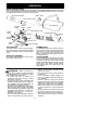
VACUUM BAG ASSEMBLY
1. Open the zipper on the vacuum bag and
insert the elbow tube.
2. Push the small end of the elbow tube
through the small opening in the bag.
Small Opening
Zipper
Opening
Elbow
Tube
Rib
NOTE: Make sure edge of the small opening
is flush against the flared area of the elbow tube,
and the rib on the elbow tube is on the bottom.
3. Close the zipper on the bag. Make sure the
zipper is closed completely.
4. Remove blower tubes from engine.
Rib
Groove
5. Insert the elbow tube into the blower outlet.
Make sure elbow tube rib is aligned with
the blower outlet groove.
6. Turn knob clockwise to secure elbow tube.
VACUUM TUBE ASSEMBLY
WARNING: Stop engine and be sure
the impeller blades have stopped turning before
opening the vacuum inlet door or attempting to

-- 6 --
insert or remove the vacuum or blower tubes.
The rotating blades can cause serious injury .
1. Insert the tip of a screwdriver into the latch
area of the vacuum inlet.
Latch
Area
Blower
Outlet
Vacuum Inlet Cover
Latch
A
rea
2. Gently tilt the handle of the screwdriver to-
ward the front of the unit to release the
latch while pulling up on the vacuum inlet
cover with your other hand.
3. Hold the vacuum inlet cover open until up-
per vacuum tube is installed.
Vacuum
Inlet
Cover
Vacuum Inlet
c
4. Align the tabs on the inside of the vacuum in-
let with the slots on the upper vacuum tube.
Tab
Slot
5. Push the upper vacuum tube into the vac-
uum inlet. Turn the tube counterclockwise
until a click is felt to secure the tube to the
blower unit.
6. Align slanted end of lower vacuum tube as
shown. Firmly push lower vacuum tube
into upper vacuum tube.
Slanted end of
lower vacuum tube
HOW TO CONVERT UNIT FROM
VACUUM USE TO BLOWER USE
WARNING: While blowing debris,
hold the unit with the muf fler side facing away
from your body and clothes (see OPERAT-
ING POSITION).
1. Remove the elbow tube and vacuum bag
by turning the knob counterclockwise to
loosen the elbow tube.
2. Remove the vacuum tubes by turning the
tubes clockwise.
3. Close the vacuum inlet cover and make
sure it is latched closed.
4. Reinstall the blower tubes (see BLOWER
TUBE ASSEMBLY).
VACUUM BAG SHOULDER STRAP
ADJUSTMENT
WARNING: While vacuuming debris,
hold the unit with the muf fler side facing away
from your body and clothes (see OPERAT-
ING POSITION).
1. Pass the shoulder strap over your head
and onto your right shoulder .
2. Extend your left arm toward the rear of the
vacuum bag.
3. Adjust shoulder strap until the vacuum
bag/shoulder strap seam lies between
your thumb and index finger.
4. Make sure air flows freely from the elbow
tube into bag. If bag is kinked, the unit will
not operate properly.

-- 7 --
OPERATION
KNOW YOUR BLOWER
READ THIS INSTRUCTION MANUAL AND SAFETY RULES BEFORE OPERA TING YOUR UNIT.
Compare the illustrations with your unit to familiarize yourself with the location of the various controls
and adjustments. Save this manual for future reference.
Choke Lever
Fuel Mix
Fill Cap
Starter
Rope
Throttle
Trigger
Spark
Plug
Upper Blower T ube
Primer
Bulb
Vacuum Handle
Lower Vacuum Tube
Upper Vacuum Tube
Vacuum Bag
Elbow Tube
High--Speed
Nozzle
Lower Blower Tube
STOP
Switch
STOP SWITCH
The STOP switch is used to stop the engine.
To stop the engine, push and hold the STOP
switch in the STOP position until the engine
stops.
THROTTLE TRIGGER
The THROTTLE TRIGGER is used to select
the desired engine speed.
PRIMER BULB
The PRIMER BULB removes air from the car-
buretor and fuel lines and fills them with fuel.
This allows you to start the engine with fewer
pulls on the starter rope. Activate primer
bulbby pressing it and allowing it to return to
its original position.
CHOKE LEVER
The CHOKE helps to supply fuel to the engine
toaidincoldstarting.Activatethechokeby
moving the choke lever to the FULL CHOKE
position. After engine attempts to start, move the
choke lever to the HALF CHOKE position.
Once engine starts, move choke lever to the
RUN posit ion.
OPERATING TIPS
WARNING: While vacuuming or
blowing debris, hold the unit with the muffler
side facing away from your body and clothes
(see OPERATING POSITION).
S To reduce the risk of hearing loss
associated with sound level(s), hearing
protection is required.
S To reduce the risk of injury associated with
contacting rotating parts, stop the engine be-
fore installing or removing attachments. Do
not operate without guard(s) in place.
S Operate power equipment only at reasonable
hours--not early in the morning or late at night
when people might be disturbed. Comply with
times listed in local ordinances. Usual recom-
mendations are 9:00 a.m. to 5:00 p.m.,
Monday though Saturday.
S To reduce noise levels, limit the number of
pieces of equipment used at any one time.
S To reduce noise levels, operate power
blowers at the lowest possible throttle
speed to do the job.
S Use rakes and brooms to loosen debris be-
fore blowing.
S In dusty conditions, slightly dampen sur-
faces or use a mister attachment when wa-
ter is available.
S Conserve water by using power blowers
instead of hoses for many lawn and garden
applications, including areas such as gutters,
screens, patios, grills, porches, and gardens.
S Watch out for children, pets, open windows,
or freshly washed cars. Blow debris away
safely.
S Use the full blower nozzle extension so the
air stream can work close to the ground.
S After using blowers and other equipment,
CLEAN UP! Dispose of debris in trash re-
ceptacles.

-- 8 --
OPERATING POSITION
WARNING: While vacuuming or
blowing debris, hold the unit with the muffler
side facing away from your body and clothes
(see following illustration).
Blower Vacuum
BEFORE STARTING ENGINE
WARNING: Be sure to read the fuel
information in the safety rules before you be-
gin. If you do not understand the safety rules,
do not attempt to fuel your unit. Call
1-800-554-6723.
FUELING ENGINE
WARNING: Remove fuel cap slowly
when refueling.
HELPFUL TIP
To obtain the correct oil mix
ratio, pour 3.2 ounces of
2--cycle synthetic oil into
one gallon of fresh gas.
This engine is certified to operate on
unleaded gasoline. Before operation,
gasoline must be mixed with a good quality
synthetic 2-cycle air-cooled engine oil
designed to be mixed at a ratio of 40:1. A 40:1
ratio is obtained by mixing 3.2 fluid ounces (95
ml) of oil with 1 gallon (4 liters) of unleaded
gasoline. Pour the entire contents of the 3.2
ounce (95 ml) container of oil into 1 gallon (4
liters) of gasoline to achieve the proper fuel
mixture. DO NOT USE automotive or marine
oil. These oils will cause engine damage.
When mixing fuel follow the instructions
printed on the container . Once oil i s added to
gasoline, shake container momentarily to
assure that the fuel is thoroughly mixed. Always
read and follow the safety rule s relating to fuel
before fueling your unit.
CAUTION : Never use straight gasoline in
your unit. This will cause permanent engine
damage and void the limited warranty.
FUEL REQUIREMENTS
This engine requires the use of minimum 87
octane [R+M]/2 clean gasoline.
IMPORTANT
Use of alcohol blended fuels (called gasohol or
using ethanol or methanol) can cause major
engine performance and durability problems.
WARNING: Alternative fuels (not gas-
oline) such as E--15 (15% alcohol), E--20 (20%
alcohol), E--85 (85% alcohol) are NOT classified
as gasoline and are NOT approved for use in
2--stroke gasoline engines. Use of alternative
fuels will cause problems such as: improper
clutch engagements, overheating, vapor lock,
power loss, lubrication deficiency , deterioration
of fuel lines, gaskets and internal carburetor
components, etc. Alternative fuels cause high
moisture absorption into the fuel/oil mixture
leading to oil and fuel separation.
HOW TO STOP YOUR ENGINE
D Release the throttle trigger.
S Push and hold the ST OP switch in the
STOP position until the engine stops.
HOW TO START YOUR ENGINE
WARNING: You MUST make sure
the tubes are secure before using the unit.
D Fuel engine. Move at least 10 feet (3 me-
ters) away from the fueling site.
D Hold the unit in the starting position as
shown. Make sure the blower end is di-
rected away from people, animals, glass,
and solid objects.
Blower
Vacuum
STARTING POSITION
WARNING: When starting engine,
hold the unit as illustrated. Do not set unit on any
surface except a clean, hard area when starting
engine or while engine is running. Debris such
as gravel, sand, dust, grass, etc. could be
picked up by the air intake and thrown out
through the discharge opening, damaging the
unit or property , or causing serious injury to by-
standers or the operator .
HELPFUL T IP
If your engine still does not
start after following these
instructions, please call
1--800--554--6723.
STARTING A COLD ENGINE (or warm
engine after runni ng out of fuel)
1. Slowly press the primer bulb 6 times.
2. Move choke lever to the FULL CHOKE posi-
tion.

-- 9 --
3. Squeeze the throttle trigger fully and hold
through all remaining steps.
Choke
Lever
Starter
Handle
Primer
Bulb
4. Pull starter rope handle sharply until engine
sounds as if it is trying to start, but do not pull
rope more than 6 times.
5. As soon as engine sounds as if it is trying to
start, move choke lever to HALF CHOKE
position.
6. Pull starter rope sharply until engine runs,
but no more than 6 pulls.
NOTE: If the en-
gine doesn’t start after 6 pulls (at the HALF
CHOKE position), move the choke lever to
the FULL CHOKE position and press the
primer bulb 6 times. Squeeze and hold the
throttle trigger and pull the starter rope 2
more times. Move the choke lever to the
HALF CHOKE position and pull the starter
rope until the engine runs, but no more
than 6 pulls. If the engine still doesn’t start,
it is probably flooded. Proceed to START-
ING A FLOODED ENGINE.
7. Once the engine starts, allow it to run 10 se-
conds, then move the choke lever to the
RUN position. Allow the unit to run for 30
more seconds at RUN before releasing the
throttle trigger .
NOTE: If engine dies with
the choke lever in the RUN position, move
the choke lever to the HALF CHOKE posi-
tion and pull the rope until engine runs, but
no more than 6 pulls.
STARTING A WARM ENGINE
1. Mo ve th e choke leve r to the HAL F CHOKE
position.
2. Squeeze the throttle trigger fully and hold
through all remaining steps.
3. Pull starter rope sharply until engi ne runs,
but no more than 6 pulls.
4. Allow engine to run 15 seconds, then move
the choke lever to RUN.
NOTE: If engine has not started, pull starter
rope 5 more pulls. If engine still does not run, it
is probably flooded.
STARTING A FLOODED ENGINE
Flooded engines can be started by placing the
choke lever in the RUN position; then, pull the
rope to clear the engine of excess fuel. This
could require pulling the starter handle many
times depending on how badly the unit is
flooded. If the unit still doesn’t start, refer to
TROUBLESHOOTING T ABL E or call
1-800-554-6723.
MAINTENANCE
WARNING: Avoid touching muffler
unless engine and muffler are cold. A hot
muffler can cause serious burns.
WARNING: Stop engine and be sure
the impeller blades have stopped turning be-
fore opening the vacuum inlet door or at-
tempting to insert or remove the vacuum or
blower tubes. The rotating blades can cause
serious injury. Always disconnect the spark
plug before performing maintenance or ac-
cessing movable parts.
HELPFUL TIP
IMPORTANT: Have all
repairs other than the rec-
ommended maintenance
described in the instruction
manual performed by an
authorized service dealer.
If any dealer other than an authorized
service dealer performs work on the
product, we may not pay for repairs un-
der warranty. It is your responsibility to
maintain and perform general mainte-
nance.
GENERAL RECOMMEND ATIONS
The warranty on this unit does not cover items
that have been subjected to operator abuse
or negligence. To receive full value from the
warranty , the operator must maintain unit as
instructed in this manual. Various adjust-
ments will need to be made periodically to
properly maintain your unit.
CHECK FOR LOOSE
FASTENERS AND PARTS
S Muffler
S Spark Plug Boot
S Air Filter
S Housing Screws
CHECK FOR DAMAGED OR WORN
PARTS
Contact an authorized service dealer for re-
placement of damaged or worn parts.
S Fuel Tank -- Do not use unit if fuel tank shows
signs of damage or leaks.
S Vacuum Bag -- Do not use vacuum bag if it
is torn or damaged.
INSPECT AND CLEAN UNIT AND
DECALS
S After each use, inspect complete unit for
loose or damaged parts. Clean the unit and
decals using a damp cloth with a mild deter-
gent.
S Wipe off unit with a clean dry cloth.

-- 1 0 --
CLEAN AIR FILTER
A dirty air filter decreases engine perform-
ance and increases fuel consumption and
harmful emissions. Always clean or replace
air filter after every 5 hours of operation or
yearly, whichever comes first.
Air Filter
Cover
A
ir Filter
Button
Cleaning the air filter:
1. Clean the cover and the area around it to
keep debris from falling into the carburetor
chamber when the cover is removed.
NOTE: Move choke lever to RUN position
before opening air filter cover .
2. Open air filter cover by pushing button
(see illustration). Remove air filter .
NOTE: Do not clean filter in gasoline or other
flammable solvent. Doing so can create a fire
hazard or produce harmful evaporative emis-
sions.
3. Wash the filter in soap and water.
4. Allow filter to dry.
5. Apply a few drops of oil to the filter;
squeeze filter to distribute oil.
6. Replace parts.
REPLACE SPARK PLUG
Replace spark plug each year to ensure the
engine starts easier and runs better. Set
spark plug gap at 0.025 inch (0.6 mm). Igni-
tion timing is fixed, nonadjustable.
NOTE: This spark ignition system complies
with the Canadian standard ICES--002.
1. Twist, then pull off spark plug boot.
2. Remove spark plug from cylinder and dis-
card.
3. Replace with Champion RCJ-6Y spark
plug and tighten securely with a 3/4 inch
(19 mm) socket wrench.
4. Reinstall the spark plug boot.
REPLACE FUEL FILT ER
To replace fuel filter , drain unit by running it dry
of fuel, then remove fuel cap/retainer assem-
bly from tank. Pull filter from tank and remove
it from the fuel line. Install new fuel filter on fuel
line; reinstall parts.
Fuel Line
Fuel Filter
CHECK MUFFLER MOUNTING
SCREWS
Once each year, ensure muffler mounting
screws are tightened securely to prevent
damage.
Muffler
Mounting
Screw
MUFFLER AND SPARK ARREST-
ING SCREEN
WARNING: The muffler on this prod-
uct contains chemicals known to the State of
California to cause cancer.
NOTE: THE SP ARK ARRESTING SCREEN
ON THIS UNIT IS NOT SERVICEABLE.
For normal homeowner use, the muffler and
spark arresting screen will not require replace-
ment. After 50 hours of use, we recommend
that your muffler be replaced by your authorized
service dealer.
CARBURETOR IDLE SPEED
ADJUSTMENT
The carburetor has been carefully set at the
factory . Adjustments may be necessary if you
notice any of the following conditions:
S Engine will not idle when the throttle is re-
leased.
To adjust idle speed:
Allow engine to idle. Adjust speed until engine
runs without stalling (idle speed too slow).
S Turn idle speed screw clockwise to in-
crease engine speed if engine stalls or dies.
S Turn idle speed screw counterclockwise to
decrease engine speed.
Air
Filter
Cover
Idle Speed Screw
If you require further assistance or are unsure
about performing this procedure, contact an
authorized service dealer or call
1--800--554--6723.

-- 1 1 --
STORAGE
WARNING: Perform the following
steps after each use:
S Allow engine to cool, and secure the unit
before storing or transporting.
S Store unit and fuel in a well ventilated area
where fuel vapors cannot reach sparks or
open flames from water heaters, electric
motors or switches, furnaces, etc.
S Store unit with all guards in place. Position
unit so that any sharp object cannot acci-
dentally cause injury.
S Store unit and fuel well out of the reach of
children.
SEASONAL STORAGE
Prepare unit for storage at end of season or if
it will not be used for 30 days or more.
If your unit is to be stored for a period of time:
S Clean the entire unit before lengthy stor-
age.
S Store in a clean dry area.
S Lightly oil external metal surfaces.
FUEL SYSTEM
Under FUELING ENGINE in the OPERA-
TION section of this manual, see message la-
beled IMPORT ANT regarding the use of ga-
sohol in your engine.
Fuel stabilizer is an acceptable alternative in
minimizing the formation of fuel gum deposits
during storage. Add stabilizer to gasoline in fuel
tank or fuel storage container . Follow the mix
instructions found on stabilizer container . Run
engine at least 5 minutes after adding stabilizer.
HELPFUL TIP
During storage of your gas/
oil mixture, the oil will sepa-
rate from the gas.
We recommend that you
shake the gas can weekly
to insure proper blending of
the gas and oil.
ENGINE
S Remove spark plug and pour 1 teaspoon of
40:1, 2-cycle engine oil (air cooled) through
the spark plug opening. Slowly pull the
starter rope 8 to 10 times to distribute oil.
S Replace spark plug with new one of recom-
mended type and heat range.
S Clean air filter.
S Check entire unit for loose screws, nuts,
and bolts. Replace any damaged, broken,
or worn parts.
S At the beginning of the next season, use
only fresh fuel having the proper gasoline to
oil ratio.
OTHER
S Do not store gasoline from one season to
another.
S Replace your gasoline can if it starts to rust.

-- 1 2 --
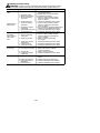
TROUBLE
CAUSE REMEDY
Engine will not
start.
1. Engine flooded.
2. Fuel tank empty .
3. Spark plug not firing.
4. Fuel not reaching
carburetor.
5. Compression low .
1. See “Starting a Flooded Engine”
in Operation section.
2. Fill tank with correct fuel mixture.
3. Install new spark plug.
4. Check for dirty fuel filter; replace.
Check for kinked or split fuel line;
repair or replace.
5. Contact an authorized service dealer.
Engine will not
idle properly.
1. Fuel not reaching
carburetor.
2. Carburetor requires
adjustment.
3. Crankshaft seals worn.
4. Compression low .
1. Check for dirty fuel filter; replace.
Check for kinked or split fuel line;
repair or replace.
2. See “Carburetor Idle Speed Adjustment”
in Service and Adjustments Section.
3. Contact an authorized service dealer
4. Contact an authorized service dealer.
1. Air filter dirty.
2. Fuel not reaching
carburetor.
3. Spark plug fouled.
4. Carburetor requires
adjustment.
5. Carbon build up.
6. Compression low .
Engine will not
accelerate,
lacks power , or
dies under a
load.
1. Clean or replace air filter .
2. Check for dirty fuel filter; replace.
Check for kinked or split fuel line;
repair or replace.
3. Clean or replace spark plug
and re-gap.
4. Contact an authorized service dealer.
5. Contact an authorized service dealer.
6. Contact an authorized service dealer.
Engine smokes
excessively.
1. Choke partially on.
2. Fuel mixture incorrect.
3. Air filter dirty.
4. Carburetor requires
adjustment.
1. Adjust choke.
2. Empty fuel tank and refill with
correct fuel mixture.
3. Clean or replace air filter.
4. Contact an authorized service dealer.
Engine runs hot.
1. Fuel mixture incorrect.
2. Spark plug incorrect.
3. Carburetor requires
adjustment.
4. Carbon build up.
1. See “Fueling Engine” in Operation
section.
2. Replace with correct spark plug.
3. Contact an authorized service dealer.
4. Contact an authorized service dealer.
TROUBLESHOOTING TABLE
WARNING: Always stop unit and disconnect spark plug before performing any of the
recommended remedies below other than remedies that require operation of the unit.

-- 1 3 --
LIMITED WARRANTY
McCulloch, a di vision of Hu sq var n a Consum e r
Outdoor Products N.A., Inc., warrants to the
original consumer purchaser that each new
McCulloch brand gasoline tool or attachment is
free from defects in material and workmanship
and agrees to repair or replace under this war-
ranty any defective gasoline product or attach-
ment as follows from the original date of pur-
chase.
2YEARS--Parts and Labor, when used for
household purposes.
90 DAYS -- Parts and Labor , when used for
commercial, professional, or income producing
purposes.
30 DA YS -- Parts and Labor, if used for rental
purposes.
This warranty is not transferable and does not
cover damage or liability caused by improper
handling, improper maintenance or alteration,
or the use of accessories and/or attachments
not specifically recommended by McCulloch
for this tool. This warranty does not cover
tune--up, spark plugs, filters, starter ropes, or
blower and vacuum tubes that will wear and
require replacement with reasonable use dur-
ing the warranty period. This warranty does
not cover pre--delivery setup or normal ad-
justments explained in the instruction manu-
al. This warranty does not cover transporta-
tion costs.
In the event you have a claim under this warran-
ty, you must return the product to an authorized
service dealer .
Should you have any unanswered questions
concerning this warranty, please contact:
McCulloch, a division of Husqvarna
Consumer Outdoor Products N.A., Inc.
9335 Harris Corners
Charlotte, NC 28269
1--800--554--6723
In Canada, contact:
McCulloch
850 Matheson Blvd. West
Mississauga, Ontario L5V 0B4
Giving the model number , serial number and
date of purchase of your product and the name
and address of the authorized dealer from
whom it was purchased.
THIS WARRANTY GIVES YOU SPECIFIC
LEGAL RIGHTS, AND YOU MAY HAVE OTH-
ER RIGHTS WHICH VARY FROM ST A T E TO
STA TE .
NO CLAIMS FOR CONSEQUENTIAL OR
OTHER DAMAGES WIL L BE ALLOWE D,
AND THERE ARE NO OTHER EXPRESS
WARRANTIES EXCEPT THOSE EX-
PRESSL Y STIPULA TED HEREIN.
SOME ST ATES DO NOT ALLOW LIMITA-
TIONS ON HOW LONG AN IMPL I ED WAR-
RANTY L AS TS OR T HE EX CL USI ON OR
LIMITATIONS OF INCIDENTAL OR CONSE-
QUENTIAL DAMAGES, SO THE ABOVE LIM-
ITA TIONS OR EXCLUSION MAY NOT APPL Y
TO YOU.
This is a limited warranty within the meaning of
that term as defined in the Magnuson--Moss Act
of 1975.
The policy of McCulloch is to continuously
improve its products. Therefore, McCulloch
reserves the right to change, modify, or dis-
continue models, designs, specifications,
and accessories of all products at any time
without notice or obligation to any purchaser.
U.S. EPA/CALIFORNIA/ENVIRONMENT CANADA
EMISSION CONTROL WARRANTY STATEMENT
YOUR WARRANTY RIGHTS AND OB-
LIGATIONS: The U.S. Environmental
Protection Agency, California Air Resources
Board, Environment Canada and McCulloch
are pleased to explain the emissions control
system warranty on your year 2010 and later
small off--road engine. In California, all small of f--
road engines must be designed, built, and
equipped t o m eet t he State’ s stringe nt anti--
smog standards. McCulloch must warrant the
emission control system on your small off--
road engine for the periods of time listed be-
low provided there has been no abuse, ne-
glect, or improper maintenance of your small
off--road engine. Your emission co ntr ol syst em
includes parts such as the carburetor , the igni-
tion system and the fuel tank. Where a warrant-
able condition exists, McCulloch will repair
your small off--road engine at no cost to you.
Expenses covered under warranty include
diagnosis, parts and labor.
MANUFACTURER’S WARRANTY COV-
ERAGE: If any emissions related part on your
engine (as listed under Emissions Contro l
Warranty Parts List) is defective or a defect in
the materi als or workmanship of the en gine
causes the failure of such an emission related
part, the part will be repaired or replaced by
McCulloch. OWNER’S WARRAN TY RE-
SPONSIBILITIES: As the small off--road en-
gine owner , you are responsible for the per-
formance of the required maintenance listed
in your instruction manual. McCulloch recom-
mends that you retain all receipts covering
maintenance on your small off--road engine,
but McCulloch cannot deny warranty solely
for the lack of receipts or for your failure to en-
sure the performance of all scheduled main-
tenance. As the small off--road engine owner,
you should be aware that McCulloch may
deny you warranty coverage if your small off--
road engine or a part of it has failed due to

-- 1 4 --
abuse, neglect, improper maintenance, un-
approved modifications, or the use of parts
not made or approved by the original equip-
ment manufacturer. You ar e responsible for
presenting your small off--road engine to an
McCulloch authorized repair center as soon as
a problem exists. Warranty repairs should be
completed in a reasonable amount of time, not
to ex cee d 3 0 d ays. If you have any questions
regarding your warranty rights and responsi-
bilities, you sho uld co ntact yo ur nearest autho-
rized service center , call McCulloch at
1--800--554--6723, or send e-mail correspon-
dence to
emission.warranty@HCOP--
emission.com
. WARRANTY COMMENCE-
MENT DATE: The warranty period begins on
the date the small off--road engine is pur-
chased. LENGTH OF C OVERAGE: This
warranty shall be for a period of two years
from the initial date of purchase, or until the
end of the product warranty (whichever is lon-
ger). WHATIS COVERED: REPAIR OR RE-
PLACEMENTOF PARTS.Repair or replace-
ment of any warranted part will be performed
at no charge to the owner at an approved
McCulloch servicing center. If you have any
questions regarding your warranty rights and
responsibilities, you should contact your near-
est authorized service ce nter , call McCulloch
at 1--800--554--6723, or send e-mail corre-
spondence to
emission.warranty@HCOP--
emission.com
. WARRANTY PERIOD: Any
warranted part which is not scheduled for re-
placement as required maintenance, or which
is scheduled only for regular inspection to the ef-
fect of “repair or replace as necessary” shall be
warranted for 2 years. Any warranted part which
is scheduled for replacement as required main-
tenance shall be warranted for the period of time
up to the first scheduled replacement point for
that part. DIAGNOSIS: The owner shall not be
charged for diagnostic labor which leads to the
determi nation that a warranted part is defective
if the diagnostic work is performed at an ap-
proved McCulloch servicing center. CONSE-
QUENTIAL DAMAGES: McCulloch may be li-
able fo r damages to other engine components
caused by the failure of a warranted part still
under warranty. WHAT IS NOT COVERED:
All failures caused by abuse, neglect, or im-
proper maintenance are not covered. AD D--
ON OR MODIFIED PARTS: The use of add--
on or modified parts can be grounds for disal-
lowing a warranty claim. McCulloch is not li-
able to cover failures of warranted parts
caused by the use of add--on or modified
parts. HOW TO FILE A CLAIM: If you have
any questions regarding your warranty rights
and responsibilities, you should contact your
nearest authorized service center, call
McCulloch at 1--800--554--6723, or send
e-mail correspondence to
emission.warranty
@HCOP--emission. com
. WHERE TO GET
WARRANTY SERVICE: Warranty services
or repairs shall be provided at all McCulloch
service centers. Call: 1--800--554--6723 or
send e-mail correspondence to
emission.
warranty@HCOP--emission.com
. MAINTE-
NANCE, REPLACEMENT AND REPAIR
OF EMISSION RELA TED PARTS:Any
McCulloch approved replacement part used
in the performance of any warranty mainte-
nance or repair on emission related parts will
be provided without charge to the owner if the
part is under warranty. EMISSION CON-
TROL WARRANTY PARTS LIST: Carbure-
tor, air filter (covered up to maintenance
schedule), ignition system: spark plug (cov-
ered up to maintenance schedule), ignition
module, m uffler including catalyst (if
equipped), fuel tank. MAINTENANCE
STATEMENT: The owner is responsible for
the performance of all required maintenance
as defined in the instruction manual.
The information on the product label indicates which standard your engine is certified.
Example: (Year) EPA and/or CALIFORNIA.
This engine is certified to be emissions compliant for the following use:
Moderate (50 hours)
Intermediate (125 hours)
Extended (300 hours)
-
 1
1
-
 2
2
-
 3
3
-
 4
4
-
 5
5
-
 6
6
-
 7
7
-
 8
8
-
 9
9
-
 10
10
-
 11
11
-
 12
12
-
 13
13
-
 14
14


McCulloch MC200VS User manual
- Category
- Air blowers/dryers
- Type
- User manual
Ask a question and I''ll find the answer in the document
Finding information in a document is now easier with AI
Related papers
Other documents
-
Weed Eater SM400 User manual
-
-
Weed Eater 530165303-01 User manual
-
-
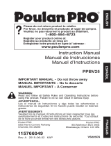 Poulan Pro PPBV25 2 Cycle Gas 450 CFM 230 MPH Hanheld Leaf Blower and Home Vacuum Owner's manual
-
-
-
Poulan 115350727 User manual
-
-
