Dual MS6130 User manual

Category
Microwaves
Type
User manual

This manual is also suitable for

R-1600
R-1601
R-1602
In the interest of user-safety the oven should be restored to its original
condition and only parts identical to those specified should be used.
WARNING TO SERVICE PERSONNEL: Microwave ovens con-
tain circuitry capable of producing very high voltage and
current. Contact with the following parts may result in a
severe, possibly fatal, electrical shock. (High Voltage Capaci-
tor, High Voltage Power Transformer, Magnetron, High Volt-
age Rectifier Assembly, High Voltage Harness etc..)
TABLE OF CONTENTS
Page
PRECAUTIONS TO BE OBSERVED BEFORE AND DURING SERVICING TO
AVOID POSSIBLE EXPOSURE TO EXCESSIVE MICROWAVE ENERGY...................INSIDE FRONT COVER
BEFORE SERVICING ......................................................................................................INSIDE FRONT COVER
WARNING TO SERVICE PERSONNEL................................................................................................................1
MICROWAVE MEASUREMENT PROCEDURE ...................................................................................................2
FOREWORD AND WARNING...............................................................................................................................3
PRODUCT SPECIFICATIONS ..............................................................................................................................4
GENERAL INFORMATION...................................................................................................................................4
OPERATION..........................................................................................................................................................7
TROUBLESHOOTING GUIDE ............................................................................................................................11
TEST PROCEDURE............................................................................................................................................12
TOUCH CONTROL PANEL ASSEMBLY ............................................................................................................21
COMPONENT REPLACEMENT AND ADJUSTMENT PROCEDURE ................................................................26
PICTORIAL DIAGRAM ........................................................................................................................................34
POWER UNIT CIRCUIT ......................................................................................................................................35
LSI UNIT CIRCUIT...............................................................................................................................................36
INDICATOR CIRCUIT..........................................................................................................................................37
PRINTED WIRING BOARD .................................................................................................................................38
PARTS LIST ........................................................................................................................................................39
PACKING AND ACCESSORIES .........................................................................................................................44
S4910R1600X//
R-1600
R-1601
R-1602
OVER THE RANGE
MICROWAVE OVEN
MODELS
SERVICE MANUAL
SHARP CORPORATION
This document has been published to be used for after
sales service only.
The contents are subject to change without notice.
SENSOR DEFROST TURNTABLE COOK
OFF
HELP
12345
6
7890
CUSTOM 
HELP
1 Coffee/tea
2 Roll/muffin, fresh
3 Roll/muffin, frozen
4 Hot cereal
5 Scrambled eggs
1 Dinner plate
2 Pasta/casserole
3 Frozen entree
4 Frozen snack
5 Pizza, slice
1 Baked potatoes
2 Fresh vegetables
3 Frozen vegetables
4 Rice
5 Ground meat
6 Fish/Seafood
7 Chicken breasts
8 Turkey breast
9 Roast pork
0 Meat loaf
POPCORN
COMPU 
DEFROST
POWER
LEVEL
TIMER
CLOCK
MINUTE
PLUS
MEMORY
COOK
STOP
CLEAR
START
TOUCH ON
TURNTABLE
ON/OFF
WORK
LIGHT
NIGHT
LIGHT
FAN
HI/LO
BREAKFAST
LUNCH
DINNER
R-1600
R-1601
R-1602
PRECAUTIONS TO BE OBSERVED BEFORE AND
DURING SERVICING TO AVOID POSSIBLE
EXPOSURE TO EXCESSIVE MICROWAVE
ENERGY
(a) Do not operate or allow the oven to be operated with the door open.
(b) Make the following safety checks on all ovens to be serviced before activating the magnetron or other
microwave source, and make repairs as necessary: (1) interlock operation, (2) proper door closing, (3)
seal and sealing surfaces (arcing, wear, and other damage), (4) damage to or loosening of hinges and
latches, (5) evidence of dropping or abuse.
(c) Before turning on microwave power for any service test or inspection within the microwave generating
compartments, check the magnetron, wave guide or transmission line, and cavity for proper alignment,
integrity, and connections.
(d) Any defective or misadjusted components in the interlock, monitor, door seal, and microwave
generation and transmission systems shall be repaired, replaced, or adjusted by procedures described
in this manual before the oven is released to the owner.
(e) A microwave leakage check to verify compliance with the Federal Performance Standard should be
performed on each oven prior to release to the owner.
BEFORE SERVICING
Before servicing an operative unit, perform a microwave emission check as per the Microwave
Measurement Procedure outlined in this service manual.
If microwave emissions level is in excess of the specified limit, contact SHARP ELECTRONICS
CORPORATION immediately @1-800-237-4277.
If the unit operates with the door open, service person should 1) tell the user not to operate the oven
and 2) contact SHARP ELECTRONICS CORPORATION and Food and Drug Administration's
Center for Devices and Radiological Health immediately.
Service personnel should inform SHARP ELECTRONICS CORPORATION of any certified unit found
with emissions in excess of 4mW/cm
2
. The owner of the unit should be instructed not to use the unit
until the oven has been brought into compliance.
1
R-1600
R-1601
R-1602
WARNING TO SERVICE PERSONNEL
Microwave ovens contain circuitry capable of pro-
ducing very high voltage and current, contact with
following parts
may result in a severe, possibly
fatal, electrical shock.
(Example)
High Voltage Capacitor, High Voltage Power Trans-
former, Magnetron, High Voltage Rectifier Assem-
bly, High Voltage Harness etc..
Read the Service Manual carefully and follow all
instructions.
Before Servicing
1. Disconnect the power supply cord , and then
remove outer case.
2. Open the door and block it open.
3. Discharge high voltage capacitor.
WARNING:RISK OF ELECTRIC SHOCK.
DISCHARGE THE HIGH-VOLTAGE
CAPACITOR BEFORE SERVICING.
The high-voltage capacitor remains charged about 60
seconds after the oven has been switched off. Wait for 60
seconds and then short-circuit the connection of the high-
voltage capacitor (that is the connecting lead of the high-
voltage rectifier) against the chassis with the use of an
insulated screwdriver.
Whenever troubleshooting is performed the power supply
must be disconnected. It may in, some cases, be necessary
to connect the power supply after the outer case has been
removed, in this event,
1. Disconnect the power supply cord, and then remove
outer case.
2. Open the door and block it open.
3. Discharge high voltage capacitor.
4. Disconnect the leads to the primary of the power
transformer.
5. Ensure that these leads remain isolated from other
components and oven chassis by using insulation tape.
6. After that procedure, reconnect the power supply cord.
When the testing is completed,
1. Disconnect the power supply cord, and then remove
outer case.
2. Open the door and block it open.
3. Discharge high voltage capacitor.
4. Reconnect the leads to the primary of the power
transformer.
5. Reinstall the outer case (cabinet).
6. Reconnect the power supply cord after the outer case is
installed.
7. Run the oven and check all functions.
After repairing
1. Reconnect all leads removed from components during
testing.
2. Reinstall the outer case (cabinet).
3. Reconnect the power supply cord after the outer case is
installed.
4. Run the oven and check all functions.
Microwave ovens should not be run empty. To test for the
presence of microwave energy within a cavity, place a cup
of cold water on the oven turntable, close the door and set
the power to HIGH and set the microwave timer for two (2)
minutes. When the two minutes has elapsed (timer at zero)
carefully check that the water is now hot. If the water
remains cold carry out Before Servicing procedure and re-
examine the connections to the component being tested.
When all service work is completed and the oven is fully
assembled, the microwave power output should be checked
and microwave leakage test should be carried out.
Don't Touch !
Danger High Voltage
2
R-1600
R-1601
R-1602
MICROWAVE MEASUREMENT PROCEDURE
A. Requirements:
1) Microwave leakage limit (Power density limit): The power density of microwave radiation emitted by a microwave oven
should not exceed 1mW/cm
2
at any point 5cm or more from the external surface of the oven, measured prior to acquisition
by a purchaser, and thereafter (through the useful life of the oven), 5 mW/cm
2
at any point 5cm or more from the external
surface of the oven.
2) Safety interlock switches Primary interlock relay and door sensing switch shall prevent microwave radiation emission in
excess of the requirement as above mentioned, secondary interlock switch shall prevent microwave radiation emission
in excess of 5 mW/cm
2
at any point 5cm or more from the external surface of the oven.
B. Preparation for testing:
Before beginning the actual measurement of leakage, proceed as follows:
1) Make sure that the actual instrument is operating normally as specified in its instruction booklet.
Important:
Survey instruments that comply with the requirement for instrumentation as prescribed by the performance standard
for microwave ovens, 21 CFR 1030.10(c)(3)(i), must be used for testing.
2) Place the oven tray in the oven cavity.
3) Place the load of 275±15 ml (9.8 oz) of tap water initially at 20±5˚C (68˚F) in the center of the oven cavity.
The water container shall be a low form of 600 ml (20 oz) beaker with an inside diameter of approx. 8.5 cm (3-1/2 in.)
and made of an electrically nonconductive material such as glass or plastic.
The placing of this standard load in the oven is important not only to protect the oven, but also to insure that any leakage
is measured accurately.
4) Set the cooking control on Full Power Cooking Mode
5) Close the door and select a cook cycle of several minutes. If the water begins to boil before the survey is completed,
replace it with 275 ml of cool water.
C. Leakage test:
Closed-door leakage test (microwave measurement)
1) Grasp the probe of the survey instrument and hold it perpendicular to the gap between the door and the body of the oven.
2) Move the probe slowly, not faster than 1 in./sec. (2.5 cm/sec.) along the gap, watching for the maximum indication on
the meter.
3) Check for leakage at the door screen, sheet metal seams and other accessible positions where the continuity of the metal
has been breached (eg., around the switches, indicator, and vents).
While testing for leakage around the door pull the door away from the front of the oven as far as is permitted by the closed
latch assembly.
4) Measure carefully at the point of highest leakage and make sure that the highest leakage is no greater than 4mW/cm
2
,
and that the secondary interlock switch does turn the oven OFF before any door movement.
NOTE: After servicing, record data on service invoice and microwave leakage report.
3
R-1600
R-1601
R-1602
SHARP ELECTRONICS CORPORATION
SHARP PLAZA, MAHWAH,
NEW JERSEY 07430-2135
SERVICE MANUAL
OVER THE RANGE
MICROWAVE OVEN
R-1600 / R-1601 / R-1602
FOREWORD
This Manual has been prepared to provide Sharp Electronics Corp.
Service Personnel with Operation and Service Information for the
SHARP OVER THE RANGE MICROWAVE OVEN, R-1600, R-1601,
R-1602.
It is recommended that service personnel carefully study the entire
text of this manual so that they will be qualified to render satisfactory
customer service.
Check the interlock switches and the door seal carefully. Special
attention should be given to avoid electrical shock and microwave
radiation hazard.
WARNING
Never operate the oven until the following points are ensured.
(A) The door is tightly closed.
(B) The door brackets and hinges are not defective.
(C) The door packing is not damaged.
(D) The door is not deformed or warped.
(E) There is not any other visible damage with the oven.
Servicing and repair work must be carried out only by trained service
personnel.
DANGER
Certain initial parts are intentionally not grounded and present
a risk of electrical shock only during servicing. Service
personnel - Do not contact the following parts while the
appliance is energized;
High Voltage Capacitor, Power Transformer, Magnetron, High
Voltage Rectifier Assembly, High Voltage Harness;
If provided, Vent Hood, Fan assembly, Cooling Fan Motor.
All the parts marked “*” on parts list are used at voltages more than
250V.
Removal of the outer wrap gives access to voltage above 250V.
All the parts marked “” on parts list may cause undue microwave
exposure, by themselves, or when they are damaged, loosened
or removed.
PRODUCT DESCRIPTION
GENERAL INFORMATION
OPERATION
TROUBLESHOOTING GUIDE AND
TEST PROCEDURE
TOUCH CONTROL PANEL
COMPONENT REPLACEMENT
AND ADJUSTMENT PROCEDURE
WIRING DIAGRAM
PARTS LIST
4
R-1600
R-1601
R-1602
ITEM DESCRIPTION
Power Requirements 120 Volts / 14 Amperes
60 Hertz
Single phase, 3 wire grounded
Power Output 1000 watts (IEC-705 TEST PROCEDURE)
Operating frequency of 2450MHz
Case Dimensions Width 29-15/16"
Height 16-3/8"
Depth 15- 1/16" (Not including the door handle)
Cooking Cavity Dimensions Width 21"
Height 8-7/8"
1.6 Cubic Feet Depth 14-7/16"
Hood lamp 2 bulbs, 20W x 2, Incandescent light bulbs
Hood fan Approx. 300 C.F.M.
Control Complement Touch Control System
Clock ( 1:00 - 12:59 )
Timer (0 - 99 min. 99 seconds)
Microwave Power for Variable Cooking
Repetition Rate;
P-HI..................................................Full power throughout the cooking time
P-90 .................................................................... approx. 90% of Full Power
P-80 .................................................................... approx. 80% of Full Power
P-70 .................................................................... approx. 70% of Full Power
P-60 .................................................................... approx. 60% of Full Power
P-50 .................................................................... approx. 50% of Full Power
P-40 .................................................................... approx. 40% of Full Power
P-30 .................................................................... approx. 30% of Full Power
P-20 .................................................................... approx. 20% of Full Power
P-10 .................................................................... approx. 10% of Full Power
P-0 .................................................... No power throughout the cooking time
CUSTOM HELP pad, BREAKFAST pad, LUNCH pad, DINNER pad
POPCORN pad, COMPU DEFROST pad, MEMORY COOK pad
Number selection pads, POWER LEVEL pad, TIMER / CLOCK pad
MINUTE PLUS pad, TURNTABLE ON / OFF pad, START / TOUCH ON pad
WORK LIGHT pad, NIGHT LIGHT pad, FAN HI / LO pad, STOP/CLEAR pad
Oven Cavity Light 20W x 1 Incandescent light bulb
Safety Standard UL Listed FCC Authorized
DHHS Rules, CFR, Title 21, Chapter 1, Subchapter J
Weight Approx. 56 lbs.
PRODUCT SPECIFICATION
GENERAL INFORMATION
GROUNDING INSTRUCTIONS
This oven is equipped with a three prong grounding plug. It must be plugged into a wall receptacle that is properly installed
and grounded in accordance with the National Electrical Code and local codes and ordinances.
In the event of an electrical short circuit, grounding reduces the risk of electric shock by providing an escape wire for the
electric current.
WARNING: Improper use of the grounding plug can result in a risk of electric shock.
5
R-1600
R-1601
R-1602
Electrical Requirements
The oven is equipped with a 3-prong grounding plug. DO NOT UNDER ANY CIRCUMSTANCES CUT OR REMOVE THE
GROUNDING PIN FROM THE PLUG.
The power supply cord and plug must be connected to a separate 120 Volt AC, 60 Hz, 15 Amp. or more dedicated line, using
a grounded receptacle. The receptacle should be located inside the cabinet directly above the Microwave Oven/Hood
system mounting location.
OVEN DIAGRAM
1. Oven door with see-through window.
2. Door hinges.
3. Stirrer cover.
4. Turntable motor shaft.
5. Oven lamp.
It will light when oven is operating or door is open.
6. Door latches.
The oven will not operate unless the door is securely closed.
7. Auto-Touch control panel.
8. Time display: Digital display, 99 minutes 99 seconds.
9. Ventilation openings.
10.Light Cover.
11.Grease filters.
12.Removable turntable.
The turntable will rotate clockwise or counterclockwise.
Only remove for cleaning.
13.Removable turntable support.
14. Power supply cord
3-Pronged Plug
Grounded
Receptacle Box
Grounding Pin
3-Pronged Receptacle
10
11
12
8
7
14
6
9
3
4
5
1
9
13
2
6
R-1600
R-1601
R-1602
CONTROL PANEL
DEFROST TURNTABLE COOK
OFF
HELP
12345
67890
CUSTOM 
HELP
1 Coffee/tea
2 Rolls/muffins, fresh
3
Rolls/muffins, frozen
4 Hot cereal
5 Scrambled eggs
1 Dinner plate
2 Pasta/casserole
3 Frozen entrees
4 Frozen snacks
5 Pizza, slice
1 Baked potatoes
2 Fresh vegetables
3 Frozen vegetables
4 Rice
5 Ground meat
6 Fish/seafood
7 Chicken breasts
8 Turkey breast
9 Roast pork
0 Meat loaf
POPCORN
COMPU 
DEFROST
POWER
LEVEL
TIMER
CLOCK
MINUTE
PLUS
MEMORY
COOK
STOP
CLEAR
START
TOUCH ON
TURNTABLE
ON/OFF
WORK
LIGHT
NIGHT
LIGHT
FAN
HI/LO
BREAKFAST
LUNCH
DINNER
7
R-1600
R-1601
R-1602
OPERATION
DESCRIPTION OF OPERATING SEQUENCE
The following is a description of component functions during
oven operation.
OFF CONDITION
Closing the door activates the door sensing switch and
secondary interlock switch. (In this condition, the monitor
switch contacts are opened.)
When oven is plugged in, 120 volts A.C. is supplied to the
control unit. (Figure O-1).
1. The display will show "SHARP SIMPLY THE BEST
PRESS CLEAR AND PRESS CLOCK".
To set any program or set the clock, you must first touch
the STOP/CLEAR pad. The display will clear, and " : "
will appear .
COOKING CONDITION
Program desired cooking time touching the NUMBER pads.
When the START pad is touched, the following operations
occur:
1. The contacts of relays are closed and components
connected to the relays are turned on as follows.
(For details, refer to Figure O-2)
RELAY CONNECTED COMPONENTS
RY1 Oven lamp / Fan motor / Stirrer motor
RY2 Power transformer
RY3 Turntable motor
RY4 Hood fan motor
2. 120 volts A.C. is supplied to the primary winding of the
power transformer and is converted to about 3.3 volts
A.C. output on the filament winding, and approximately
2000 volts A.C. on the high voltage winding.
3. The filament winding voltage heats the magnetron
filament and the H.V. winding voltage is sent to a voltage
doubler circuit.
4. The microwave energy produced by the magnetron is
channelled through the waveguide into the cavity feed-
box, and then into the cavity where the food is placed to
be cooked.
5. Upon completion of the cooking time, the power
transformer, oven lamp, etc. are turned off, and the
generation of microwave energy is stopped. The oven
will revert to the OFF condition.
6. When the door is opened during a cook cycle, monitor
switch, door sensing switch, secondary interlock switch
and primary interlock relay are activated with the following
results. The circuits to the stirrer motor, the cooling fan
motor, the turntable motor, and the high voltage
components are de-energized, and the digital read-out
displays the time still remaining in the cook cycle when
the door was opened.
7. The monitor switch is electrically monitoring the operation
of the secondary interlock switch and primary interlock
relay (RY2) and is mechanically associated with the door
so that it will function in the following sequence.
(1) When the door opens from a closed position, the
primary interlock relay and secondary interlock switch
open their contacts, and then the monitor switch
contacts close.
(2) When the door is closed from the open position, the
monitor switch contacts first open, and then the
contacts of the secondary interlock switch and door
sensing switch close.
If the secondary interlock switch and primary interlock relay
(RY2) fail with their contacts closed when the door is
opened, the closing of the monitor switch contacts will form
a short circuit through the monitor fuse, secondary interlock
switch and primary interlock relay (RY2), causing the moni-
tor fuse to blow.
POWER LEVEL P-0 TO P-90 COOKING
When Variable Cooking Power is programmed, the 120
volts A.C. is supplied to the power transformer intermittently
through the contacts of relay (RY2) which is operated by the
control unit within an interval second time base. Microwave
power operation is as follows:
VARI-MODE ON TIME OFF TIME
Power 10(P-HI) 32 sec. 0 sec.
(100% power)
Power 9(P-90) 30 sec. 2 sec.
(approx. 90% power)
Power 8(P-80) 26 sec. 6 sec.
(approx. 80% power)
Power 7(P-70) 24 sec. 8 sec.
(approx. 70% power)
Power 6(P-60) 22 sec. 10 sec.
(approx. 60% power)
Power 5(P-50) 18 sec. 14 sec.
(approx. 50% power)
Power 4(P-40) 16 sec. 16 sec.
(approx. 40% power)
Power 3(P-30) 12 sec. 20 sec.
(approx. 30% power)
Power 2(P-20) 8 sec. 24 sec.
(approx. 20% power)
Power 1(P-10) 6 sec. 26 sec.
(approx. 10% power)
Power 0(P-0) 0 sec. 32 sec.
(0% power)
Note: The ON/OFF time ratio does not correspond with
the percentage of microwave power, because
approx. 2 seconds are needed for heating of the
magnetron filament.
8
R-1600
R-1601
R-1602
3. RE-CIRCULATION (INSIDE VENTING)
The air handing is the same as VERTICAL VENTING
except that the final air discharge is directed horizontally
through the upper front of the oven into the kitchen. IN
this case, the accessory charcoal filter RK-230 must be
provided to filter the air before it leaves the oven.
_: AIR FLOW
2. HORIZONTAL VENTING
The air handing is the same as VERTICAL VENTING
except that the final air discharge is directed horizontally
out from the top rear of the oven into the customer's vent
system.
_: AIR FLOW
GREASE 
FILTER
HOOD FAN MOTOR
TO DUCT
TO DUCT
HOOD 
INTAKE 
DUCT
HOOD 
INTAKE 
DUCT
HOOD FAN MOTOR
GREASE 
FILTER
TO DUCT
HOOD 
INTAKE 
DUCT
HOOD EXHAUST 
LOUVER
HOOD FAN MOTOR
CHARCOAL 
FILTER
BREAKFIRST, LUNCH, DINNER
BREAKFIRST, LUNCH, DINNER will automatically com-
pute the microwave power and cooking time. Set the desired
program by touching one of the BREAKFIRST, LUNCH,
DINNER pads, and number pad to select menu. Enter the
weight or quantity by touching the Number pads. When the
START pad is touched, the following operations occur:
1. The COOK indicator will light.
2. The cooking time will appear on the display and start
counting down to zero. The cooking time is adjusted
automatically according to the weight of the food.
3. The shut-off relays (RY1, RY2 and RY3) are energized,
turning on the oven lamp, turntable motor, cooling fan
motor and convection motor. The power supply voltage
is applied to the heating element.
4. Now, the oven is in the microwave cooking mode.
COMPU DEFROST COOKING
The COMPU DEFROST key is a special function key to
defrost meats and poultry faster and better. COMPU DE-
FROST automatically defrosts roast beef, etc.. Touch the
COMPU COOK pad and number pad to select menu and
enter the food weight by touching the number pads. When
the START pad is touched, the oven will cook according to
the special cooking sequence.
VENTILATION METHODS HOT AIR EXHAUST
1. VERTICAL VENTING
For this venting method, hot air rising from the
conventional range below is drawn in by the hood fan
motor through the grease filters at the right and left sides
of the base cover, up through the right and left sides of
the oven cavity, then discharged vertically at rear center
top of the oven, into the customer's vent system.
_: AIR FLOW
9
R-1600
R-1601
R-1602
SCHEMATIC
NOTE: CONDITION OF OVEN
1. DOOR CLOSED
2. COOKING TIME PROGRAMMED
3. VARIABLE COOKING CONTROL "HIGH"
4. "START" PAD TOUCHED
Figure O-2. Oven Schematic-Cooking Condition
Figure O-1. Oven Schematic-Off Condition
SCHEMATIC
NOTE: CONDITION OF OVEN
1. DOOR CLOSED
2. CLOCK APPEARS ON DISPLAY
MAGNETRON 
TEMPERATURE FUSE
FUSE 
20A
TURNTABLE
MOTOR
FAN
MOTOR
STIRRER
MOTOR
MAGNETRON
OVEN LAMP
MONITOR
SWITCH
BLKWHT
POWER
TRANSFORMER
HIGH VOLTAGE
CAPACITOR
0.94µF
HIGH VOLTAGE
RECTIFIER
COM. N.O.
COM.
CONTROL UNIT
GND
GRN
HOOD
MOTOR
B7
B5
B3
B1
Low
High
A1 A3 B9 A7 A5 N.O.
E1
E2
DOOR
SENSING
SWITCH
SECONDARY
INTERLOCK
SWITCH
120 V AC.
60 Hz
HOOD
LAMP
HL HL
RY3 RY1
RY2
PRIMARY
INTERLOCK 
RELAY
FM
STM
OL
TTM
HOOD FAN
THERMAL
CUT OUT
HOOD
CAPACITOR
RY4
RY5
N.C.
CAVITY 
THERMAL CUT-OUT
SSR
MAGNETRON 
TEMPERATURE FUSE
FUSE 
20A
TURNTABLE
MOTOR
FAN
MOTOR
STIRRER
MOTOR
MAGNETRON
OVEN LAMP
MONITOR
SWITCH
BLKWHT
POWER
TRANSFORMER
HIGH VOLTAGE
CAPACITOR
0.94µF
HIGH VOLTAGE
RECTIFIER
COM. N.O.
COM.
CONTROL UNIT
GND
GRN
HOOD
MOTOR
B7
B5
B3
B1
A1 A3 B9 A7 A5 N.O.
E1
E2
DOOR
SENSING
SWITCH
SECONDARY
INTERLOCK
SWITCH
120 V AC.
60 Hz
HOOD
LAMP
HL HL
RY3 RY1
RY2
PRIMARY
INTERLOCK 
RELAY
FM
STM
OL
TTM
HOOD FAN
THERMAL
CUT OUT
HOOD
CAPACITOR
RY4
RY5
N.C.
CAVITY 
THERMAL CUT-OUT
SSR
Low
High
10
R-1600
R-1601
R-1602
DESCRIPTION AND FUNCTION OF COMPONENTS
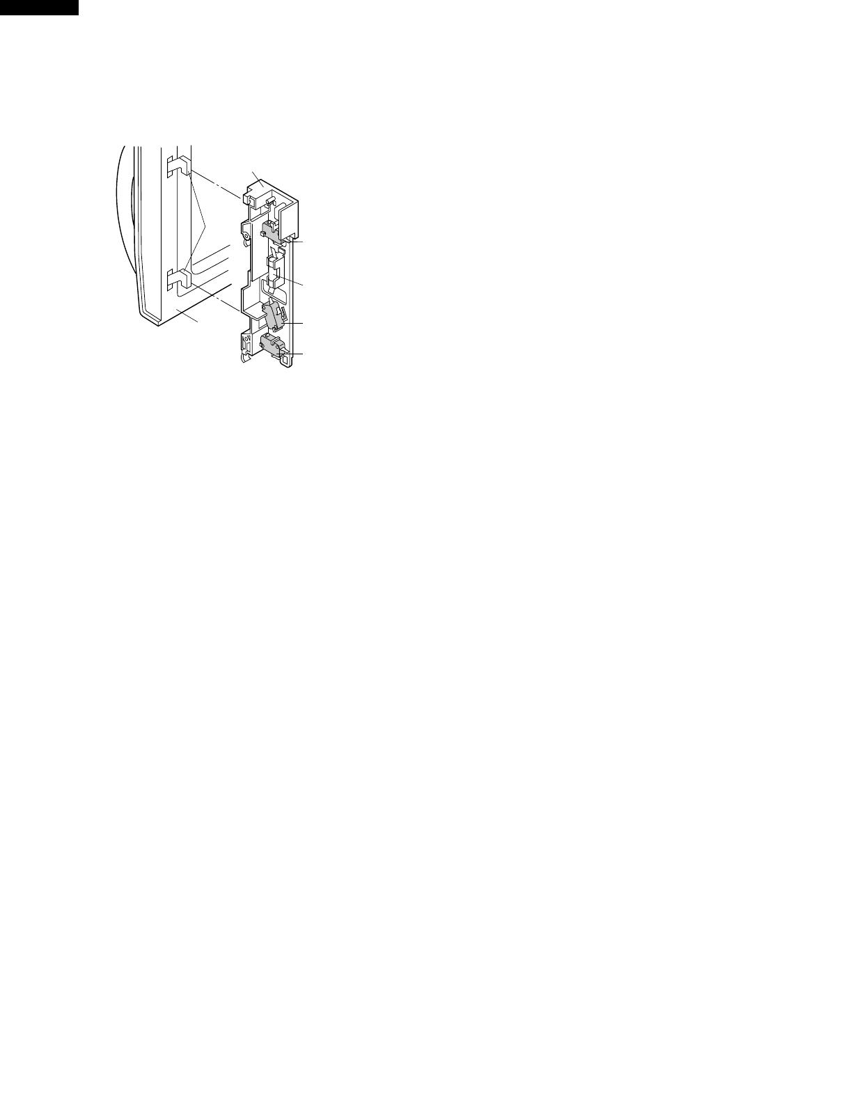
DOOR OPEN MECHANISM
The door is opened by pulling the door handle, refer to the
Figure D-1.
CAUTION: BEFORE REPLACING A BLOWN MONITOR
FUSE TEST THE DOOR SENSING SWITCH,
PRIMARY INTERLOCK RELAY (RY2), SEC-
ONDARY INTERLOCK SWITCH AND MONI-
TOR SWITCH FOR PROPER OPERATION.
(REFER TO CHAPTER "TEST PROCEDURE").
NOTE: MONITOR FUSE AND SWITCH ARE REPLACED
AS AN ASSEMBLY
TEMPERATURE FUSE (MG)
The temperature fuse located near the waveguide is
designed to prevent damage to the magnetron if an over
heated condition develops in the tube due to cooling fan
failure, obstructed air guide, dirty or blocked air intake, etc.
Under normal operation, the temperature fuse remains
closed. However, the temperature fuse will open at 302˚F
(150˚C) causing the oven to shut down.
THERMAL CUT-OUT (HOOD )
This thermal cut-out located on the right base plate. It is
designed to automatically turn on the hood fan motor
whenever the hot air rising from the conventional range
below causes the temperature at the thermal cut-out to rise
to 140˚F (60˚C) or higher, thus removing this hot air from
around microwave oven. When the temperature around the
thermal cut-out drops to 113˚F (45˚C) or lower, the thermal
cut-out shuts off the hood fan motor.
THERMAL CUT-OUT (CAVITY )
This thermal cut-out is located on the top of the oven cavity.
It is designed to prevent damage to the oven unit if the food
in the oven catches fire due to overheating produced by
improper setting of cooking time or failure of control unit.
Under normal operation, the thermal cut-out remains closed.
However, the thermal cut-out will open at 293˚F (145˚C)
causing the oven to shut down.
TURNTABLE MOTOR
The turntable motor rotates the turntable located on the
bottom of the oven cavity, so that the foods on the turntable
cook evenly during cooking. Turntable will turn in either
direction. The turntable motor can be turned off by touching
TURNTABLE ON/OFF pad.
COOLING FAN MOTOR
The cooling fan motor drives a blade which draws external
cool air. This cool air is directed through the air vanes
surrounding the magnetron and cools the magnetron. This air
is channelled through the oven cavity to remove steam and
vapors given off from the heating foods. It is then exhausted
through the exhausting air vents at the oven cavity.
HOOD
FAN MOTOR
The hood fan motor is a two-speed, single-phase, double
pole induction type, requiring a hood fan capacitor. It is
located outside the upper rear part of the oven cavity, is to
remove, from around the oven, hot air rising from the
conventional electric or gas range over which it is installed.
Figure D-1. Door Open Mechanism
DOOR SENSING AND SECONDARY INTERLOCK
SWITCHES
The secondary interlock switch is mounted in the lower
position of the latch hook and the door sensing switch in the
primary interlock system is mounted in the upper position of
the latch hook. They are activated by the latch heads on the
door. When the door is opened, the switches interrupt the
circuit to all components. A cook cycle cannot take place
until the door is firmly closed thereby activating both inter-
lock switches. The primary interlock system consists of the
door sensing switch and primary interlock relay located on
the control circuit board.
MONITOR SWITCH
The monitor switch is activated (the contacts opened) by the
latch head on the door while the door is closed. The switch
is intended to render the oven inoperative by means of
blowing the monitor fuse when the contacts of the primary
interlock relay (RY2) and secondary interlock switch fail to
open when the door is opened.
Functions:
1. When the door is opened, the monitor switch contact
close (to the ON condition) due to their being normally
closed. At this time the primary interlock relay (RY2) and
secondary interlock switch are in the OFF condition
(contacts open) due to their being normally open contact
switches. And the contacts of relay (RY1) are in the ON
condition (contacts close).
2. As the door goes to a closed position, the monitor switch
contacts are first opened and then the door sensing
switch and the secondary interlock switch contacts close.
(On opening the door, each of these switches operate
inversely.)
3. If the door is opened, and the primary interlock relay
(RY2) and secondary interlock switch contacts fail to
open, the monitor fuse blows simultaneously with closing
of the monitor switch contacts.
Secondary
Interlock
Switch
Monitor
Switch
Monitor
Fuse
Door
Sensing
Switch
Latch
Hook
Door
Latch
Heads
11
R-1600
R-1601
R-1602
TROUBLESHOOTING GUIDE
Never touch any part in the circuit with your hand or an uninsulated tool while the power supply is connected.
When troubleshooting the microwave oven, it is helpful to follow the Sequence of Operation in performing the checks. Many
of the possible causes of trouble will require that a specific test be performed. These tests are given a procedure letter which
will be found in the "Test Procedure "section.
IMPORTANT: If the oven becomes inoperative because of a blown monitor fuse, check the monitor switch, relay (RY1)
primary interlock relay (RY2), door sensing switch and secondary interlock switch before replacing the
monitor fuse. If monitor fuse is replaced, the monitor switch must also be replaced. Use part FFS-BA016/
KiT as an assembly.
IMPORTANT: Whenever troubleshooting is performed with the power supply cord disconnected. It may in, some cases,
be necessary to connect the power supply cord after the outer case has been removed, in this event,
1. Disconnect the power supply cord, and then remove outer case.
2. Open the door and block it open.
3. Discharge high voltage capacitor.
4. Disconnect the leads to the primary of the power transformer.
5. Ensure that the leads remain isolated from other components and oven chassis by using insulation tape.
6. After that procedure, reconnect the power supply cord.
When the testing is completed
1. Disconnect the power supply cord, and then remove outer case.
2. Open the door and block it open.
3. Discharge high voltage capacitor.
4. Reconnect the leads to the primary of the power transformer.
5. Reinstall the outer case (cabinet).
6. Reconnect the power supply cord after the outer case is installed.
7. Run the oven and check all functions.
This air is then expelled either vertically or horizontally
through the customer supplied duct system, or discharged
back into the kitchen.
STIRRER MOTOR
The stirrer motor drives the stirrer fan to stir the microwave
radiation from the waveguide.
HOOD LAMP
The hood lamps are mounted at the hood lamp angle on the
base cover. The hood lamps can be turned off and on by
touching the WORK LIGHT pad or the NIGHT LIGHT pad.
And also the brightness can be varied to high or low by
touching the WORK LIGHT pad or the NIGHT LIGHT pad.
12
R-1600
R-1601
R-1602
CK = Check / RE = Replace
POSSIBLE CASE AND 
DEFECTIVE PARTS
PROBLEM
TEST PROCEDURE
CONDITION
OFF
CONDITION
IDLE
CONDITION
MICROWAVE
COOKING
CONDITION
Home fuse blows when power cord is plugged into wall receptacle.
Monitor fuse blows when power cord is plugged into wall receptacle.
Display does not illuminate when power cord is first plugged into wall
receptacle.
Display does not operate properly when STOP/CLEAR key is touched.
(The time of day should appear on the display with beep sound during
normal condition.)
Oven lamp does not light with door is opened.
Hood fan motor operates when power cord is first plugged into wall
receptacle.
Temperature of oven base seems more than 140˚F (60˚C) because of
operation of the range below. But hood fan motor does not turn on
automatically. (Normally, food fan motor should be operating at low
speed.)
Hood lights do not turn on when WORK LIGHT pad or NIGHT LIGHT pad
is pressed.
Hood fan motor does not rotate at all with touched FAN HI/LO pad.
Speed of the hood fan motor does not change when the FAN HI/LO pad is
touched for this function.
Oven lamp does not light in cook cycle. (But it does light when door is
opened.)
Fan motor does not operate. (Oven lamp and turntable motor operate.)
Turntable motor does not operate (Oven lamp lights and fan motor
operate.)
Oven does not go into cook cycle when START pad is touched
Oven seems to be operating but little or no heat is produced in oven load.
(Food incompletely cooked or not cooked at all at end of cook cycle.)
Oven goes into a cook cycle but extremely uneven heating is produced in
oven load (food).
Variable cooking does not operate properly except Cooking Power 10 (P-
HI) mode.
Function of COMPU DEFROST does not operate properly.
Stirrer motor does not operate. (Other parts operate.)
Oven goes into COMPU DEFROST but food is not defrosted well.
CK LOW VOLTAGE
CK NO POWER AT OUTLET
RE SHORTED IN POWER CORD
CK OPENED OR SHORTED WIRING
CK HOOD MOTOR CAPACITOR
RE HOOD LAMP OR SOCKET
CK TURNTABLE OFF CONDITION
RE STIRRER MOTOR
RE TURNTABLE MOTOR
RE FAN MOTOR
RE OVEN LAMP OR SOCKET
P FOIL PATERN ON P.W.B.
O COMPU DEFROST
N RELAY (RY-5)
N RELAY (RY-4)
N RELAY (RY-3)
N RELAY (RY-2)
N RELAY (RY-1)
 M KEY UNIT
L CONTROL UNIT
K HOOD FAN MOTOR 
J HOOD HERMAL CUT-OUT 
I MONITOR FUSE 
H MONITOR SWITCH
G
PRIMARY INTERLOCK SYSTEM
F SECONDARY INTERLOCK SWITCH

E
TEMPERATURE FUSE OR THERMAL CUT-OUT
D HIGH VOLTAGE CAPACITOR
C H.V. RECTIFIER 
B POWER TRANSFORMER
A MAGNETRON
13
R-1600
R-1601
R-1602
B POWER TRANSFORMER TEST
TEST PROCEDURES
PROCEDURE
LETTER
COMPONENT TEST
1. Disconnect the power supply cord, and then remove outer case.
2. Open the door and block it open.
3. Discharge high voltage capacitor.
4. To test for an open filament, isolate the magnetron from the high voltage circuit. A continuity check
across the magnetron filament leads should indicate less than 1 ohm.
5. To test for a shorted magnetron, connect the ohmmeter leads between the magnetron filament leads
and chassis ground. This test should indicate an infinite resistance. If there is little or no resistance
the magnetron is grounded and must be replaced.
6. Reconnect all leads removed from components during testing.
7. Reinstall the outer case (cabinet).
8. Reconnect the power supply cord after the outer case is installed.
9. Run the oven and check all functions.
MICROWAVE OUTPUT POWER
The following test procedure should be carried out with the microwave oven in a fully assembled
condition (outer case fitted).
HIGH VOLTAGES ARE PRESENT DURING THE COOK CYCLE, SO EXTREME CAUTION SHOULD
BE OBSERVED.
Power output of the magnetron can be measured by performing a water temperature rise test. This test
should only be used if above tests do not indicate a faulty magnetron and there is no defect in the following
components or wiring: silicon rectifier, high voltage capacitor and power transformer. This test will require
a 16 ounce (453cc) measuring cup and an accurate mercury thermometer or thermocouple type
temperature tester. For accurate results, the following procedure must be followed carefully:
1. Fill the measuring cup with 16 oz. (453cc) of tap water and measure the temperature of the water with
a thermometer or thermocouple temperature tester. Stir the thermometer or thermocouple through
the water until the temperature stabilizes. Record the temperature of the water.
2. Place the cup of water in the oven. Operate oven at POWER 10(HIGH) selecting more than 60
seconds cook time. Allow the water to heat for 60 seconds, measuring with a stop watch, second hand
of a watch or the digital read-out countdown.
3. Remove the cup from the oven and again measure the temperature, making sure to stir the
thermometer or thermocouple through the water until the maximum temperature is recorded.
4. Subtract the cold water temperature from the hot water temperature. The normal result should be 29.2
to 54.2˚F(16.2 to 30.1˚C) rise in temperature. If the water temperatures are accurately measured and
tested for the required time period the test results will indicate if the magnetron tube has low power
output (low rise in water temperature) which would extend cooking time or high power output (high
rise in water temperature) which would reduce cooking time. Because cooking time can be adjusted
to compensate for power output, the magnetron tube assembly should be replaced only if the water
temperature rise test indicates a power output well beyond the normal limits. The test is only accurate
if the power supply line voltage is 120 volts and the oven cavity is clean.
A MAGNETRON ASSEMBLY TEST
1. Disconnect the power supply cord, and then remove outer case.
2. Open the door and block it open.
3. Discharge high voltage capacitor.
4. Disconnect the primary input terminals and measure the resistance of the transformer with an
ohmmeter. Check for continuity of the coils with an ohmmeter. On the R x 1 scale, the resistance of
the primary coil should be less than 1 ohm and the resistance of the high voltage coil should be
approximately 83.2 ohms; the resistance of the filament coil should be less than 1 ohm.
5. Reconnect all leads removed from components during testing.
6. Reinstall the outer case (cabinet).
7. Reconnect the power supply cord after the outer case is installed.
8. Run the oven and check all functions.
14
R-1600
R-1601
R-1602
TEST PROCEDURES
PROCEDURE
LETTER
COMPONENT TEST
1. Disconnect the power supply cord, and then remove outer case.
2. Open the door and block it open.
3. Discharge high voltage capacitor.
4. If the capacitor is open, no high voltage will be available to the magnetron. Disconnect input leads
and check for short or open between the terminals using an ohmmeter.
Checking with a high ohm scale, if the high voltage capacitor is normal, the meter will indicate
continuity for a short time and should indicate an open circuit once the capacitor is charged. If the
above is not the case, check the capacitor with an ohmmeter to see if it is shorted between either of
the terminals and case. If it is shorted, replace the capacitor.
5. Reconnect all leads removed from components during testing.
6. Reinstall the outer case (cabinet).
7. Reconnect the power supply cord after the outer case is installed.
8. Run the oven and check all functions.
D HIGH VOLTAGE CAPACITOR TEST
E CAVITY THERMAL CUT-OUT TEST
1. Disconnect the power supply cord, and then remove outer case.
2. Open the door and block it open.
3. Discharge high voltage capacitor.
4. A continuity check across the thermal cut-out terminals should indicate a closed circuit unless the
temperature of the thermal cut-out reaches approximately 293˚F(145˚C).
An open thermal cut-out indicates overheating of the oven, exchange the oven thermal cut-out and
check inside of oven cavity and for improper setting of cooking time or operation of control unit. Check
for restricted air flow through the vent holes of the oven cavity, especially the cooling fan and air guide.
5. Reconnect all leads removed from components during testing.
6. Reinstall the outer case (cabinet).
7. Reconnect the power supply cord after the outer case is installed.
8. Run the oven and check all functions.
MAGNETRON TEMPERATURE FUSE TEST
1. Disconnect the power supply cord, and then remove outer case.
2. Open the door and block it open.
3. Discharge high voltage capacitor.
4. A continuity check across the temperature fuse terminals should indicate a closed circuit. If the
temperature of the magnetron reaches approximately 302˚F(150˚C), the temperature fuse opens. An
open temperature fuse indicates overheating of the magnetron. Check for restricted air flow to the
magnetron, especially the cooling fan air guide.
5. Reconnect all leads removed from components during testing.
C HIGH VOLTAGE RECTIFIER TEST
1. Disconnect the power supply cord, and then remove outer case.
2. Open the door and block it open.
3. Discharge high voltage capacitor.
4. Isolate the rectifier from the circuit. Using the highest ohm scale of the meter, read the resistance
across the terminals and observe, reverse the leads to the rectifier terminals and observe meter
reading. If a short is indicated in both directions, or if an infinite resistance is read in both directions,
the rectifier is probably defective and should be replaced.
5. Reconnect all leads removed from components during testing.
6. Reinstall the outer case (cabinet).
7. Reconnect the power supply cord after the outer case is installed.
8. Run the oven and check all functions.
NOTE: Be sure to use an ohmmeter that will supply a forward bias voltage of more than 6.3 volts.
(HIGH VOLTAGES ARE PRESENT AT THE HIGH VOLTAGE TERMINAL, SO DO NOT ATTEMPT TO
MEASURE THE FILAMENT AND HIGH VOLTAGE.)
15
R-1600
R-1601
R-1602
TEST PROCEDURES
PROCEDURE
LETTER
COMPONENT TEST
1. Disconnect the power supply cord, and then remove outer case.
2. Open the door and block it open.
3. Discharge high voltage capacitor.
4. Before performing this test, make sure that the secondary interlock switch and the primary interlock
relay are operating properly, according to the above Switch Test Procedure. Disconnect the wire lead
from the monitor switch (COM) terminal. Check the monitor switch operation by using the ohmmeter
as follows. When the door is open, the meter should indicate a closed circuit. When the monitor switch
actuator is pushed by a screw driver through the lower latch hole on the front plate of the oven cavity
6. Reinstall the outer case (cabinet).
7. Reconnect the power supply cord after the outer case is installed.
8. Run the oven and check all functions.
CAUTION: IF THE THERMAL CUT-OUT OR TEMPERATURE FUSE INDICATES AN OPEN CIRCUIT
AT ROOM TEMPERATURE, REPLACE THERMAL CUT-OUT OR TEMPERATURE FUSE.
1. Disconnect the power supply cord, and then remove outer case.
2. Open the door and block it open.
3. Discharge high voltage capacitor.
4. Isolate the switch and connect the ohmmeter to the common (COM.) and normally open (NO) terminal
of the switch. The meter should indicate an open circuit with the door open and a closed circuit with
the door closed. If improper operation is indicated, replace the secondary interlock switch.
5. Reconnect all leads removed from components during testing.
6. Reinstall the outer case (cabinet).
7. Reconnect the power supply cord after the outer case is installed.
8. Run the oven and check all functions.
F SECONDARY INTERLOCK SWITCH TEST
H MONITOR SWITCH TEST
G PRIMARY INTERLOCK SYSTEM TEST
DOOR SENSING SWITCH
1. Disconnect the power supply cord, and then remove outer case.
2. Open the door and block it open.
3. Discharge high voltage capacitor.
4. Isolate the switch and connect the ohmmeter to the common (COM.) and normally open (NO) terminal
of the switch. The meter should indicate an open circuit with the door open and a closed circuit with
the door closed. If improper operation is indicated, replace the door sensing switch.
5. Reconnect all leads removed from components during testing.
6. Reinstall the outer case (cabinet).
7. Reconnect the power supply cord after the outer case is installed.
8. Run the oven and check all functions.
NOTE: If the door sensing switch contacts fail in the open position and the door is closed, the cooling
fan motor, stirrer motor and oven light will be activated by RY1.
PRIMARY INTERLOCK RELAY (RY2)
1. Disconnect the power supply cord, and then remove outer case.
2. Open the door and block it open.
3. Discharge high voltage capacitor.
4. Disconnect two (2) wire leads from the male tab terminals of the Primary Interlock Relay. Check the
state of the relay contacts using a ohmmeter. The relay contacts should be open. If the relay contacts
are closed, replace the circuit board entirely or the relay itself.
5. Reconnect all leads removed from components during testing.
6. Reinstall the outer case (cabinet).
7. Reconnect the power supply cord after the outer case is installed.
8. Run the oven and check all functions.
16
R-1600
R-1601
R-1602
I BLOWN MONITOR FUSE TEST
TEST PROCEDURES
PROCEDURE
LETTER
COMPONENT TEST
1. Disconnect the power supply cord, and then remove outer case.
2. Open the door and block it open.
3. Discharge high voltage capacitor.
4. If the monitor fuse is blown when the door is opened, check the primary interlock relay, secondary
interlock switch and monitor switch according to the "TEST PROCEDURE" for those switches before
replacing the blown monitor fuse.
CAUTION: BEFORE REPLACING A BLOWN MONITOR FUSE, TEST THE PRIMARY INTERLOCK
RELAY, SECONDARY INTERLOCK SWITCH, DOOR SENSING SWITCH AND MONITOR
SWITCH FOR PROPER OPERATION.
If the monitor fuse is blown by improper switch operation, the monitor fuse and monitor switch must
be replaced with "monitor fuse and monitor switch assembly" part number FFS-BA016/KiT, even if
the monitor switch operates normally. The monitor fuse and monitor switch assembly is comprised
of a 20 ampere fuse and switch.
5. Reconnect all leads removed from components during testing.
6. Re-install the outer case (cabinet).
7. Reconnect the power supply cord after the outer case is installed.
8. Run the oven and check all functions.
with the door opened (in this condition the plunger of the monitor switch is pushed in), the meter should
indicate an open circuit. If improper operation is indicated, the switch may be defective. After testing
the monitor switch, reconnect the wire lead to the monitor switch (COM) terminal and check the
continuity of the monitor circuit.
5. Reconnect all leads removed from components during testing.
6. Reinstall the outer case (cabinet).
7. Reconnect the power supply cord after
the outer case is installed.
8. Run the oven and check all functions.
Secondary
Interlock
Switch
Monitor
Switch
Screw Driver
Ohmmeter
Black
White
/White
J HOOD THERMAL CUT-OUT TEST
1. Disconnect the power supply cord, and then remove outer case.
2. Open the door and block it open.
3. Discharge high voltage capacitor.
4. A continuity check across the thermal cut-out terminals should indicate an open circuit unless the
temperature of the thermal cut-out reaches approximately 140˚F(60˚C) or more. At that temperature,
the contacts will close. The thermal cut-out opens automatically at approximately 113˚F(45˚C).
5. Reconnect all leads removed from components during testing.
6. Reinstall the outer case (cabinet).
7. Reconnect the power supply cord after the outer case is installed.
8. Run the oven and check all functions.
K HOOD FAN MOTOR TEST
1. Disconnect the power supply cord, and then remove outer case.
2. Open the door and block it open.
3. Discharge high voltage capacitor.
4. If the motor does not turn, touch the FAN HI / LO pad once (set hood fan motor power "HIGH") and
check voltage between pins "1" and "2" (Blue and Black wires) of the 6 pin connector. If 120 Volts
appear and the hood capacitor is good, replace the hood fan assembly. If 120 Volts does not appear,
check the motor circuit. The resistance values of motor terminals are as follows:
17
R-1600
R-1601
R-1602
TEST PROCEDURES
PROCEDURE
LETTER
COMPONENT TEST
Resistance between;
BLU (1) AND YLW (4) = 0 (Shorted)
BLK (2) AND YLW (4) = 32
BLU (1) AND BLK (2) = 32
BLK (2) AND WHT (3) = 20
WHT (3) AND RED (5) = 45
123
45
BLU BLK WHT
YLW RED
6-PIN CONNECTOR
OF HOOD FAN MOTOR
5. Reconnect all leads removed from components during testing.
6. Reinstall the outer case (cabinet).
7. Reconnect the power supply cord after the outer case is installed.
8. Run the oven and check all functions.
L TOUCH CONTROL PANEL ASSEMBLY TEST
The touch control panel consists of circuits including semiconductors such as LSI, ICs, etc. Therefore,
unlike conventional microwave ovens, proper maintenance cannot be performed with only a voltmeter
and ohmmeter.
In this service manual, the touch control panel assembly is divided into two units, Control Unit and Key
Unit, and also the Control Unit is divided into two units, LSI Unit and Power Unit, and troubleshooting by
unit replacement is described according to the symptoms indicated.
Before testing,
1) Disconnect the power supply cord, and then remove outer case. Refer to procedure of "HOOD
EXHAUST LOUVER REMOVAL", "REMOVAL OF OVEN FROM WALL" and "OUTER CASE
REMOVAL".
2) Open the door and block it open.
3) Discharge high voltage capacitor.
4) Disconnect the leads to the primary of the power transformer.
5) Ensure that these leads remain isolated from other components and oven chassis by using
insulation tape.
6) After that procedure, re-connect the power supply cord.
1. Key Unit.
NOTE ;
1) Disconnect the power supply cord, and then remove outer case.
2) Open the door and block it open.
3) Discharge high voltage capacitor.
4) Check key unit ribbon connection before replacement.
5) Reconnect all leads removed from components during testing.
6) Re-install the outer case (cabinet).
7) Reconnect the power supply cord after the outer case is installed.
8) Run the oven and check all functions.
The following symptoms indicate a defective key unit.
a) When touching the pads, a certain pad produces no signal at all.
b) When touching a number pad, two figures or more are displayed.
c) When touching the pads, sometimes a pad produces no signal.
If the key unit is defective.
1) Disconnect the power supply cord, and then remove outer case.
2) Open the door and block it open.
3) Discharge high voltage capacitor.
4) Replace the key unit.
5) Reconnect all leads removed from components during testing.
32
20 45
HOOD FAN
CAPACITOR
YLW
RED
BLU
BLK
1
2
3
WHT
4
5
18
R-1600
R-1601
R-1602
TEST PROCEDURES
PROCEDURE
LETTER
COMPONENT TEST
6) Re-install the outer case (cabinet).
7) Reconnect the power supply cord after the outer case is installed.
8) Run the oven and check all functions.
2. Control Unit.
The following symptoms indicate a defective control unit. Before replacing the control unit, perform
the Key unit test (Procedure M) to determine if control unit is faulty.
2-1 In connection with pads.
a) When touching the pads, a certain group of pads do not produce a signal.
b) When touching the pads, no pads produce a signal.
2-2 In connection with indicators
a) At a certain digit, all or some segments do not light up.
b) At a certain digit, brightness is low.
c) Only one indicator does not light.
d) The corresponding segments of all digits do not light up; or they continue to light up.
e) Wrong figure appears.
f) A certain group of indicators do not light up.
g) The figure of all digits flicker.
2-3 Other possible problems caused by defective control unit.
a) Buzzer does not sound or continues to sound.
b) Clock does not operate properly.
c) Cooking is not possible.
When testing is completed,
1) Disconnect the power supply cord, and then remove outer case.
2) Open the door and block it open.
3) Discharge high voltage capacitor.
4) Reconnect all leads removed from components during testing.
5) Re-install the outer case (cabinet).
6) Reconnect the power supply cord after the outer case is installed.
7) Run the oven and check all functions.
1. Disconnect the power supply cord, and then remove outer case.
2. Open the door and block it open.
3. Discharge high voltage capacitor.
4. If the display fails to clear when the STOP/CLEAR pad is depressed, first verify the flat ribbon cable
is making good contact, verify that the door sensing switch (stop switch) operates properly; that is the
contacts are closed when the door is closed and open when the door is open. If the door sensing
switch (stop switch) is good, disconnect the flat ribbon cable that connects the key unit to the control
unit and make sure the door sensing switch is closed (either close the door or short the door sensing
switch connecter). Use the Key unit matrix indicated on the control panel schematic and place a
jumper wire between the pins that correspond to the STOP/CLEAR pad making momentary contact.
If the control unit responds by clearing with a beep the key unit is faulty and must be replaced. If the
control unit does not respond, it is faulty and must be replaced. If a specific pad does not respond,
the above method may be used (after clearing the control unit) to determine if the control unit or key
pad is at fault.
5. Reconnect all leads removed from
components during testing.
6. Re-install the outer case (cabinet).
7. Reconnect the power supply cord
after the outer case is installed.
8. Run the oven and check all functions.
M KEY UNIT TEST
G 8
5
0
4
9
3
8
2
7
1
6
G 7
COMPU
DEFROST
NIGHT
LIGHT
STOP
CLEAR
MEMORY
COOK
WORK
LIGHT
POWER
LEVEL
MINUTE
PLUS
POPCORN
FAN
HI / LO
TURNTABLE
ON / OFF
CUSTOM
HELP
DINNER LUNCH
BREAKFAST
G 6 G 5 G 4 G 3 G 2 G 1
G14 G13 G12 G11 G10 G 9
CLOCK
TIMER
START
TOUCH ON
  • Page 1 1
  • Page 2 2
  • Page 3 3
  • Page 4 4
  • Page 5 5
  • Page 6 6
  • Page 7 7
  • Page 8 8
  • Page 9 9
  • Page 10 10
  • Page 11 11
  • Page 12 12
  • Page 13 13
  • Page 14 14
  • Page 15 15
  • Page 16 16
  • Page 17 17
  • Page 18 18
  • Page 19 19
  • Page 20 20
  • Page 21 21
  • Page 22 22
  • Page 23 23
  • Page 24 24
  • Page 25 25
  • Page 26 26
  • Page 27 27
  • Page 28 28
  • Page 29 29
  • Page 30 30
  • Page 31 31
  • Page 32 32
  • Page 33 33
  • Page 34 34
  • Page 35 35
  • Page 36 36
  • Page 37 37
  • Page 38 38
  • Page 39 39
  • Page 40 40
  • Page 41 41
  • Page 42 42
  • Page 43 43
  • Page 44 44
  • Page 45 45
  • Page 46 46
  • Page 47 47
  • Page 48 48

Dual MS6130 User manual

Category
Microwaves
Type
User manual
This manual is also suitable for

Ask a question and I''ll find the answer in the document

Finding information in a document is now easier with AI