Page is loading ...

MODELS
AT8500
AT8700
B LENDING H IGH F IDELITY AND A RCHITECTURE
®
INSTALLATION & OPERATION GUIDE
MODELS
AT8500
AT8700
ADVANCED
TECHNOLOGY
®
IN-WALL LOUDSPEAKERS
DS00222A/AT8500-8700 3/1/99 10:47 AM Page 2

Congratulations!
Thank you for choosing Advanced Technology In-Wall Loudspeakers from Niles.
With proper installation and operation, you'll enjoy years of trouble-free use.
Niles manufactures the industry's most complete line of custom installation
components and accessories for audio/video systems. For a free full line catalog
write: Niles, Catalog Request, P. O. Box 160818, Miami, Florida 33116-0818
©1999 Niles Audio Corporation. Because Niles strives to continuously improve its products, Niles reserves the right to
change product specifications without notice. Niles, the Niles logo and Blending High Fidelity and Architecture are regis-
tered trademarks of Niles Audio Corporation. BumpBack, X-Matrix, DSFG, LinearTrack and MicroSensor are trademarks of
Niles Audio Corporation. Dynamat is a trademark of Dynamic Control Dolby is a registered trademark of Dolby Laboratories
Licensing Corporation. Decora is a registered trademark of Leviton Manufacturing Co.
TABLE OF CONTENTS
INTRODUCTION 1
FEATURES AND BENEFITS 1
INSTALLATION CONSIDERATIONS 3
SPEAKER PLACEMENT 5
INSTALLATION FUNDAMENTALS 10
INSTALLATION OF BRACKETS, FRAMES AND GRILLES IN NEW CONSTRUCTION 14
INSTALLATION OF BRACKETS, FRAMES AND GRILLES IN EXISTING WALLS 16
INSTALLATION OFTHE SPEAKER AND GRILLE IN NEWOR EXISTING CONSTRUCTION 17
OPERATION 20
SPECIFICATIONS 21
WARRANTY REGISTRATION CARD 24
LIMITED WARRANTY 25
DS00222A/AT8500-8700 3/1/99 10:47 AM Page 3

Introduction
The AT or Advanced Technology group of
In-Wall Loudspeakers are designed to
deliver truly stunning performance with
optimum installation flexibility. All models
in the AT series are constructed using the
highest quality components and utilize
advanced materials technology to create
speakers capable of reproducing both
music and movie soundtracks with stun-
ning realism and sonic impact. They are
perfect anywhere that quality of sound is
the most important consideration.
An AT8500/AT8700 Series Speaker Kit;
AT8000 Series Bracket Kit; and an
AT8000 Series Frame/Grille Kit are
required to install one pair of AT8500,
AT8700 In-Wall Loudspeakers in either
new or existing construction.
Features and Benefits
Patent Pending Dispersion Control
Array with Directed Sound Field
Geometry
™ (DSFG)
Both the AT8500 and AT8700 models
employ Niles’ Directed Sound Field
Geometry (DSFG). With DSFG, the tweeter
is offset from the center of the dual
midrange drivers. The resulting acoustic
interaction between the dual midrange dri-
vers and the offset tweeter directs the flattest
frequency and phase response approxi-
mately 15 degrees off-axis from the tweeter.
By mounting this innovative midrange/
tweeter design on 360 degree rotating and
30 degree swiveling low diffraction
Dispersion Control Array, the AT8500 and
AT8700 models can deliver pinpoint imag-
ing and optimum phase and frequency
response regardless of speaker placement or
listening position.
High Performance Woofer and
Tweeter Designs
Both the AT8500 and AT8700 models
incorporate woofer designs which feature
cast aluminum frames, vented pole pieces,
custom debris screens, inverted dust caps,
butyl rubber surrounds, and Niles
BumpBack™ magnet structure to provide
powerful and accurate bass response.
Additionally, the AT8700 features a bi-filer
voice coil winding which enhances the
speaker’s already flat frequency response
characteristics, lowers distortion, and
increases the woofer’s efficiency.
AT8500—Aluminum/Urethane
Composite Woofer
The AT8500’s 8” woofer is constructed of a
composite of aluminum and urethane
which is extremely light, highly efficient,
and offers superior damping characteristics.
Dual Hyperbolic Aluminum/Urethane
Dome Midranges and Tweeter
The AT8500’s dual 1-1/2” midrange drivers
and single 1” tweeter incorporate the same
aluminum/urethane composite used in the
construction of the AT8500’s woofer. The
result is a very natural sounding speaker
capable of reproducing mids and highs
with superb detail and accuracy.
AT8700—Aluminum/Titanium/Urethane
Composite Woofer
The AT8700’s 8” woofer is constructed of a
three layer composite of aluminum, titani-
um, and urethane to offer unparalleled
rigidity, excellent transient response, and
very low distortion.
Dual Hyperbolic Dome Midranges
and Tweeter
The AT8700’s dual 1-1/2” midrange drivers
and single 1” tweeter all share composite
design consisting of an inner aluminum
layer that forms the dome, a stiffening layer
of titanium, and a damping layer of ure-
thane to kill unwanted resonances.
Features and Benefits
1
Patent Pending
DS00222A/AT8500-8700 3/1/99 10:48 AM Page 27

Computer Optimized Crossover with
Acoustical Configuration Controls
The second order Linkwitz-Riley crossover
is computer optimized and constructed of
premium components for unparalleled
sonic performance. The baffle-mounted
Tone Controls provide installers with Bass,
Midrange and Treble adjustment in four
increments (-2dB, Flat, +2dB, +4dB).
Additionally, the AT8700 features a Sub-
Bass Boost control which adds 3dB at 60Hz
to enhance the speaker’s low frequency
performance if desired, and two Linear
Track™ Filters. These controls can be used
to fine tune the speakers performance or to
compensate for less than ideal room
acoustics. (For more information, see
Setting the Tone Controls on page 20).
BumpBack™ Woofer Magnet
Niles engineers have utilized a unique mag-
net construction allowing far greater “throw”
or voice coil excursion. This enables Niles
AT loudspeakers to play louder without
mechanical distortion or “bottoming”.
6mm Polycarbonate X-Matrix™
Reinforced Baffle
The AT8500 and AT8700 models feature an
extra thick (6mm) polycarbonate, X-Matrix
baffle design which uses specially molded
ribs to add rigidity to the baffle assembly.
The end result is better bass and improved
midrange detail.
Weather Resistant Construction
The AT8500 and AT8700 loudspeakers fea-
ture drivers which are impervious to mois-
ture; the grille (sold separately as part of the
AT8000 Series Frame and Grille kit) is
made of aluminum, and all exposed hard-
ware is constructed of stainless steel.
Absolutely Flush to the Wall
Appearance
The unique mounting system of the AT loud-
speakers securely clamps the frame to the
bracket, sandwiching the wall material
between them. Because the clamping action
is totally uniform around the frame, there are
no shadows or gaps between the wall and the
frame. Additionally, the Niles mounting sys-
tem is carefully optimized to stiffen the sur-
rounding drywall and prevent it from resonat-
ing. You hear only the music, not the drywall.
Easy Retrofit Installation in your
Existing Home
Designed for ease of installation, the Niles
mounting system makes retrofit installa-
tions simple and fast. A supplied template
assures fast and accurate hole cutting. The
bracket slips behind the drywall and the
screws secure the bracket to the frame,
sandwiching the drywall between them.
The speaker baffle attaches to the frame,
and the grille mounts over the speaker.
Three Stage Installation System for
Remodels or New Construction
You install only the parts you need for a par-
ticular stage of construction. When the fram-
ing and wiring are finished, you install the
bracket. After the drywall is up, but before
the painter begins to paint, you install the
frame and provide the painter with the alu-
minum grilles so that they can be painted to
match the surroundings. Only when con-
struction is completely finished do you put
the valuable speaker in the wall. You don’t
have to mask or prep the speaker for paint-
ing, and worries about theft during the final
phases of construction are never an issue!
Eight Ohm Impedance
The AT8500 and AT8700 speakers are
designed to be compatible with most ampli-
fiers. Their eight ohm impedance is an easy
electrical load for most amplifiers to drive.
Low Diffraction, Paintable
Aluminum Grilles
AT speakers are available with aluminum
grilles. The powder-coated aluminum grille
has hundreds of precisely sized perforations,
creating an acoustically transparent grille.
Infrared Sensor Mount
The speaker baffle has a locator designed for
the Niles MS-1 MicroSensor,™ a miniature
infrared sensor. The MS-1 installs discretely
behind the aluminum grille and therefore
minimizes wall clutter in your home. When
you want to control your equipment, you
simply point your remote control at the
speaker from up to 15 feet away.
Features and Benefits
2
DS00222A/AT8500-8700 3/1/99 10:47 AM Page 4

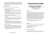
New Construction Wings
Bracket
Frame
Speaker Baffle
Grille
Recommended Amplifier Power
For satisfactory performance, we recom-
mend an amplifier with a power rating of
twenty to two hundred watts for the
AT8500 and AT8700 speakers. Curiously,
most speakers are not damaged by large
amplifiers but by small amplifiers. If your
system is playing loudly, a small amplifier
will run out of power very quickly. When
an amplifier runs out of power it creates
damaging “clipping” distortion. A large
amplifier will play at the same volume
without distorting. (For more information
about clipping distortion, see the section
on Operation, on page 20).
Incorporating a Local Volume Control
In a multi-room system there is one indis-
pensible control for true convenience—a
local volume control. It allows you to
adjust the volume of the speakers without
leaving the room.
Plan to wire the system so that each pair of
speakers has its own volume control built
into the wall (think of a volume control as
a dimmer switch for sound).
Niles makes a wide range of high perfor-
mance indoor and outdoor volume con-
trols. They are available in Standard or
Decora
®
style faceplates (just like your light
switches and dimmers). Volume controls
Installation Considerations
3
Figure 1
Model AT8700 Shown
Installation Considerations
DS00222A/AT8500-8700 3/1/99 10:48 AM Page 25

are connected in line with the speaker, so
you must connect the wire from the ampli-
fier to the volume control and then from
the volume control to the speaker.
Speaker Wire
Use 2-conductor speaker wire when con-
necting AT speakers to your receiver or
amplifier. For most applications, we recom-
mend you use a minimum of 16 or 18 gauge
wire. For wiring runs longer than 80 feet we
recommend a minimum of 14 gauge wire.
The gold plated binding post terminals of
the AT speakers will accommodate up to 8
gauge wire directly. Banana jack or pin
connectors may also be used.
When wire is to be run inside walls, spe-
cial jacketing (CL-2 or CL-3) is required to
both protect the wire and for fire preven-
tion. In some areas conduit is required. For
a trouble-free installation, low voltage
wire such as speaker wire must be run in
accordance with the National Electrical
Code and any applicable provisions of the
local building code. If you are unsure of
the correct installation techniques, wire
jacket or type of conduit to use, consult a
professional audio/video installer, your
building contractor, or the local building
and inspection department.
Incorporating a Remote Control
If you are planning to use a stereo system
with a hand held IR remote control, con-
sider the advantages of installing a Niles IR
Repeater System. You are able to control all
of the functions of your system from the
room with the remote pair of speakers.
Niles makes a number of IR sensors which
install in the wall, in the ceiling, in cabi-
netry, on tabletops, or even behind the
grille of your Niles AT speakers.
An IR sensor requires that a 2-conductor
shielded wire (West Penn D291 or equiva-
lent) be home run from each sensor loca-
tion to the main equipment location. This
wire is normally run beside the speaker
wire at the same time. Typically, the sensor
is placed in a location that faces your lis-
tening position. Most remote controls will
have an effective line of sight range of 18
to 30 feet with any Niles sensor placed in
a wall, ceiling, on a cabinet or tabletop.
However, when you place a Niles MS-1
MicroSensor behind the perforated alu-
minum grille of a speaker, the sensor’s
effective range is reduced to 9 to 15 feet.
Acoustical Treatment Options
For the best performance from your AT
speakers, acoustically treating the sur-
rounding drywall is suggested. In new con-
struction installations, the most practical
option is to block off the wall cavity both
above and below the area where the
speaker will be installed. This will create a
“backbox” containing a specific volume of
air in which the performance of the
AT8500 and AT8700 speakers will be opti-
mized. When installing the AT speakers in
a standard wall (16” stud spacing with 2x4
studs) the suggested air volume would be
2540 cubic inches or 52” of space
between the top and bottom walls of the
“backbox”. If the speakers are to be
installed in a 2x6 wall, a true backbox may
be constructed using 1/2” or 5/8” thick
Medium Density Fiberboard (MDF). The
dimensions of the enclosure may be varied
in terms of height, width, and depth, as
long as the interior volume of the enclosure
remains approximately 2540 cubic inches.
Although the AT speakers utilize an infinite
baffle design which does not require the
use of a backbox, critical listeners may
Installation Considerations
TECH TIP
Wire size is expressed by its AWG (American Wire
Gauge) number. The lower the number, the larger
the wire, i.e. twelve AWG is physically larger than
fourteen AWG.
4
DS00222A/AT8500-8700 3/1/99 10:47 AM Page 6

appreciate the tighter bass and extended
frequency response into the lower octaves
that the use of a backbox (or blocking off
the wall cavity) will provide. Ahole cutting
template is provided with the AT8000
Series Bracket Kit. The cutout for the speak-
er must measure 9-3/4” x 17-1/4”.
Insulating the Wall Cavity
When it is not possible to use a backbox,
good results can be achieved by treating
the interior of the drywall cavity with
Dynamat™ or a similar cabinet damping
material. At least two linear feet of damp-
ing material should be adhered to the rear
wall and to the front wall (one foot above
and one foot below the cutout) of the wall
cavity. Additionally, insulating the wall
cavity behind the speaker with fiberglass
insulation (e.g., R-19 unbatted insulation)
will improve performance. Try to keep the
amount of insulation used for each speak-
er equal, as bass output will be more con-
sistent. Further improvement can be made
by wedging a brace of 1x1 stock between
the front and rear walls, both above and
below the cutout. Use care when inserting
the brace, as too much pressure will create
a bulge in the wall.
Speaker Placement
The AT8500 and AT8700 speakers feature
a low diffraction midrange/tweeter array
which employs Niles’ DSFG. This innova-
tive driver configuration can be adjusted to
provide optimum phase and frequency
response at the listening position. Please
read
Positioning the Midrange/Tweeter
Array
under Installation of the Speaker
and Grille in New or Existing Construction
on page 17 before deciding on a final
installation location for your AT8500 or
AT8700 speakers.
Placement for Critical Listening
If you like to imagine that the band or
orchestra is playing in front of you as you lis-
ten to music, or you are very conscious of
Speaker Placement
5
Speaker
Placement
Zone
Speaker
Placement
Zone
10’
5’
10’
Figure 2
DS00222A/AT8500-8700 3/1/99 10:48 AM Page 23

clarity, detail and the textures of the individ-
ual instruments, you are a critical listener. In
a home theater, the intelligibility of dialog
and action reproduced by the front speakers
is paramount! The position of the speakers
plays a very important role in how clear the
sound is and how a stereo image is created.
Here are some guidelines to make the
process of placement quick and easy.
Make sure the sound will not be blocked or
reflected off of furniture or other objects.
You should have a direct line of sight with
the front of the speaker. To determine the
best position, measure the “listening” dis-
tance between the ideal listening position
(your favorite chair or couch) and the wall
in which you plan to install the speakers.
Try to place the speakers so that they are
equally distant from your listening spot and
at least one half of the listening distance
apart (this maintains a large pleasant stereo
“image”). In home theater applications
where there is a center channel you may
choose to space the left and right main
speakers farther apart for a “bigger than
life” sound with Dolby
®
encoded movies
and TV shows. However, for combined
music and movie usage stay within the
good placement zone for music. For exam-
ple; if you are ten feet back from the wall,
the speakers should be between five and
ten feet apart (See Figure 2).
The Boundary Effect
Corners can affect the bass response of the
speaker powerfully! This is called the
boundary effect. You will emphasize partic-
ular bass frequencies and cancel out other
bass frequencies when you place speakers
close to the wall/ceiling boundary or a cor-
ner wall boundary. This can make the
speaker sound excessively boomy and inac-
curate to some listeners, while to others it
just seems like more bass sound. A good
rule of thumb is if you always listen to your
current pair of speakers with the bass turned
up, you’ll enjoy corner placement. If you
keep your preamp or receiver’s tone con-
trols at neutral, try to keep the speakers at
least one or two feet from the boundaries of
the room. The baffle-mounted Acoustical
Configuration Controls may be used to help
reduce the affect of corner placement (or the
room’s own acoustics) on the speakers per-
formance. (For more information, see
Setting the Tone Controls on page 20).
Placement for Varying Listening
Positions
If you want the freedom to sit anywhere in a
room facing any direction, and/or find that
you prefer the “all around you” sound of
some car stereos to a conventional “sound
stage” facing you, consider the speaker
placement techniques professional installers
use in restaurants and bars. They place
Speaker Placement
AT8700
AT8700
AT8700
TV
Not Greater
than 24"
Figure 3
For an AT8700 placed above a
TV, install the speaker with the
tweeter up.
6
DS00222A/AT8500-8700 3/1/99 10:47 AM Page 8

speakers in an array around the listening
area, so that the music is always surround-
ing you, regardless of the direction you face.
The rule of thumb is to add one pair of
speakers for every 100 to 200 square feet of
listening area. Curiously, this is not so that
you can play the music louder, but so that
you can play it softer! When you have only
one pair of speakers in a large room you will
notice that when the sound is perfect in one
part of the room, it is too loud near the
speakers. By placing more than one pair in
the room you will avoid these “hot spots” of
loud sound and create more sonic
ambiance while maintaining clarity and rich
sound everywhere.
You can make listener position even less
critical by using mono rather than stereo.
This can be difficult to achieve with normal
stereo amplifiers. However, Niles manu-
factures Systems Integration Amplifiers
which enable one room to be wired in
stereo while other rooms are wired in
mono! Consult your local Niles dealer for
more information.
In smaller rooms or rooms that are infre-
quently used, you typically can’t justify the
expense of more than two speakers. Try to
bracket the room with the two speakers.
Diagonal placement is a very effective way
to stretch the coverage pattern of two
speakers. You can also compromise
between direct sound (for detail and clari-
ty) and reflected sound (the ambient or “all
around you” effect). By trying to place the
speakers so that they create as much
reflected sound as possible, you emphasize
the ambient effect. They can be up high in
Speaker Placement
7
Perforated Screen
AT8700
AT8700
AT8700 AT8700
Figure 4
For an AT8500 or AT8700 speaker placed below a projection screen, position the Midrange/Tweeter Array
horizontally with the tweeter facing down. For an AT speaker installed behind a perforated screen, the
Array should be positioned horizontally with the tweeter facing up if above ear level, or facing down if
below ear level. The speaker itself may be installed either horizontally or vertically.
DS00222A/AT8500-8700 3/1/99 10:48 AM Page 21

the wall or even down low at power outlet
height, in the ceiling, near corners, or
directed at reflective objects and walls. The
more reflected sound there is in the room
the stronger the ambient effect at low vol-
umes. You should use moderation, howev-
er, otherwise the compromise becomes too
one sided and at high volumes the sound
will be blurred and less distinct.
Placement for Rear Home Theater
Applications
In a home theater, the goal is to reproduce
the experience of a great movie theater in
our homes. The biggest difference between
the two is the rear or surround speaker array.
In a commercial theater, it is not uncommon
to see twenty or thirty speakers around the
audience. This huge array of speakers
assures that you will feel completely sur-
rounded by the ambient soundtrack of the
movie. Film makers try to use the “surround”
soundtrack to envelope you in the environ-
ment on screen. They will place background
music, rain sounds, traffic noise, etc. on the
“surround” soundtrack. In a home with a
single pair of speakers it is easy for the jungle
sounds to sound like they are “in the middle
of your head” just like headphones!
A single pair of AT Loudspeakers, properly
placed, can create a very convincing simu-
Speaker Placement
8
Figure 6
If the primary listening position is towards the center of the room as depicted in figure 6, place the rear
speakers high up on the rear wall or in the ceiling as pictured.
Figure 5
If the primary listening position is towards the back of the room as depicted in figure 5, place the rear
speakers high up on the side wall or in the ceiling with the array closest to the ceiling as pictured.
DS00222A/AT8500-8700 3/1/99 10:47 AM Page 10

lation of an array of speakers. If you place
them near a hard reflecting surface you can
make one pair of speakers sound like sever-
al. Create as many reflections as possible by
mounting the speakers up high in the wall
and aim the Midrange/Tweeter Array into
the corners or at an adjoining wall or ceiling
to diffuse the sound (See Figures 5, 6 and 7).
Mounting the speakers as far away as you
can from the listening area will also create
additional reflections. However, all of these
placement techniques require that you work
your surround sound amplifier channels
harder. If the surround sound system you are
using has a small five or ten watt amplifier
for the rear speakers, stay within five to eight
feet of the listening location. If you are using
a 25 to 50 watt amplifier you can mount the
speakers 10 to 15 feet away from the listen-
ing location and still achieve reasonably
high volume levels.
Of course, the best way to emulate the
sound of multiple speakers is to use multiple
speakers. In large or unusually shaped
rooms this might be the only way to achieve
a good effect. If you like to listen to music
surround modes which emulate concert hall
acoustics, more than two surround speakers
will prove extraordinarily effective. With
Niles AT loudspeakers it is easy to add
another pair without affecting the decor of
the room. However, you will need to use a
much more powerful amplifier than that
which is built into a typical surround sound
receiver or amplifier. Niles makes a number
of Systems Integration Amplifiers with pro-
prietary features that make them uniquely
suited to enhance a good surround sound
system. Consult your Niles dealer for more
information (See Figure 7).
Speaker Placement
9
Figure 7
If you use multiple rear speakers or have an irregularly shaped listening area as shown in figure 7,
place the speakers high up on the rear and side walls or in the ceiling as pictured.
DS00222A/AT8500-8700 3/1/99 10:48 AM Page 19

Installation
Fundamentals
Running the Speaker Wire in New
Construction
If you have doubts about whether you are
capable of installing Niles AT Series speak-
ers in your walls, consult a Niles dealer or
professional installer. They have special
tools, techniques, and experience to make
the impossible possible. The installer can
provide you with an estimate before any
work is done.
Scheduling and Pr
eparation
Plan to schedule the speaker wiring after
the electrical wiring is finished. That way
you can avoid wire routes which could
potentially induce hum over the speaker
wire. The basic rules are:
• Never run speaker wire through the
same hole as an electrical cable.
• Never run speaker wire into the same
J-box as electrical cable.
• Avoid running the speaker wire beside
the electrical cable. Keep it at least three
or four feet distant from any electrical
power cable.
Side-by-side wiring is unavoidable in partic-
ular spots in every house, just move the
speaker wire route away as soon as possi-
ble. If construction forces a side by side run
for more than ten feet, install metal conduit
or shielded speaker wire. Low-voltage wires
such as doorbells, intercoms, telephone,
security, or television cannot cause interfer-
ence or hum on your speaker wires, so you
can safely run all of them at the same time,
through the same holes, side-by-side.
Before you drill any holes, mount the
speaker brackets in the desired speaker
locations and mount p-rings or open
backed J-boxes where the in-wall volume
controls and stereo equipment will be.
Safety First!
Wear gloves, safety goggles and head pro-
tection when drilling. Avoid nails, they ruin
bits and they can create injury. Pay partic-
ular care when using “hole-hogs” and
other powerful electric drills; the torque of
the drill when suddenly stopped by a nail
can break the wrist of a strong man.
Drilling
Use a bit that is large enough for the wires
you plan to run. An auger bit is the pre-
ferred bit for rough-in wiring. It will actual-
ly pull itself through the wood, so that the
drill motor, not you, does most of the work.
You will be drilling a lot of holes, so this is
important.
Always drill the holes in the center of the
stud. If you have to notch the stud or drill
the hole closer than one inch from the
edge of the stud, protect the wire with a
nail plate (See Figure 8).
When drilling holes in ceiling joists, drill in
the center of the joists and try to locate the
hole near the end of the joist. DO NOT
drill through a “gluelam” or any load bear-
ing beam without the direction of your
contractor.
Try to line the holes up perfectly, because it
makes pulling the wire much easier. Agood
technique is to snap a chalk line across the
face of the studs or against the bottom of the
ceiling joists. Then work backward so that
you can always see the holes you have
already drilled. Paying careful attention to
this will save you a lot of time later on!
Installation Fundamentals
10
Figure 8
DS00222A/AT8500-8700 3/1/99 10:47 AM Page 12

Pulling the Cable
Pull the cable in sections (from the stereo
to the volume control, from the volume
control to the speaker). Start with the
longest sections and use left over wire to
complete the short sections. If you plan to
pull many rooms at the same time through
a central route, walk off the distance to
each destination, add a generous fudge
factor for turns and other obstacles, then
cut off each section so that you have a bun-
dle of wires you can pull at once.
Whenever you run the wire further than
four and one half feet from a hole in a stud
or joist (open attic space, going up walls,
etc.), fasten the wire to the joists or studs
using cable clamps or appropriately sized
wire staples. The wire should not have
large sags in it, nor should it be too tight.
Try to protect the wire from being stepped
on in attics or other unfinished crawl
spaces. There are guard strips, raceways
and conduits which can be used to protect
the cable. Consult the local building code
for special requirements in your area.
Concealing Speaker Wire
in Existing Walls
This is actually a fairly simple
task if you restrict your choice of
speaker locations and wire
routes to the interior walls or
ceilings of your home. Interior
walls in almost all North
American residences are hollow,
so that it is easy to flush mount
speakers into them and route
new speaker cable around the
house. What you see when you
look at the painted wall board,
plaster, or paneling is only the
skin of the wall. Behind the skin
is the skeleton; two-by-four
wood or metal “studs” running
vertically from the floor to the
ceiling in walls and two-by-six or
larger “joists” running horizon-
tally in the ceilings and floors. In
between the studs and the joists
is the space for the wiring and
plumbing of your home.
Exterior walls are different. They must insu-
late the house from the heat and cold out-
side, so they are stuffed with insulation.
The national building code requires that
the hollow wall space in exterior walls be
broken by a horizontal stud placed
between the vertical studs. This “fire block-
ing” makes it very difficult to retrofit long
lengths of wire. In some areas of the coun-
try the exterior walls are constructed of
solid masonry, and have no hollow space
for speakers or wires.
Start by examining all the possible routes
you might take to run the speaker wire
from the speaker to the volume control and
back to the stereo. Use a stud sensor or
other device to locate the internal structure
of the wall. You want to avoid all studs or
joists. A typical route would be: from the
speaker location up the inside of the wall
to a new hole drilled into the top “plate”
(horizontal two-by-four at the top of the
inside of the wall), into the attic crawl
space, then down to the volume control
location through another top plate, back
up to the attic, across the attic, and finally
down another plate to the wall behind the
Installation Fundamentals
11
Figure 9
Speaker
Location
Volume
Control
Location
Stereo
Location
DS00222A/AT8500-8700 3/1/99 10:48 AM Page 17

stereo system itself (See Figure 9). The
other very common route is through the
bottom plate of the wall into an unfinished
basement or crawl space.
Identify where all of your electrical, phone,
and TV wiring is likely to be and plan to
route around it all. You can accidentally
induce 60 Hz hum on your speakers if you
run your speaker wire right beside electri-
cal wire for more than a few feet. Try to
keep speaker wire running parallel to
power cables at least 3 feet away. To find
exactly where an electrical cable is routed,
try inspecting the inside of the wall by turn-
ing off the breaker for a particular power
outlet or switch, removing the cover plate
and switch or receptacle, and shining a
penlight into the wall. If you have access to
an attic or basement space you can quick-
ly see which part of the wall space the wire
is free of obstructions (See Figure 10).
When you don’t have access above or
below the wall, try to estimate the existing
wire and pipe locations from the positions
of electrical outlets and plumbed fixtures
on both sides of the wall. Take a look at the
outside of your house too, sometimes con-
duit, vents or drain pipe will be visible that
give useful information. Choose the route
with the fewest potential obstacles.
If your house is built on a slab or you are
wiring between two finished floors, look
for baseboards which could be removed
and replaced with the wire behind them.
Doorjambs can be removed and often
have enough space for speaker wire all the
way around the door (See Figure 11).
12
Figure 10
Unobstructed space
for speaker wiring
Figure 11
Installation Fundamentals
DS00222A/AT8500-8700 3/1/99 10:48 AM Page 14

Sometimes, an under-the-carpet run is
possible (there are special flat speaker
wires made for under-the-rug wire runs).
As a last resort, heating and air condi-
tioning vents can be used as wire race-
ways for plenum rated wire (check your
local building codes, some municipalities
require conduit).
In traditional wood stud/drywall construc-
tion you can cut the hole for the speaker
and utilize the large hole to auger holes
across, up or down the wall for as far as
your drill bit will take you. If you have
matching paint and take reasonable care in
patching you can cut a hatch in the drywall
at each stud, run your wire, and patch and
touch-up the wall (See Figure 12).
When you are dealing with the unknown
because of the structure of your home, or
with difficult to patch wall materials like
plaster, lath and plaster, faux finishes, wall-
paper etc., be patient. Acareful study of the
potential problems before you start the job
will pay off.
Installation Fundamentals
13
Figure 12
DS00222A/AT8500-8700 3/1/99 10:48 AM Page 15

Installation of
Brackets, Frames
and Grilles in
New Construction
Stage One: Before Drywall is Hung
Insulating the Wall Cavity.
If feasible, fill the wall cavity with insula-
tion at this point.
Attach the wings to the bracket by snapping
them into the sides of the bracket. The
wings can be shortened by breaking them
along the scored lines if their length will
interfere with a corner or eaves. You can
mount the bracket horizontally or vertically
(See Figure 13).
Installation of Brackets, Frames and Grilles in New Construction
Figure 13
Figure 14
4 Wire Ties
14
DS00222A/AT8500-8700 3/1/99 10:48 AM Page 16

Screw one side of the assembled bracket
with wings to the stud using one of the sup-
plied screws. Level the bracket. Screw the
other side of the bracket to the stud. Two or
three screws (depending upon the size of
the model) on each side makes for a very
secure installation. Attach the wire to the
bracket at the indicated wire tie points
(See Figure 14).
Stage Two: Before Painting
Screw the frame to the installed bracket
using the supplied screws. Do not over-
tighten the screws. This will distort the
frame and the grilles will not fit (this is not
permanent, just loosen the screws and the
grille will pop in) (See Figure 15).
Painting the Aluminum Grilles
The grille is important to the sound of the
AT loudspeakers. Do not fill the holes of
the grille with paint. The grille is construct-
ed of aluminum with a perfectly even
powder coat overall. This powder coat is
an ideal primer.
Remove the grilles before painting. If you
are using spray paint, use two thin coats
without any primer. If you are using a com-
pressor and a spray gun, use the finest,
most diffuse setting. Practice first on some
paper if you have no experience painting
with spray paint.
If you are using an applicator or brush, and
a can of paint, thin the paint first. You do
not want to have to poke hundreds of holes
in your beautifully painted grilles.
Installation of Brackets, Frames and Grilles in New Construction
15
Figure 15
DS00222A/AT8500-8700 3/1/99 10:48 AM Page 13

Installation of
Brackets, Frames
and Grilles in
Existing Walls
Important: Before you cut into any
wall, review the sections on running
wire and speaker placement.
1. Drill a 1/8” pilot hole just barely through
the wallboard or dry wall (1/2” to 5/8”
deep in most homes) about an inch
below the center of your proposed
speaker location (an inch to the side if
you are mounting the speaker horizon-
tally). BE VERY CAREFUL NOT TO
DRILL THROUGH EXISTING WIRES,
PIPES, OR STRUCTURE. If you feel any
extra resistance as you are drilling, STOP.
Cut a piece of coat hanger equal to the
width of the bracket. Bend the wire in
half creating a right angle. Poke the “L-
shaped” wire into the pilot hole and turn
it in a complete circle. If it turns freely,
repeat the procedure from a hole about
an inch above the center of your pro-
posed speaker location (See Figure 16).
If the wire's movement is obstructed by a
pipe or cable, fill the hole(s) with spackle
or other patching compound and try
another location.
2. When determining the final location of
the cutout, keep in mind that the frame
and bracket will extend beyond the
cutout. Make sure that you do not place
the edge of the cutout directly next to a
stud. Locate the studs by using a stud
sensor or by hand-knocking. Once you
have determined the correct position for
the cutout, hold the supplied template
up to the wall surface. Level the template
in either the horizontal or the vertical
position and mark the wall with a pencil.
Drill the four corners with a 1/4” drill bit.
3. If you are cutting painted or wall
papered drywall, use a sheetrock or key-
hole saw. Cut the hole with the saw at a
45 degree angle. That way, the drywall
section can be replaced cleanly if there
is an unseen obstruction behind the
wall. BE VERY CAREFUL NOT TO SAW
THROUGH EXISTING WIRES, PIPES,
OR STRUCTURE. If you feel any extra
resistance as you are cutting, STOP.
4. If you are cutting into lath and plaster
walls, use masking tape to outline your
penciled marks, drill the four corners
with a 1/4” bit and use a razor to score
the plaster down to the lath beneath.
Then use a chisel to remove all of the
plaster within the taped outline. Finally,
insert a metal cutting blade into a sabre
saw and very slowly and carefully saw
the lath. Sawing the lath can easily
vibrate plaster off the wall. If you have
the patience, use a pair of tin snips to
slowly nip away at the lath instead.
There is no risk with this method, it is
just time consuming.
5. Fill the wall cavity with insulation at this
point. Remember to use equal amounts
of insulation for each speaker.
6.
Slip the mounting bracket through the hole
and pull it toward you so that its front edge
slides into the hole and stops in place.
Installation of Brackets, Frames and Grilles in Existing Walls
Figure 16
16
DS00222A/AT8500-8700 3/1/99 10:48 AM Page 18

7. Attach the frame to the bracket by screw-
ing the frame to the bracket using the
supplied screws. Do not overtighten the
screws, this will distort the frame and the
grilles will not fit (this is not permanent,
just loosen the screws and the grille will
pop in). The screws should pull the
frame and bracket together (sandwiching
the drywall) so that the frame is absolute-
ly flush with the wall surface. There
should be no gaps between the wall and
the frame (See Figure 17).
Installation of the
Speaker and Grille
in New or Existing
Construction
Installing a Niles MS-1 MicroSensor™
There is a 1/2" round molded "IR Sensor
Knockout" on the face of the speaker baffle.
To prevent damage to the crossover net-
work, you must remove the knockout from
the rear of the speaker. Do not attempt to
remove the knockout with the speaker face
up! Lay the speaker face down on a clean
carpet or rug. Put the tip of a screwdriver
into the center of the round "knockout" and
sharply tap the screwdriver handle as neces-
sary. Install the MS-1 using its mounting hex
nut and washer so that it is tightly secured to
the speaker. Connect all wires and continue
your installation.
Speaker Phase
Speaker wire has two conductors. One
conductor is attached to the negative (-)
terminals and one conductor is attached to
the positive (+) terminals of both your
speaker and your amplifier. Usually, the
wire is marked for your convenience.
There are different ways wires are marked:
a stripe on one wire, a ribbed area of one
conductor you can only feel, different col-
ors of metal wire on each conductor, or
there might be a fabric strand or string
wound into one of the conductors. Of
course, there are some wires which appear
completely identical. Be careful, or you
might make a mistake.
If you make a mistake, one speaker will be
playing “out-of-phase” with the other
speaker. An out-of-phase pair of speakers
work against each other and the sound of
the two speakers playing together will be
lacking in bass and be “phasey” sounding.
If you suspect the sound is not right and
you cannot see any markings on the wire,
try this simple test:
1. Stand half way between the two speakers.
2. Play some music with the amplifier or
radio set to Mono.
3. Listen to the richness of the bass and the
loudness of the sound.
4. Turn off the amplifier and reverse the con-
nections on one amplifier channel only.
5. Repeat the listening test with the same
setting of the volume control. When the
sound has a richer bass and is slightly
louder, the speakers are working together
or “in-phase”.
Installation of the Speaker and Grille in New or Existing Construction
17
Figure 17
DS00222A/AT8500-8700 3/1/99 10:47 AM Page 11

Installing the Speaker
If the grille is already installed, remove it by
using a bent paper clip or the tip of a
corkscrew and pulling it away from the
frame (See Figure 18).
1. Separate the speaker wire so that at least
two inches of each conductor are free.
2. Strip one half inch of insulation from the
end of each conductor of the speaker wire.
3. If you have gold pin connectors which
you wish to use, affix them to the
stripped wire ends now.
4. Connect one stripped wire end (or con-
nector) to the black and one to the red
terminal. Pay attention to the markings
on the wire. Each speaker must be con-
nected to the amplifier in the same way.
5. Place the speaker baffle in the frame and
secure it with the supplied #8 x 1/2”
screws. If you find that the baffle does
not smoothly fit the frame, slightly
loosen the mounting screws that hold
the frame to the bracket.
6. Carefully fit the grille into its recess so
that it is barely in place. Starting with one
corner, go around the speaker, pushing
the grille in a little bit each time. You
should be gentle, the aluminum grille
can be easily bent out of shape. The
speaker will have an absolutely flush
appearance when it is fully in place.
DSFG - The Basics
As explained in the Features and Benefits
segment of this manual, the acoustic inter-
action between the two midrange drivers
and the offset tweeter results in the flattest
frequency and phase response approximate-
ly 15 degrees off-axis from the tweeter. This
unique driver configuration is combined
with the rotating and pivoting design of the
Midrange/Tweeter Array to enable the
installer to “steer” the sweet spot towards
the listening position (See Figure 19).
Positioning the
Midrange/Tweeter Array
Proper adjustment of the Midrange/Tweeter
Array is essential to getting the best sound
from your AT8500 and AT8700 speakers.
Just as freestanding speakers sound their best
when angled inward (or “toed in”), position-
ing your AT speaker’s Midrange/Tweeter
Array with the offset tweeter furthest from
the listener will steer the sweet spot in
towards the listening position at approxi-
mately 15 degrees off axis. Pivoting the
Midrange/Tweeter Array on it’s own axis will
enable you to accurately focus the sweet
spot on the listener relative to their distance
from the speakers. “Toeing” in the Array too
tightly will cause the image to focus in front
of the listener, while toeing them too far out
will cause the middle of the sound stage to
disappear or sound unbelievably wide and
unrealistic. Experiment with your favorite
recordings until you find what works best in
your installation.
Installation of the Speaker and Grille in New or Existing Construction
18
Figure 18
Figure 19
DS00222A/AT8500-8700 3/1/99 10:48 AM Page 20
/