Page is loading ...

FILE NO. A06-002
PRINTED IN JAPAN, Apr., 2006 ToMo
SERVICE MANUAL
<Compact 4-Way Air Discharge Cassette Type>
MMU-AP0071MH
MMU-AP0091MH
MMU-AP0121MH
MMU-AP0151MH
MMU-AP0181MH
• This Service Manual describes contents of the Compact 4-Way Air Discharge Cassette indoor unit.
For the outdoor unit, refer to the Manual with FILE No. A03-009, A05-004, A05-015.

CONTENTS
SAFETY CAUTION ............................................................................................ 3
1. CONSTRUCTION VIEWS (EXTERNAL VIEWS) ........................................ 8
2. WIRING DIAGRAM..................................................................................... 9
3. PARTS RATING........................................................................................ 10
4. REFRIGERATING CYCLE DIAGRAM...................................................... 34
5. CONTROL OUTLINE................................................................................ 35
6. APPLIED CONTROL................................................................................ 39
7. TROUBLESHOOTING.............................................................................. 44
8. CONFIGURATION OF CONTROL CIRCUIT ............................................ 94
9. DETACHMENTS ....................................................................................... 99
10. P.C. BOARD EXCHANGE PROCEDURES ............................................ 108
11. EXPLODED VIEWS AND PARTS LIST .................................................. 113
2

3
Before troubleshooting or repair work, check the earth wire is connected to the earth
terminals of the main unit, otherwise an electric shock is caused when a leak occurs.
If the earth wire is not correctly connected, contact an electric engineer for rework.
Do not modify the products.
Do not also disassemble or modify the parts. It may cause a fire, electric shock or injury.
For spare parts, use those specified (
∗∗
∗∗
∗).
If unspecified parts are used, a fire or electric shock may be caused.
∗: For details, refer to the parts list.
Before troubleshooting or repair work, do not bring a third party (a child, etc.) except
the repair engineers close to the equipment.
It causes an injury with tools or disassembled parts.
Please inform the users so that the third party (a child, etc.) does not approach the equipment.
Connect the cut-off lead cables with crimp contact, etc, put the closed end side
upward and then apply a water-cut method, otherwise a leak or production of fire is
caused at the users’ side.
When repairing the refrigerating cycle, take the following measures.
1) Be attentive to fire around the cycle. When using a gas stove, etc, be sure to put out fire
before work; otherwise the oil mixed with refrigerant gas may catch fire.
2) Do not use a welder in the closed room. When using it without ventilation, carbon
monoxide poisoning may be caused.
3) Do not bring inflammables close to the refrigerant cycle, otherwise fire of the welder may
catch the inflammables.
Check the used refrigerant name and use tools and materials of the parts which
match with it.
For the products which use R410A refrigerant, the refrigerant name is indicated at a
position on the outdoor unit where is easy to see. To prevent miss-charging, the route of the
service port is changed from one of the former R22.
For an air conditioner which uses R410A, never use other refrigerant than R410A.
For an air conditioner which uses other refrigerant (R22, etc.), never use R410A.
If different types of refrigerant are mixed, abnormal high pressure generates in the refriger-
ating cycle and an injury due to breakage may be caused.
Do not charge refrigerant additionally.
If charging refrigerant additionally when refrigerant gas leaks, the refrigerant composition in
the refrigerating cycle changes resulted in change of air conditioner characteristics or
refrigerant over the specified standard amount is charged and an abnormal high pressure is
applied to the inside of the refrigerating cycle resulted in cause of breakage or injury.
Therefore if the refrigerant gas leaks, recover the refrigerant in the air conditioner, execute
vacuuming, and then newly recharge the specified amount of liquid refrigerant. In this time,
never charge the refrigerant over the specified amount.
When recharging the refrigerant in the refrigerating cycle, do not mix the refrigerant
or air other than R410A into the specified refrigerant.
If air or others is mixed with the refrigerant, abnormal high pressure generates in the
refrigerating cycle resulted in cause of injury due to breakage.
After installation work, check the refrigerant gas does not leak.
If the refrigerant gas leaks in the room, poisonous gas generates when gas touches to fire
such as fan heater, stove or cocking stove though the refrigerant gas itself is innocuous.
Never recover the refrigerant into the outdoor unit.
When the equipment is moved or repaired, be sure to recover the refrigerant with recover-
ing device. The refrigerant cannot be recovered in the outdoor unit; otherwise a serious
accident such as breakage or injury is caused.
WARNING
Check earth wires.
Prohibition of modification.
Use specified parts.
Do not bring a child
close to the equipment.
Insulating measures
No fire
Refrigerant
SAFETY CAUTION
The important contents concerned to the safety are described on the product itself and on this Service Manual.
Please read this Service Manual after understanding the described items thoroughly in the following contents,
and keep them.

4
After repair work, surely assemble the disassembled parts, and connect and lead the
removed cables as before. Perform the work so that the cabinet or panel does not
catch the inner cables.
If incorrect assembly or incorrect cable connection was done, a disaster such as a leak or
fire is caused at user’s side.
After the work has finished, be sure to use an insulation tester set (500V mugger) to
check the resistance is 2MW or more between the charge section and the non-charge
metal section (Earth position).
If the resistance value is low, a disaster such as a leak or electric shock is caused at user’s
side.
When the refrigerant gas leaks during work, execute ventilation.
If the refrigerant gas touches to a fire, poisonous gas generates. A case of leakage of the
refrigerant and the closed room full with gas is dangerous because a shortage of oxygen
occurs. Be sure to execute ventilation.
When checking the circuit inevitably under condition of the power-ON, use rubber
gloves and others not to touch to the charging section.
If touching to the charging section, an electric shock may be caused.
When the refrigerant gas leaks, find up the leaked position and repair it surely.
If the leaked position cannot be found up and the repair work is interrupted, pump-down
and tighten the service valve, otherwise the refrigerant gas may leak into the room.
The poisonous gas generates when gas touches to fire such as fan heater, stove or cocking
stove though the refrigerant gas itself is innocuous.
When installing equipment which includes a large amount of charged refrigerant such
as a multi air conditioner in a sub-room, it is necessary that the density does not the
limit even if the refrigerant leaks.
If the refrigerant leaks and exceeds the limit density, an accident of shortage of oxygen is
caused.
For the installation/moving/reinstallation work, follow to the Installation Manual.
If an incorrect installation is done, a trouble of the refrigerating cycle, water leak, electric
shock or fire is caused.
After repair work has finished, check there is no trouble.
If check is not executed, a fire, electric shock or injury may be caused. For a check, turn off
the power breaker.
After repair work (installation of front panel and cabinet) has finished, execute a test
run to check there is no generation of smoke or abnormal sound.
If check is not executed, a fire or an electric shock is caused. Before test run, install the
front panel and cabinet.
Check the following items after reinstallation.
1) The earth wire is correctly connected.
2) The power cord is not caught in the product.
3) There is no inclination or unsteadiness and the installation is stable.
If check is not executed, a fire, an electric shock or an injury is caused.
Be sure to put on gloves (
∗∗
∗∗
∗) during repair work.
If not putting on gloves, an injury may be caused with the parts, etc.
(∗) Heavy gloves such as work gloves
When the power was turned on, start to work after the equipment has been
sufficiently cooled.
As temperature of the compressor pipes and others became high due to cooling/heating
operation, a burn may be caused.
Insulator check
Ventilation
Be attentive to
electric shock
Compulsion
Check after rerair
Check after reinstallation
Put on gloves
Cooling check
WARNING
CAUTION
Assembly/Cabling

5
• New Refrigerant (R410A)
This air conditioner adopts a new HFC type refrigerant (R410A) which does not deplete the ozone layer.
1. Safety Caution Concerned to New Refrigerant
The pressure of R410A is high 1.6 times of that of the former refrigerant (R22). Accompanied with change of
refrigerant, the refrigerating oil has been also changed. Therefore, be sure that water, dust, the former refriger-
ant or the former refrigerating oil is not mixed into the refrigerating cycle of the air conditioner with new refriger-
ant during installation work or service work. If an incorrect work or incorrect service is performed, there is a
possibility to cause a serious accident. Use the tools and materials exclusive to R410A to purpose a safe work.
2. Cautions on Installation/Service
(1) Do not mix the other refrigerant or refrigerating oil.
For the tools exclusive to R410A, shapes of all the joints including the service port differ from those of the
former refrigerant in order to prevent mixture of them.
(2) As the use pressure of the new refrigerant is high, use material thickness of the pipe and tools which are
specified for R410A.
(3) In the installation time, use clean pipe materials and work with great attention so that water and others do
not mix in because pipes are affected by impurities such as water, oxide scales, oil, etc. Use the clean
pipes.
Be sure to brazing with flowing nitrogen gas. (Never use gas other than nitrogen gas.)
(4) For the earth protection, use a vacuum pump for air purge.
(5) R410A refrigerant is azeotropic mixture type refrigerant. Therefore use liquid type to charge the refrigerant.
(If using gas for charging, composition of the refrigerant changes and then characteristics of the air condi-
tioner change.)
3. Pipe Materials
For the refrigerant pipes, copper pipe and joints are mainly used. It is necessary to select the most appropriate
pipes to conform to the standard. Use clean material in which impurities adhere inside of pipe or joint to a
minimum.
(1) Copper pipe
<Piping>
The pipe thickness, flare finishing size, flare nut and others differ according to a refrigerant type.
When using a long copper pipe for R410A, it is recommended to select “Copper or copper-base pipe without
seam” and one with bonded oil amount 40mg/10m or less. Also do not use crushed, deformed, discolored
(especially inside) pipes. (Impurities cause clogging of expansion valves and capillary tubes.)
<Flare nut>
Use the flare nuts which are attached to the air conditioner unit.
(2) Joint
The flare joint and socket joint are used for joints of the copper pipe.
The joints are rarely used for installation of the air conditioner. However clear impurities when using them.

6
4. Tools
(1) Required Tools for R410A
Mixing of different types of oil may cause a trouble such as generation of sludge, clogging of capillary, etc.
Accordingly, the tools to be used are classified into the following three types.
1) Tools exclusive for R410A (Those which cannot be used for conventional refrigerant (R22))
2) Tools exclusive for R410A, but can be also used for conventional refrigerant (R22)
3) Tools commonly used for R410A and for conventional refrigerant (R22)
The table below shows the tools exclusive for R410A and their interchangeability.
Tools exclusive for R410A (The following tools for R410A are required.)
Tools whose specifications are changed for R410A and their interchangeability
No.
Q
R
S
T
U
V
W
X
Y
Y
Used tool
Flare tool
Copper pipe gauge for
adjusting projection
margin
Torque wrench
Gauge manifold
Charge hose
Vacuum pump adapter
Electronic balance for
refrigerant charging
Refrigerant cylinder
Leakage detector
Charging cylinder
Usage
Pipe flaring
Flaring by conventional
flare tool
Connection of flare nut
Evacuating, refrigerant
charge, run check, etc.
Vacuum evacuating
Refrigerant charge
Refrigerant charge
Gas leakage check
Refrigerant charge
Conventional air
conditioner installation
Whether new equipment
can be used with
conventional refrigerant
Yes
*(Note 1)
No
No
Yes
Yes
No
Yes
No
Whether conven-
tional equipment can
be used
*(Note 1)
*(Note 1)
No
No
No
Yes
No
No
No
(1) Vacuum pump
Use vacuum pump by
attaching vacuum pump adapter.
(2) Torque wrench
(3) Pipe cutter
(4) Reamer
(5) Pipe bender
(6) Level vial
(7) Screwdriver (+, –)
(8) Spanner or Monkey wrench
(9) Hole core drill
(10) Hexagon wrench (Opposite side 4mm)
(11) Tape measure
(12) Metal saw
Also prepare the following equipments for other installation method and run check.
(1) Clamp meter
(2) Thermometer
(3) Insulation resistance tester
(4) Electroscope
Existence of
new equipment
for R410A
Yes
Yes
Yes
Yes
Yes
Yes
Yes
Yes
(Note 2)
R410A
air conditioner installation
(Note 1) When flaring is carried out for R410A using the conventional flare tools, adjustment of projection
margin is necessary. For this adjustment, a copper pipe gauge, etc. are necessary.
(Note 2) Charging cylinder for R410A is being currently developed.
General tools (Conventional tools can be used.)
In addition to the above exclusive tools, the following equipments which serve also for R22 are necessary
as the general tools.

7
5. Recharge of Refrigerant
When recharge of the refrigerant is required, charge the new refrigerant with the specified amount in the
procedure as described below.
Q
Never charge the refrigerant over the specified amount.
R
Do not charge the additional refrigerant.
If charging refrigerant additionally when refrigerant gas
leaks, the refrigerant composition in the refrigerating
cycle changes resulted in change of air conditioner
characteristics or refrigerant over the specified stan-
dard amount is charged and an abnormal high
pressure is applied to the inside of the refrigerating
cycle resulted in cause of breakage or injury.
Q
Set the equipment so that liquid refrigerant can be charged.
R
When using a cylinder with siphon pipe, liquid can be charged without inversing the cylinder.
Gauge manifold
[ Cylinder with siphon ] [ Cylinder without siphon ]
OUTDOOR unit
Gauge manifold
OUTDOOR unit
Electronic
balance
Refrigerant
cylinder
Electronic
balance
Siphon
Refrigerant
cylinder
6. Environment
Use “Vacuum pump method” for an air purge (Discharge of air in the connecting pipe) in installation time.
• Do not discharge flon gas into the air to protect the earth environment.
• Using the vacuum pump method, clear the remained air (Nitrogen, etc.) in the unit. If the air remains, the
pressure in the refrigerating cycle becomes abnormally high and an injury and others are caused due to burst.
V
L
V
H
Connected to
indoor unit
Main
pipe
Valve fully closed
(gas side)
Center unit
Low-
pressure gauge
High-
pressure gauge
Gauge
manifold
Brazed
Service
port
Service port
Ø6.4
Copper pipe
Ø6.4
Copper pipe
Fully
tightened
Reducing
valve
Nitrogen
gas
Valve fully closed
(liquid side)
Connected to other
terminal units
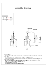
(Charge the refrigerant as below.)
Recover the refrigerant and check there is no refrigerant in the
equipment.
Leave it as it is for 1 to 2 minutes and check the indicator of
the compound gauge does not return.
Set the refrigerant cylinder on the electron balance, connect
the charge hose to connecting ports of the cylinder and the
electron gauge, and then charge the liquid refrigerant from the
service port at liquid side. (Shield with the gauge manifold so
that refrigerant does not flow to gas side.)
Connect the charge hose to the packed valve service ports at gas
side, liquid side, and balance side of the outdoor unit.
Open the packed valves of the balance pipe fully at liquid and gas
sides, and then return the valve at gas side a little to the closed side.
Open fully PMV of the outdoor unit.
• Turn on power of the outdoor unit.
• Short CN30 on I/F P.C. board of the outdoor unit.
•
Turn off power of the outdoor unit within 2 minutes after short-circuiting.
Open fully the handle Low of the gauge manifold, and then turn on
the power of vacuum pump for vacuuming.
When the pressure has lowered until indication of the
compound gauge pointed -0.1MPa (–76cmHg), open fully the
handle Low and turn off the power of vacuum pump.
Connect the charge hose to vacuum pump adaptor.
R410A refrigerant is consisted with HFC mixed refrigerant.
Therefore if the refrigerant gas is charged, the composition
of the charged refrigerant changes and characteristics of
the equipment changes.
4mm-hexagonal wrench is required.

8
1. CONSTRUCTION VIEWS (EXTERNAL VIEWS)
595 to 660 Ceiling open dimension
Space required for
installation and servicing
200
525 Hanging bolt pitch
595 to 660 Ceiling open dimension
700 Panel external dimension
142 64 368.5
145.5
93
105
70
575 Unit external dimension
320.5
595 to 660 Ceiling open dimension
Check port
( 450)
Bottom face
of ceiling
Ceiling panel
Drain discharge port
Hanging bolt
M10 or W3/8
local arrange
Wiring connection
port
4-Ø3.2 hole
(For 4mm
tapping screw)
4-Ø3.2 hole
(For 4mm tapping screw)
For branch ductt
knockout square
hole Ø150
Knockout for fresh
air intake Ø100
Electric parts box
Ø162 (Pitch)
For branch duct
knockout square hole Ø150
Bottom face
of ceiling
Bottom face of ceiling
Refrigerant pipe (Gas)
0151, 0181MH : Ø12.7
0071 to 0121MH : Ø9.5
Refrigerant pipe
(Liquid) Ø6.4
268 27
63
134
145.5
220.5
1000 or more
1000 or more
Obustacle
1000 or more
15 or more
15 or more
Drain-up standing-up size
Note)
As ABS is used for the drain discharge port of the main unit,
the vinyl chloride paste cannot be used.
Use the flexible hose (Band fix) included in the package.
Stand-up
627.5
or less
Bottom face
of ceiling
Indoor unit
Stand-up
850 or less
55
9310570
139.5
190.5
21
158
214 105
177
207
575 Unit external dimension
105235 235
175
149
64
29
525 Hanging bolt pitch
595 to 660 Ceiling open dimension
700 Panel external dimension
256
Ø162
(Pitch)
142
120
97.5 42 148
200
200
Check port
( 450)
Check port
( 450)
16
120
4
2.7
120
• Wired remote
controller
(RBC-AMT31E)

9
BLK
P301
Fan motor
Indoor temp. sensor
Temp. sensor
Temp. sensor
Temp. sensor
Louver motor
Drain pump motor
Float switch
Drain control relay
Pulse motor valve
Symbol
FM
TA
TC1
TCJ
TC2
LM1, LM2
DP
FS
RY302
PMV
Parts name
Color
indication
RED : RED
WHI : WHITE
YEL : YELLOW
BLU : BLUE
BLK : BLACK
GRY : GRAY
PNK : PINK
ORN: ORANGE
BRW: BROWN
GRN: GREEN
1. indicates the terminal bolock letter.
Letter at inside indicates the terminal number.
2. A dotted line and broken line indicate the wiring at site
3. indicates a control P.C. board.
S(N)R(L)
Power supply
single phase
220-240V, 50Hz
220V, 60Hz
Indoor unit
earth screw
CN67
(BLK)
CN304
(GRY)
RY302
DP
CN68
(BLU)
CN334
(WHI)
Motor
drive circuit
CN333
(WHI)
Flow selector
unit earth screw
(Fan drive) Option
Adapter for
wireless
remote controller
Wireed
remote controller
CN44
(BRW)
CN50
(WHI)
CN66
(WHI)
CN32
(WHI)
CN61
(YEL)
Control P.C. board
for Indoor unit
MCC-1402
CN60
(WHI)
CN81
(BLK)
CN33
(WHI)
CN20
(BLU)
CN70
(WHI)
CN73
(RED)
CN80
(GRN)
CN41
(BLU)
CN40
(BLU)
CN309
(YEL)
CN101
(BLK)
CN102
(RED)
CN104
(YEL)
CN34
(RED)
CN100
(BRW)
TC1
FS
TA TCJ TC2
CN82 (BLU)
LM1
LM2
Outdoor
unit
PNL
EXCT
Filter
GRL
CN001
(WHI)
WHI BLK
BLU
BLU
BLK
BLK
T10
WHI
RED
1
2
3
4
5
1
4
5
1
3
5
1 2 3 4 5 6
1 2 3 4 5 6
6 4 3 1 2 5
6 4 3 1 2 5
1 2 3
3 11 2 1 2 1 2
1 3
1 2 3
1 3
1 2 1 2 1 2
1
3
5
1 2
1 2
1
2
1
3
5
5
1
2
3
4
5
654321 54321654321
3 3
1 1
3 3
1 1
3
1
2
1
2
1
5
4
3
2
1
21
1
2
1
2
(CHK)
2
1
(DISP)
CN71
CN72
2
1
1
2
3
1
2
3
1
2
U2U1
BAU2U1
5
4
3
2
1
5
4
3
2
1
5
4
3
2
1
5
4
3
2
1
5
4
3
2
1
5
4
3
2
1
5
4
3
2
1
5
4
3
2
1
RY303
Fuse
T6.3A
250V
~
Fuse
T3.15A
250V
~
DC20V
DC15V
DC12V
DC 7 V
Power
supply
circuit
PMV
2. WIRING DIAGRAM

10
3. PARTS RATING
3-1. Parts Rating
Model MMU-
Fan motor
Motor for horizontal grille
Pulse motor
Pulse motor valve
TA sensor
TC1 sensor
TC2 sensor
TCJ sensor
Float switch
Drain pump motor
AP0071MH AP0091MH AP0121MH AP0151MH AP0181MH
SWF-230-60-1R
MP24Z3N
EDM-MD12TF-3
EDM-B25YGTF-3 EDM-B40YGTF-3
Lead wire length : 155mm Vinyl tube
Ø4 size lead wire length : 1400mm Vinyl tube
Ø6 size lead wire length : 1500mm Vinyl tube (Black)
Ø6 size lead wire length : 1400mm Vinyl tube (Red)
FS-0218-103
ADP-1409
3-2. Name of Each Part
Air outlet/Air outlet flap
Select air blow direction in cooling or
heating operation each.
Air filter
Removes dust and trash.
(Air filter is provided in the air grille.)
Clip
The clip is to open/close the air inlet grille.
Air inlet grille
Air in the room is sucked from here.
Earth screw
It is included in the electric parts box.

11
1
SET DATA display
Displayed during setup of the timer.
2
Operation mode select display
The selected operation mode is displayed.
3
CHECK display
Displayed while the protective device works or a
trouble occurs.
4
Timer time display
Time of the timer is displayed. (When a trouble
occurs, the check code is displayed.)
5
Timer SETIN setup display
When pushing the Timer SET button, the display
of the timer is selected in order of
[OFF]
→ [OFF] repeat OFF timer
→ [ON]
→ No display.
6
Filter display
If “FILTER ” is displayed, clean the air filter.
7
TEST run display
Displayed during a test run.
8
Flap position display
Displays flap position.
9
SWING display
Displayed during up/down movement of the flap.
10
Set up temperature display
The selected set up temp. is displayed.
11
Remote controller sensor display
Displayed while the sensor of the remote
controller is used.
12
PRE-HEAT display
Displayed when the heating operation starts.
While this indication is displayed, the indoor fan
stops.
13
Operation ready display
Displayed when cooling or heating operation is
impossible because the outdoor temperature goes
out of the operable range.
14
No function display
Displayed if there is no function even if the button is
pushed.
15
Air volume select display
The selected air volume mode is displayed.
(AUTO)
(HIGH)
(MED.) (LOW)
16
Mode select control display
Displayed when pushing “Operation mode select ”
button while the operation mode is fixed to heating
or cooling by the system manager of the air condi-
tioner.
17
Central control display
Displayed when using the remote controller together
with the central control remote controller, etc.
If Remote controller is prohibited at the
centralcontrol side,
flashes when operating
ON / OFF
,
MODE
, / buttons and
the change is not accepted.
(The contents available to be set up on the remote
controller differ according to the central control
mode. For details, refer to Owner’s Manual of the
central control remote controller.)
Display
section
Operation
section
ON / OFF
FAN
TEMP.
SWING/FIXTIME
MODE
VENT
UNITSET CL
FILTER
RESET
TEST
TIMER SET
CODE No.
UNIT No.
TEST
SETTING
DATA
SET
R.C. No.
H
2
15
5
78 9
3
1
4
6
10
11
13
16
12
14
17
CODE No.
UNIT No.
TEST
SETTING
DATA
SET
R.C. No.
H
3-3. Parts Name of Remote Controller
Display section
In the display example, all indicators are displayed for the explanation.
In reality only, the selected contents are indicated.
• When turning on the leak breaker at the first time, [SET DATA] flashes on the
display part of the remote controller. While this display is flashing, the model is
being automatically confirmed. Accordingly, wait for a while after [SET DATA]
display has disappeared, and then use the remote controller.

12
Operation section
Push each button to select a desired operation.
This remote controller can operate the maximum 8 indoor units.
• The details of the operation needs to be set up once, afterward, the air conditioner can be used by pushing
ON / OFF
button only.
1
Air volume select button
Selects the desired air volume mode.
2
Timer set button
TIMER SET button is used when the timer is set
up.
3
Check button
The CHECK button is used for the check opera-
tion. During normal operation, do not use this
button.
4
Fan button
FAN button is used when a fan which is sold on
the market or etc. is connected.
5
Filter reset button
Resets (Erases) “FILTER ” display.
6
Wind direction and Swing
UNIT
:
If the multiple indoor units are operated by only
one remote controller, select the units when the
air direction is adjusted.
SWING/FIX
:
Set up the auto swing and angle of the flap.
7
Operation lamp
Lamp is lit during the operation. Lamp is off when
stopped.
Although it flashes when operating the protection
device or abnormal time.
8
ON / OFF
button
When the button is pushed, the operation starts,
and it stops by pushing the button again.
When the operation has stopped, the operation
lamp and all the displays disappear.
9
Operation select button
Selects desired operation mode.
10
Set up temperature button
Adjusts the room temperature.
Set the desired set temperature by pushing
or .
OPTION :
Remote controller sensor
Usually the TEMP. sensor of the indoor unit senses
the temperature. The temperature on the surround-
ing of the remote controller can also be sensed.
For details, contact the dealer from which you have
purchased the air conditioner.
• In case that one remote controller controls the
multiple indoor units, the setup operation is
unavailable in group control.
1
7
3
5
2
8
9
6
4
10
ON / OFF
FAN
TEMP.
SWING/FIXTIME
MODE
VENT
UNITSET CL
FILTER
RESET
TEST
TIMER SET

13
3-4. Correct Usage
When you use the air conditioner for the first time or when you change the SET DATA value, follow the proce-
dure below. From the next time, the operation displayed on the remote controller will start by pushing the
ON / OFF
button only.
Preparation
Turn on the main power switch and/or the leakage breaker.
• When the power supply is turned on, a partition line is displayed on the display part of the remote controller.
* After the power supply is turned on, the remote controller does not accept an operation for approx. 1 minute,
but it is not a failure.
REQUIREMENT
• While using the air conditioner, operate it only with
ON / OFF
button without turning off the main power
switch and the leak breaker.
1
Push
ON / OFF
button.
The operation lamp goes on, and the operation starts.
2
Select an operation mode with the “MODE
MODE
” button.
One push of the button, and the display
changes in the order shown on the right.
• In HEAT mode, if the room temperature reaches to
the set temperature, the outdoor unit stops and the air
flow becomes ULTRA LOW and the air volume decreases.
• In the heating mode, the fan stops so that cool air is not discharged and Heat is displayed.
3
Select air volume with “FAN
FAN
” button.
One push of the button, and the display
changes in the order shown on the right.
• When air volume is “AUTO ”, air volume differs according to the temperature difference between set
temp. and room temp.
• In DRY mode, “AUTO ” is displayed and the air volume is LOW.
• In heating operation, if the room temperature is not heated sufficiently with VOLUME “LOW ” operation,
select “MED. ” or “HIGH ” operation.
4
Determine the set up temperature by pushing the “TEMP. ” or “TEMP. ” button.
Stop
Push
ON / OFF
button.
The operation lamp goes off, and the operation stops.
1
3
2
4
ON / OFF
FAN
TEMP.
SWING/FIXTIME
MODE
VENT
UNITSET CL
FILTER
RESET
TEST
TIMER SET
Heat-pump model
DRY COOL FAN
Cooling only model
(Dehumidity)
AUTO
HEAT DRY COOL FAN
LOW MED. HIGH
AUTO

14
1
2
3
ON / OFF
FAN
TEMP.
SWING/FIXTIME
MODE
VENT
UNITSET CL
FILTER
RESET
TEST
TIMER SET
3-5. Automatic Operation (Super Heat Recovery Type Only)
When you set the air conditioner in mode or switch over from AUTO operation because of some settings
change, it will automatically select either cooling, heating, or fan only operation depending on the indoor tem-
perature.
Start
1
ON / OFF
button
Push this button to start the air conditioner.
2
Mode select button (MODE)
Select Auto.
3
Temperature button
Set the desired temperature.
• In case of cooling, start the operation after approx. 1 minute.
• In case of heating, the operation mode is selected in accordance with the room temperature and operation
starts after approximately 3 to 5 minutes.
• When you select the Auto mode, it is unnecessary to set the fan speed.
The FAN speed display will show AUTO and the fan speed will be automatically controlled.
• After the heating operation has stopped, FAN operation may continue for approx. 30 seconds.
• When the room temperature reaches the set temperature and the outdoor unit stops, the super low wind is
discharged and the air volume decreases excessively.
During defrost operation, the fan stops so that cool air is not discharged and “HEAT READY” is displayed.
• If the Auto mode is uncomfortable, you can select the desired conditions manually.
NOTE
When restarting the operation after stop
• When restarting the operation immediately after stop, the air conditioner does not operate for approx. 3
minutes to protect the machine.
Stop
Push
ON / OFF
button.
Push this button again to stop the air conditioner.

15
3-6. TIMER Operation
A type of timer operation can be selected from the following three types.
OFF timer : The operation stops when the time of timer has reached the set time.
Repeat OFF timer : Every time, the operation stops after the set time has passed.
ON timer : The operation starts when the time of timer has reached the set time.
Timer operation
1
Push TIMER SET button.
• The timer display (type) changes for every
push of the button.
• SET DATA and timer time displays flash.
2
Push
TIME
to select “SET TIME”.
For every push of button, the set time increases in the unit of 0.5 hr (30 minutes).
The maximum set time is 72.0 hr.
For every push of button, the set time decreases in the unit of 0.5 hr (30 minutes).
The minimum set time is 0.5 hr.
3
Push SET button.
•
SETTING
display disappears and timer time display goes on.
(When ON timer is activated, timer time, ON timer are displayed and other displays disappear.)
Cancel of timer operation
4
Push CL button.
• TIMER display disappears.
NOTICE
• When the operation stops after the timer reached the preset time, the Repeat OFF timer resumes the
operation by pushing
ON / OFF
button and stops the operation after the time of the timer has reached the
set time.
4
3
2
1
ON / OFF
FAN
TEMP.
SWING/FIXTIME
MODE
VENT
UNITSET CL
FILTER
RESET
TEST
TIMER SET
OFF
(OFF timer) (Repeat OFF timer)
No display
(ON timer)
OFF ON

16
3-7. Adjustment of Wind Direction
• While the air conditioner stops, the horizontal flap (Up/Down air direction adjustment plate) automati-
cally directs upward.
• While the air conditioner is in ready status for heating, the horizontal flap (Up/Down air direction
adjustment plate) directs upward. The swinging operation starts after heating ready status has been
cleared, but “SWING ” is displayed on the remote controller even if the status is ready to heating.
How to set up the air direction
Push
SWING/FIX
button during operation.
ON / OFF
FAN
TEMP.
SWING/FIXTIME
MODE
VENT
UNITSET CL
FILTER
RESET
TEST
TIMER SET
In FAN operation
1, 2, 3 4
In all modes
Display when stopping the swing
Initial setup
Series of
operation
Fan/Heat
operation
Cool/Dry
operation
Unit No. 1-1No display Unit No. 1-2
Unit No. 1-4 Unit No. 1-3
1
Every pushing the button, the air direction changes.
In Heating operation
Set the horizontal flap (Up/Down
air direction adjustment plate)
downward. If directing it upward,
the hot air may not come to the
foot come to the foot.
In Cooling / Dry operation
Set the horizontal flap (Up/Down
air direction adjustment plate)
upward. If directing it downward,
the dew may fall on near the air
air outlet port or it drips.
How to start swinging
2
Push
SWING/FIX
button.
Set direction of the horizontal flap (Up/Down air
direction adjustment plate) to the lowest position
and then push
SWING/FIX
button again.
• [SWING ] is displayed and the air direction
automatically changes upward/downward.
In case when one remote controller controls the
multiple indoor units, each indoor unit can be se-
lected and its air direction can be set up.
How to stop swinging
3
Push
SWING/FIX
button again during swinging of the
horizontal flap.
• The horizontal flap can be stopped at the desired
position. After then the air direction can be again set
up from the uppermost position by pushing
SWING/FIX
button.
* While the horizontal flap is set downward in cool-
ing/drying operation, it does not stop.
If stopping the horizontal flap which directs down-
ward during swinging, it stops after moving to the
3rd position from the top position.
4
UNIT
• To set up the air direction individually, push
UNIT
button to display each indoor unit No. in a group
control. Then set up the air direction to a displayed
indoor unit.
• If there is no display, all the indoor units can be
operated collectively.
• Every pushing
UNIT
button, the display exchanges
as shown in the figure.
Initial setup
Initial setup

17
3-8. Information
Confirmation before operation
• Turn on the power switch 12 hours before starting
the operation.
• Make sure whether earth wire is connected.
• Make sure the air filter is connected to the indoor
unit.
Heating capacity
• A heat pump system which absorbs heat from
outside of the room and then discharges heat into
the room is adopted for heating. If the outside
temperature falls, the heating capacity decreases.
• When the outside temperature is too low, it is
recommended to use this air conditioner together
with other heating equipment.
Defrost during heating operation
• In heating operation, if there is frost on the outdoor
unit, the operation changes automatically to the
defrost operation (Approx. 2 to 10 minutes) to
increase the heating efficiency.
• During defrost operation, the fan of the indoor unit
stops.
3-minutes protection
• When restarting the operation just after the
operation has been stopped or the main power
switch has turned on, the outdoor unit does not
work for approx. 3 minutes in order to protect the
air conditioner.
Power failure
• If a power failure occurred during operation, all
operations stop.
• When the power is returned after a power failure,
the operation lamp notifies the power-ON by
flashing operation lamp on the remote controller.
• When restarting the operation, push
ON / OFF
button again.
Fan rotation in stopped unit
• In heating operation even in the stopped indoor
unit, the fan rotates once for several minutes per
approx. an hour when the other indoor unit is
operating to protect the air conditioner.
Protective device (High pressure switch)
This device stops automatically an operation when
excessive force is applied on the air conditioner.
If the protective device works, the operation stops
and the operation lamp flashes.
When the protective device works, the indication
TEST
and the check code are displayed on the display
section of the remote controller. In the following
cases, the protective device may work.
In cooling operation
• The suction port or discharge port of the outdoor
unit is closed.
• A strong wind continuously blows to the discharge
port of the outdoor unit.
In heating operation
• Dust or waste adheres excessively to air filter of
the indoor unit.
• The discharge port of the indoor unit is closed.
If the protective device works, turn off the main
power switch, solve the cause, and then start the
operation again.
Cooling/Heating operation of Super
Modular Multi system air conditioner
• Although each indoor unit can be individually
controlled in the Super Modular Multi system air
conditioner, the cooling operation and the heating
operation cannot be simultaneously performed in
the multiple indoor units which are connected to
an outdoor unit.
• If the cooling operation and the heating operation
are simultaneously performed, the indoor unit
which executes cooling operation stops, and on
the operation section lights up. On the other hand,
the indoor unit which executes heating operation
continues running. In a case that the manager of
the air conditioner has fixed the operation to
cooling or heating, an operation other than that set
up is unavailable. If an operation other than that
set up is executed, on the operation section
lights up and the operation stops.
Characteristics of heating operation
• The wind is not out just after starting an operation.
The hot wind starts to blow 3 to 5 minutes after
(Time differs according to indoor/outdoor tempera-
ture.) the indoor heat exchanger has warmed up.
• During operation, the outdoor unit may stop if the
outside temperature rises.

18
3-9. Air Conditioner Operations and Performance
3 minutes protection function
3-minutes protection function prevents the air conditioner from starting for initial 3 minutes after the main power
switch/circuit breaker is turned on for re-starting the air conditioner.
Power failure
Power failure during operation will stop the unit completely.
• To restart the operation, push the START/STOP button on the remote controller.
• Lightning or a wireless car telephone operating nearby may cause the unit to malfunction. Turn off the main
power switch or circuit breaker and then turn them on again. Push the START/STOP button on the remote
controller to restart.
Heating characteristics
Preheating operation
The air conditioner will not deliver warm air immediately after it is turned on. Warm air will start to flow out after
approximately 5 minutes when the indoor heat exchanger warmed up.
Warm air control (In heating operation)
When the room temperature reaches the set temperature, the fan speed is automatically reduced to prevent to
blow cold draft. At this time, the outdoor unit will stop.
Defrosting operation
If the outdoor unit is frosted during the heating operation, defrosting starts automatically (for approximately
2 to 10 minutes) to maintain the heating capacity.
• The fans in both indoor and outdoor units will stop during the defrosting operation.
• During the defrosting operation, the defrosted water will be drained from the bottom plate of the outdoor unit.
Heating capacity
In the heating operation, the heat is absorbed from the outside and brought into the room. This way of heating
is called heat pump system. When the outside temperature is too low, it is recommended to use another heating
apparatus in combination with the air conditioner.
Attention to snowfall and freeze on the outdoor unit
• In snowy areas, the air inlet and air outlet of the outdoor unit are often covered with snow or frozen up.
If snow or freeze on the outdoor unit is left as it is, it may cause machine failure or poor warming.
• In cold areas, pay attention to the drain hose so that it perfectly drains water without water remaining inside for
freeze prevention. If water freezes in the drain hose or inside the outdoor unit, it may cause machine failure or
poor warming.
Air conditioner operating conditions
For proper performance, operate the air conditioner under the following temperature conditions:
If air conditioner is used outside of the above conditions, safety protection may work.
Cooling operation
Dry operation
Heating operation
Outdoor temperature : –5°C to 43°C
Room temperature : 21°C to 32°C (Dry valve temp.), 15°C to 24°C (Wet valve temp.)
CAUTION
Room relative humidity – less than 80 %. If the air conditioner operates
in excess of this figure, the surface of the air conditioner may cause dewing.
Outdoor temperature : 15°C to 43°C (Maximum suction air temp. 46°C)
Room temperature : 17°C to 32°C
Outdoor temperature : –15°C to 15°C (Wet valve temp.)
Room temperature : 15°C to 28°C (Dry valve temp.)

19
3-10. When the Following Symptoms are Found
Check the points described below before asking repair servicing.
Symptom
Outdoor unit • White misty cold air
or water is out.
• Sometimes, noise
“Pushu !” is heard.
Indoor unit •“Swish” sound is
heard sometimes.
• Slight “Pishi!” sound
is heard.
• Discharge air smells.
• The operation lamp
flashes
•“STANDBY
”
indication is lit.
• Sound or cool air is
output from the
stand by indoor unit.
• When power of the
air conditioner is
turned on, “Ticktock”
sound is heard.
Operates or stops automatically.
Does not operate.
Air is not cooled or warmed sufficiently.
Cause
• Fan of the outdoor unit stops automatically and performs defrost
operation.
• Solenoid valve works when defrost operation starts or finishes.
• When the operation has started, during the operation, or immediately
after the operation has stopped, a sound such as water flows may be
heard, and the operation sound may become larger for 2 or 3 minutes
immediately after the operation has started. They are flowing sound of
refrigerant or draining sound of dehumidifier.
• This is sound generated when heat exchanger, etc. expand and
contract slightly due to change of temperature.
• Various smell such as one of wall, carpet, clothes, cigarette, or
cosmetics adhere to the air conditioner.
• Flashes when power is turned on again after power failure, or when
power switch is turned on.
• When cooling operation cannot be performed because another indoor
unit performs heating operation.
• When the manager of the air conditioner has fixed the operation to
COOL or HEAT, and an operation contrary to the setup operation is
performed.
• When fan operation stopped to prevent discharge of hot air.
• Since refrigerant is flowed temporarily to prevent stay of oil or
refrigerant in the stand by indoor unit, sound of flowing refrigerant,
“Kyururu” or “Shaa” may be heard or white steam when other indoor
unit operates in HEAT mode, and cold air in COOL mode may be
blow-out.
• Sound is generated when the expansion valve operates when power
has been turned on.
• Is the timer “ON” or “OFF”?
• Is it a power failure?
• Is the power switch turned off?
• Is the power fuse or breaker blown?
• Has the protective device operated? (The operation lamp goes on.)
• Is the timer “ON”? (The operation lamp goes on.)
• Are COOL and HEAT selected simultaneously? (“STANDBY
”
indication is lit on the display column of the remote controller.)
• Is the suction port or discharge port of the outdoor unit obstructed?
• Are any door or window open?
• Is the air filter clogged with dust?
• Is discharge flap of the indoor unit set at appropriate position?
• Is air selection set to “LOW” “MED.”, and is the operation mode set to
“FAN”?
• Is the setup temp. the appropriate temperature?
• Are COOL and HEAT selected simultaneously? (“STANDBY
”
indication is lit on the display column of the remote controller.)
It is not a failure.
Check again.
When the following symptoms are found, stop the operation immediately, turn off the power switch, and contact
the dealer which you have purchased the air conditioner.
• Activation of switch is unstable.
• Fuse or breaker is blown periodically.
• Foreign matters or water entered by mistake.
• When if activation cause of the protective device has been removed, the operation is not performed.
• Other unusual status occurred.
Silent
It’s strange.

20
Accessory parts and Parts to be procured locally
H Accessory parts
Refrigerant piping
• Piping material used for the conventional refrigerant cannot be used.
• Use copper pipe only with a wall thickness of 0.8 mm or more for Ø6.4, Ø9.5, Ø12.7.
• Flare nut and flare operations are also different from those of the conventional refrigerant.
Use the flare nut fitted to the indoor unit of the air conditioner.
Shape
This manual
——
M5 × 16L
Part name
Installation Manual
Heat insulating pipe
Installation pattern
Installation gauge
Pattern fixing screw
Heat insulator
Washer
Hose band
Flexible hose
Heat insulator A
Heat insulator B
Q’ty
1
2
1
2
4
1
8
1
1
1
1
Usage
(Ensure hand over to customer)
For heat insulation of the pipe connecting section
For checking of ceiling opening and the main unit position
For positioning of the ceiling position
(To be used with the installation pattern)
For attach the installation pattern
For heat insulation of drain connecting section
For hanging unit
For connecting drain pipe
For adjusting core-out of drain pipe
For sealing of wire connecting port
For sealing of wire connecting port
1
PRECAUTIONS FOR SAFETY
• Ensure that all Local, National and International regulations are satisfied.
• Important safety information are described in this installation manual.
Please ensure this manual is read thoroughly and kept for future reference.
• After the installation work, perform a trial operation to check for any problem.
Follow the Owner’s Manual to explain how to use and maintain the unit to the customer.
• Turn off the main power supply switch (or breaker) before any unit maintenance.
• Ask the customer to keep the Installation Manual together with the Owner’s Manual.
CAUTION New Refrigerant Air Conditioner Installation
• THIS AIR CONDITIONER FEATURES A NEW HFC REFRIGERANT (R410A) WHICH DOES NOT
DEPLETE OZONE LAYER.
The pressure of R410A is 1.6 times higher than that of former refrigerant R22. The refrigerating oil has also been
changed. Therefore be sure that any former refrigerant, refrigerant oil or any other contaminants do not enter the
refrigerating cycle of the air conditioner, during either installation or service work. If incorrect tools or operating
procedures are used, there is a possibility of a serious accident. Use only tools and materials that have been
designed to operate with R410A.
To prevent the risk of charging with an incorrect refrigerant, the dimensions of the charging port connections are different
to those used for conventional refrigerant. Therefore only tools designed to operate with R410A can be used.
For connecting pipes, use piping specifically designed for R410A.
During installation, ensure pipes are clean and ensure contaminants do not enter in the pipes as the system is
affected by impurities such as water, oxide scales, dirt, oil, etc. Do not use existing pipe work from previous
installation as this will cause problems due to pressure resistances and impurities within the pipe.
CAUTION To Disconnect the Appliance from Main Power Supply.
This appliance must be connected to the main power supply by means of a switch with a contact separation of at
least 3 mm.
WARNING
• Ask an authorized dealer or qualified installation professional to install/maintain the air conditioner.
Inappropriate installation may result in water leakage, electric shock or fire.
• Turn off the main power supply switch or breaker before attempting any electrical work.
Make sure all power switches are off. Failure to do so may cause an electric shock.
• Connect all of the installation wiring correctly.
If the installation wiring is incorrect electrical parts may be damaged.
• During the transportation and installation of the air conditioning unit, ensure that gaseous matter
other than the specified refrigerant does not enter into the refrigeration cycle.
If a refrigerant becomes contaminated with foreign gases, the gas pressure within the refrigerant cycle will become
abnormally high and may result in the fracture of pipe work and possible human injury.
• Do not modify this unit by removing any of the safety guards or by overriding any of the safety
interlock switches.
• Exposure of the unit to water or other forms of moisture before installation may cause a short-circuit
of the electrical parts.
Do not store it in a wet basement or expose to rain or water.
• After unpacking the unit, examine for possible damage.
• Do not install in a place that might increase the vibration of the unit.
• To avoid personal injury (with sharp edges), be careful when handling parts.
• Perform installation work properly according to the Installation Manual.
Inappropriate installation may result in water leakage, electric shock or fire.
• When the air conditioner is installed in a small room, provide appropriate measures to ensure that in
the event of a refrigerant leak the rooms does not exceed the critical level.
/