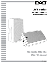
Redfire 12

ANT Redfire 12, Redfire 10, Redfire 15 User manual

  • Hello! I am an AI chatbot trained to assist you with the ANT Redfire 12 User manual. I’ve already reviewed the document and can help you find the information you need or explain it in simple terms. Just ask your questions, and providing more details will help me assist you more effectively!
2-WAYS ACTIVE LOUDSPEAKER SYSTEM
DIFFUSORI BI-AMPLIFICATI IN PLASTICA
REDFIRE 10 | REDFIRE 12 | REDFIRE 15
EN USER MANUAL | Section 1
IT MANUALE D’USO | Sezione 1
ENGLISH
REDFIRE Series | User manual
2
3
Series
User manual | REDFIRE Series
CONTENTS
1 | Introduction 3
2 | Installation 3
3 | Description 4
3.1 | Inputs & controls 4
3.2 | Power supply section 6
4 | Troubleshooting 7
5 | Technical specications 8
6 | Notes 16
The warnings in this manual must be observed together with the
User manual - Section 2”.
PACKAGE CONTENT
1x Active loudspeaker system
1x Mains cable (VDE)
1x User manual - Section 1
1x User manual - Section 2
A
C
B
1 | INTRODUCTION
Thank you for choosing a A.N.T Advanced Native Technologies – product!
In our REDFIRE series of speakers, we have put our passion and our
technological background gained over the years, to offer products that meet
your needs, maintaining the quality over time.
REDFIRE 10, REDFIRE 12 and REDFIRE 15 models ensure an extended
frequency response with a clean and undistorted sound, even at high sound
level pressures. Expressly designed to be immediately used in a very user
friendly way, this series is the answer to the needs of those who want a sound
system capable of providing excellent performance, versatility of connections
and controls, and the best value for its product range.
Please, dedicate some minutes to read this instruction manual in order to quickly
achieve the best performances from this product.
For safety precautions, warranty and disposal, please refer to attached Section 2.
For further information about all A.N.T products catalog, please visit our website:
www.ant-sound.com
2 | INSTALLATION
REDFIRE models are equipped with:
A | Upper/Lateral Integrated handles
B | Pole mount hole
C | Upper/Lower fly points for installed applications
NEVER USE HANDLES TO
SUSPEND THE SPEAKER!
ENGLISH
REDFIRE Series | User manual
4
5
Series
User manual | REDFIRE Series
5 JACK BALANCED LINE INPUT
6.35mm socket balanced line input.
6 AUX IN STEREO
Unbalanced input with stereo 3.5mm jack for any external devices
(smartphones, tablets, PCs, etc.)
7 HIGH
High frequency equalizer. Use this control to boost or cut mid-hig frequencies.
8 LOW
Low frequency equalizer. Use this control to boost or cut mid-low frequencies.
9 MASTER VOL
Speaker master volume control.
10 CLIP
This LED turns on when the speaker signal is distorted. In this case, reduce
both the MASTER level and the active channel(s) level(s).
11 ON
This LED is lit when the unit is plugged to mains, and the power switch is ON.
12 LINE OUTPUT
This XLR-M connector provides a balanced line-level signal with the mix
of inputs before the MASTER control. It is useful for connection to an audio
system or to another active speaker.
3.1 | INPUTS & CONTROLS
1 MIC LEVEL
This knob adjusts the level of the microphone channel, turn it to the right to raise
the level, to the left to decrease it.
2 MIC INPUT
Balanced microphone input (combo 6.35mm jack/ XLR).
You may also use a microphone cable with unbalanced 6.35mm jack.
3 LINE/AUX LEVEL
This knob adjusts the level of the line channel, turn it to the right to raise the level,
to the left to decrease it.
4 XLR BALANCED LINE INPUT
XLR-F socket balanced line input.
3 | DESCRIPTION
4 125 6
1
3 7 8 910 11
2
ENGLISH
REDFIRE Series | User manual
6
7
Series
User manual | REDFIRE Series
4 | TROUBLESHOOTING
PROBLEM LEDS SOLUTION
No sound or very low
sound level
Power LED
turned off
Make sure the device is properly
connected to the mains outlet
Power LED turned on,
but low MASTER VOL
Raise MASTER VOL level
Power LED turned on,
MASTER VOL raised but
low input channel signal
Check the connections between
the sources and the inputs.
Raise channels LEVEL
Distortion Clip LED on
Cut MIC channel, LINE channel
and/or MASTER levels.
Make sure you haven’t
connected a line level signal
to the MIC input
Booming sound Cut LOW level
Harsh sound Cut HIGH level
1 POWER ON/OFF
Use this switch to turn On/Off the unit.
2 FUSE
AC Protection fuse.
Caution: Replace the fuse only with one of the same type and with the same
value. If the fuse blows repeatedly, contact an authorized service center.
3 MAINS INPUT
IEC mains socket with integrated EMI lter.
Each package is supplied with the power cord for your area. Insert the mains cable
into this socket, but make sure the device is switched off before connecting the
cable to the mains. For your safety, never disconnect the earth lead.
WARNING!
Never remove the product’s front protection mesh. In order to prevent electric
shock hazard, in the event of accidental damage or replacement of the
protection mesh (which must be carried out by a service center), disconnect
the power supply immediately.
CAUTION: To reduce the risk of electric shock, do not connect the appliance
to the power supply while the mesh is removed.
1 2
3
3.2 | ALIMENTAZIONE
8
Series
User manual | REDFIRE Series
ITALIANO
Serie REDFIRE | Manuale d’uso
9
INDICE
1 | Introduzione 10
2 | Installazione 10
3 | Descrizione 11
3.1 | Ingressi e controlli 11
3.2 | Alimentazione 13
4 | Soluzione dei problemi 14
5 | Dati tecnici 15
6 | Note 16
Le avvertenze nel presente manuale devono essere osservate
congiuntamente al “Manuale d’uso - Sezione 2”.
CONTENUTO DELL’IMBALLO
1x Diffusore Fullrange Attivo
1x Cavo di alimentazione (VDE)
1x Manuale d’uso - Sezione 1
1x Manuale d’uso - Sezione 2
5
| TECHNICAL SPECIFICATIONS
REDFIRE 10 REDFIRE 12 REDFIRE 15
System type
Vented enclosure,
2-way
Vented enclosure,
2-way
Vented enclosure,
2-way
LF
10” custom woofer
1.5” VC
12” custom woofer
2” VC
15” custom woofer
2” VC
HF
1” compression
driver - 1” VC
1” compression
driver - 1.35” VC
1” compression
driver - 1.35” VC
Coverage 80° H x 55° V 90° H x 60° V 90° H x 60° V
Amplier (LF+HF) Class D + Class A/B Class D + Class A/B Class D + Class A/B
Peak Power (LF+HF) 500 W 800 W 800 W
Frequency response 60 Hz - 20 kHz 50 Hz -20 kHz 45 Hz -20 kHz
SPL - Max 120 dB 122 dB 123 dB
I/O Connectors
MIC: Combo
LINE IN: XLR-F +
jack 6,35mm (1/4”)
AUX IN: mini-jack
3,5mm
LINE OUT: XLR-M
MIC: Combo
LINE IN: XLR-F + jack
6,35mm (1/4”)
AUX IN: mini-jack
3,5mm
LINE OUT: XLR-M
MIC: Combo
LINE IN: XLR-F + jack
6,35mm (1/4”)
AUX IN: mini-jack
3,5mm
LINE OUT: XLR-M
Controls
MIC LEVEL,
LINE/AUX LEVEL,
LOW EQ, HIGH EQ,
MASTER LEVEL
MIC LEVEL,
LINE/AUX LEVEL,
LOW EQ, HIGH EQ,
MASTER LEVEL
MIC LEVEL,
LINE/AUX LEVEL,
LOW EQ, HIGH EQ,
MASTER LEVEL
Fuse T2A L 250V~ T3.15A L 250V~ T3.15A L 250V~
Suspension system 2 x M8 - under 4 x M10 - top/under
5 x M10 - top/under/rear
Cabinet Polypropylene Polypropylene Polypropylene
Dimensions (WxHxD)
321 x 505 x 307 mm
12.6” x 19.8” x 12.1”
385 x 597 x 366 mm
15.1” x 23.5” x 14,4”
460 x 705 x 440 mm
18.1” x 31.3” x 17.3”
Weight 12 kg (26.4 lb) 17,3 kg (38.1 lb) 21,1 kg (46.4 lb)
EMI CLASSIFICATION
According to the standard EN55103 this equipment is designed and suitable to operate in E3 (or
lower E2, E1) electromagnetic environments.
10
11
SERIE
ITALIANO
Serie REDFIRE | Manuale d’uso
3.1 | INGRESSI & CONTROLLI
1 MIC LEVEL
Questa manopola regola il livello del canale microfonico, ruotatela verso
destra per alzare il livello, verso sinistra per diminuirlo.
2 MIC INPUT
Ingresso microfono bilanciato (combo XLR/jack da 6,35 mm).
È possibile usare anche un cavo microfonico jack non bilanciato.
3 LINE/AUX LEVEL
Questa manopola regola il livello del canale di linea, ruotatela verso destra
per alzare il livello, verso sinistra per diminuirlo.
4 XLR BALANCED LINE INPUT
Ingresso bilanciato con presa XLR-F.
1 | INTRODUZIONE
Grazie per aver acquistato un prodotto A.N.TAdvanced Native Technologies!
Nei diffusori acustici della serie REDFIRE abbiamo profuso la nostra passione ed il
nostro know-how maturato nel corso degli anni per offrirvi un prodotto che soddis le
vostre esigenze e mantenga la sua qualità nel tempo.
I modelli REDFIRE 10, REDFIRE 12 e REDFIRE 15 garantiscono un’estesa risposta in
frequenza con un suono pulito e senza distorsioni anche a volumi molto alti.
Progettati appositamente per un utilizzo estremamente immediato e semplice,
rispondono alle esigenze di quanti desiderano un sistema audio in grado di fornire
ottime prestazioni, ampia versatilità di connessioni e controlli, e il miglior rapporto
qualità-prezzo possibile per questa categoria.
Ritagliatevi qualche minuto per leggere questo manuale di istruzioni in modo tale da
ottenere rapidamente il massimo delle performance da questo prodotto.
Per le istruzioni relative a sicurezza, le precauzioni, la garanzia e lo smaltimento fate
riferimento all’allegato sezione 2.
Per ulteriori informazioni su tutti i prodotti del catalogo A.N.T consultate il nostro sito:
www.ant-sound.com
2 | INSTALLAZIONE
I modelli REDFIRE sono forniti di:
A | Maniglie laterali e superiori integrate
B | Foro per montaggio su palo
C | Punti di sospensione per l’installazione ssa del diffusore
3 | DESCRIZIONE
1
4 125 6
3 7 8 910
2
Manuale d’uso | Serie REDFIRE
A
C
B
NON USATE LE MANIGLIE PER
SOSPENDERE I DIFFUSORI!
11
12 13
SERIE
ITALIANO
Serie REDFIRE | Manuale d’uso
1 2
3
3.2 | ALIMENTAZIONE
5 JACK BALANCED LINE INPUT
Ingresso bilanciato con presa jack da 6,35mm.
6 AUX IN STEREO
Ingresso sbilanciato con presa stereo da 3,5mm per qualsiasi dispositivo esterno
(smartphone, tablet, pc, ecc).
7 HIGH
Equalizzatore delle frequenze alte. Utilizzate questo controllo per enfatizzare
o attenuare le frequenze in gamma medio-alta.
8 LOW
Equalizzatore delle frequenze basse. Utilizzate questo controllo per enfatizzare
o attenuare le frequenze in gamma medio-bassa.
9 MASTER VOL
Controllo generale di volume del diffusore.
10 CLIP
Questo led si accende quando il segnale del diffusore raggiunge la distorsione.
In questo caso riducete sia il segnale MASTER che quello dei canali in funzione.
11 ON
Questo led si accende quando l’apparecchio è collegato alla rete elettrica
e l’interruttore di accensione su ON.
12 LINE OUTPUT
Questa uscita XLR-M fornisce un segnale bilanciato di livello linea con il mix degli
ingressi prelevato prima del controllo MASTER.
È utile per il collegamento ad un impianto audio o ad un altro diffusore attivo.
Manuale d’uso | Serie REDFIRE
1 POWER ON/OFF
Interruttore per accensione/spegnimento dell’apparecchio.
2 FUSE
Fusibile di protezione.
Attenzione: Sostituire il fusibile unicamente con uno dello stesso tipo
e con gli stessi valori. Se il fusibile continua a saltare, rivolgetevi ad
un centro di assistenza autorizzato.
3 MAINS INPUT
Presa IEC di ingresso con ltro di rete integrato. Ogni confezione è fornita del
cavo di alimentazione necessario, specico per la vostra zona.
Inserite in questa presa il cavo per l’alimentazione elettrica ma accertatevi che
l’apparecchio sia spento prima di collegare il cavo alla rete.
Per la vostra sicurezza, non scollegate mai il polo centrale di terra.
ATTENZIONE!
Non rimuovere mai la griglia frontale di protezione del prodotto. Per
prevenire il pericolo di scossa elettrica, in caso di danneggiamento
accidentale o sostituzione della griglia di protezione (da effettuarsi presso
il servizio assistenza), disconnettere immediatamente l’alimentazione.
ATTENZIONE: Per ridurre il rischio di scosse elettriche, non connettere
mai l’alimentazione di rete all’apparecchio mentre la griglia è rimossa.
14
15
SERIE
5 | DATI TECNICI
REDFIRE 10 REDFIRE 12 REDFIRE 15
Sistema 2-vie bass reflex 2-vie bass reflex 2-vie bass reflex
LF
Altoparlante custom
da 10” - 1.5” V.C
Altoparlante custom
da 12” - 2” V.C
Altoparlante custom
da 15” - 2” V.C
HF
Driver a compressione
da 1” - 1” V.C
Driver a compressione
da 1” - 1,35” V.C
Driver a compressione
da 1” - 1,35” V.C
Copertura 80° O x 55° V 90° O x 60° V 90° O x 60° V
Amplicatore
(LF+HF)
Classe D + Classe A/B Classe D + Classe A/B Classe D + Classe A/B
Potenza di picco
(LF+HF)
500 W 800 W 800 W
Risposta in
frequenza
60 Hz - 20 kHz 50 Hz -20 kHz 45 Hz -20 kHz
SPL - Max 120 dB 122 dB 123 dB
Connettori I/O
MIC: Combo
LINE IN: XLR-F + jack
6,35mm (1/4”)
AUX IN: mini-jack
3,5mm
LINE OUT: XLR-M
MIC: Combo
LINE IN: XLR-F + jack
6,35mm (1/4”)
AUX IN: mini-jack
3,5mm
LINE OUT: XLR-M
MIC: Combo
LINE IN: XLR-F + jack
6,35mm (1/4”)
AUX IN: mini-jack
3,5mm
LINE OUT: XLR-M
Controlli
MIC LEVEL,
LINE/AUX LEVEL,
LOW EQ, HIGH EQ,
MASTER LEVEL
MIC LEVEL,
LINE/AUX LEVEL,
LOW EQ, HIGH EQ,
MASTER LEVEL
MIC LEVEL,
LINE/AUX LEVEL,
LOW EQ, HIGH EQ,
MASTER LEVEL
Alimentazione 220-240V~ 50-60Hz 220-240V~ 50-60Hz 220-240V~ 50-60Hz
Fusibile
T2A L 250V~ T3.15A L 250V~ T3.15A L 250V~
Sistema di
sospensione
2 x M8 - sotto 4 x M10 - sopra/sotto
5 x M10 -
sopra/sotto/retro
Materiale cabinet Polipropilene Polipropilene Polipropilene
Dimensioni
(L x A x P)
321 x 505 x 307 mm
12.6” x 19.8” x 12.1”
385 x 597 x 366 mm
15.1” x 23.5” x 14,4”
460 x 705 x 440 mm
18.1” x 31.3” x 17.3”
Peso 12 kg (26.4 lb) 17,3 kg (38.1 lb) 21,1 kg (46.4 lb)
4 | SOLUZIONE DEI PROBLEMI
PROBLEMA SPIE LUMINOSE SOLUZIONE
Assenza di suono
o suono troppo basso
Led Power spento
Assicuratevi che l’apparecchio sia
collegato correttamente alla presa
di corrente
LED Power acceso ma
MASTER VOL abbassato
Alzate il livello MASTER VOL
LED Power acceso,
MASTER VOL alzato
ma LEVEL dei canali
di ingresso abbassati
Controllate i collegamenti tra
le sorgenti e gli ingressi.
Alzate il LEVEL dei canali
Distorsione Led CLIP acceso
Attenuate il livello degli ingressi MIC,
LINE e/o del MASTER.
Assicuratevi di non aver collegato un
segnale di linea nell’ingresso MIC IN
Suono risonante Attenuate il livello LOW
Suono stridente Attenuate il livello HIGH
Serie REDFIRE | Manuale d’uso
Manuale d’uso
| Serie REDFIRE
CLASSIFICAZIONE EMI
In accordo alle normative EN55103, l’apparato è progettato e idoneo all’utilizzo in ambienti
elettromagnetici E3 o inferiori (E2, E1).
ITALIANO
16
17
Series
6 | NOTES/NOTE
Serie REDFIRE | Manuale d’uso
Manuale d’uso
| Serie REDFIRE
18
Series
6 | NOTES/NOTE
www.ant-sound.com
ENG The information contained in this manual have been carefully drawn up and checked.
However no responsibility will be assumed for any incorrectness. This manual cannot cover all
the possible contingencies which may arise during the product installation and use. Should
further information be desired, please contact us or our local distributor. A.E.B. Industriale Srl
can not be considered responsible for damages which may be caused to people and things
when using this product. Specications and features are subject to change without prior notice.
ITA Le informazioni contenute in questo manuale sono state attentamente redatte e
controllate. Tuttavia non si assume alcuna responsabilità per eventuali inesattezze. Questo
manuale non può contenere una risposta a tutti i singoli problemi che possono presentarsi
durante l’installazione e l’uso dell’apparecchio. Siamo a vostra disposizione per fornirvi
eventuali ulteriori informazioni e consigli. A.E.B. Industriale Srl non può essere ritenuta
responsabile per danni o incidenti a cose o persone, causati o connessi all’utilizzazione o
malfunzionamento dell’apparecchio.
Made in China
Prodotto in Cina
Manuale d’uso
| Serie REDFIRE
©2017 A.E.B. Industriale Srl | Printed in China | REV 1.2
A.E.B. Industriale Srl - Via Brodolini, 8 - Località Crespellano
40053 Valsamoggia - Bologna (ITALIA)
Tel +39 051 969870 - Fax +39 051 969725
/