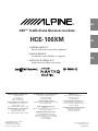
Alpine HCE-100XM User manual
- Category
- Car navigation systems
- Type
- User manual
This manual is also suitable for

IT
SE
EN
FR
ES
R
HCE-100XM
Designed by ALPINE Japan
Printed in Japan (Y)
68-02065Z76-A
XM™ Traffic Data Receiver module
(RCS PONTOISE B 338 101 280)
YAMAGATA Corporation
2-6-34, Takashima, Nishi-Ku,
Yokohama, Kanagawa, Japan
• OWNER'S MANUAL
Please read before using this equipment.
• MODE D'EMPLOI
Veuillez lire avant d’utiliser cet appareil.
• MANUAL DE OPERACIÓN
Léalo antes de utilizar este equipo.
ALPINE ELECTRONICS MARKETING, INC.
1-1-8 Nishi Gotanda,
Shinagawa-ku,
Tokyo 141-0031, Japan
Phone 03-5496-8231
ALPINE ELECTRONICS OF AMERICA, INC.
19145 Gramercy Place, Torrance,
California 90501, U.S.A.
Phone 1-800-ALPINE-1 (1-800-257-4631)
ALPINE ELECTRONICS OF CANADA, INC.
777 Supertest Road, Toronto,
Ontario M3J 2M9, Canada
Phone 1-800-ALPINE-1 (1-800-257-4631)
ALPINE ITALIA S.p.A.
Viale C. Colombo 8, 20090 Trezzano
Sul Naviglio (MI), Italy
Phone 02-484781
ALPINE ELECTRONICS DE ESPAÑA, S.A.
Portal de Gamarra 36, Pabellón, 32
01013 Vitoria (Alava)-APDO 133, Spain
Phone 945-283588
ALPINE ELECTRONICS (BENELUX) GmbH
Leuvensesteenweg 510-B6,
1930 Zaventem, Belgium
Phone 02-725-13 15
ALPINE ELECTRONICS OF AUSTRALIA PTY. LTD.
161-165 Princes Highway, Hallam
Victoria 3803, Australia
Phone 03-8787-1200
ALPINE ELECTRONICS GmbH
Frankfurter Ring 117, 80807 München, Germany
Phone 089-32 42 640
ALPINE ELECTRONICS OF U.K. LTD.
Alpine House
Fletchamstead Highway, Coventry CV4 9TW, U.K.
Phone 0870-33 33 763
ALPINE ELECTRONICS FRANCE S.A.R.L.
(RCS PONTOISE B 338 101 280)
98, Rue de la Belle Etoile, Z.I. Paris Nord Il,
B.P. 50016, 95945 Roissy Charles de Gaulle
Cedex, France
Phone 01-48638989

1-EN
ENGLISH
Contents
Operating Instructions
WARNING
WARNING .................................................. 2
CAUTION ................................................... 3
Getting Started
Receiving XM data broadcasts ......................... 4
Initial System Start-Up ..................................... 4
Checking the XM Receiver ID Number ........... 4
Traffic Information
Traffic Incident List .......................................... 5
Detouring Traffic Congestion ........................ 6
Viewing Traffic Incident Icon Information ....... 6
Weather Forecast ............................................... 6
Setup
Traffic Information............................................ 7
Traffic Icons................................................... 8
Traffic Speed Flow ........................................ 8
Detour Based On ........................................... 9
Reference
If this Message Appears .................................... 9
Specifications .................................................... 9
Installation and Connections
Installation ...................................................... 10
Velcro fastener Mounting ............................ 10
Screw-down Mounting ................................ 10
Connections .................................................... 11

2-EN
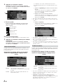
WARNING
WARNING
This symbol means important instructions.
Failure to heed them can result in serious
injury or death.
DO NOT DISASSEMBLE OR ALTER.
Doing so may result in an accident, fire or electric shock.
KEEP SMALL OBJECTS SUCH AS BATTERY OUT OF THE
REACH OF CHILDREN.
Swallowing them may result in serious injury. If swallowed,
consult a physician immediately.
USE ONLY IN CARS WITH A 12 VOLT NEGATIVE GROUND.
(Check with your dealer if you are not sure.) Failure to do so may
result in fire, etc.
BEFORE WIRING, DISCONNECT THE CABLE FROM THE
NEGATIVE BATTERY TERMINAL.
Failure to do so may result in electric shock or injury due to
electrical shorts.
DO NOT SPLICE INTO ELECTRICAL CABLES.
Never cut away cable insulation to supply power to other
equipment. Doing so will exceed the current carrying capacity of
the wire and result in fire or electric shock.
DO NOT DAMAGE PIPE OR WIRING WHEN DRILLING
HOLES.
When drilling holes in the chassis for installation, take
precautions so as not to contact, damage or obstruct pipes, fuel
lines, tanks or electrical wiring. Failure to take such precautions
may result in fire.
DO NOT USE BOLTS OR NUTS IN THE BRAKE OR
STEERING SYSTEMS TO MAKE GROUND CONNECTIONS.
Bolts or nuts used for the brake or steering systems (or any other
safety-related system), or tanks should NEVER be used for
installations or ground connections. Using such parts could
disable control of the vehicle and cause fire etc.
DO NOT ALLOW CABLES TO BECOME ENTANGLED IN
SURROUNDING OBJECTS.
Arrange wiring and cables in compliance with the manual to
prevent obstructions when driving. Cables or wiring that obstruct
or hang up on places such as the steering wheel, shift lever, brake
pedals, etc. can be extremely hazardous.
Operating Instructions
USE THIS PRODUCT FOR MOBILE 12V APPLICATIONS.
Use for other than its designed application may result in fire,
electric shock or other injury.
MAKE THE CORRECT CONNECTIONS.
Failure to make the proper connections may result in fire or product
damage.
USE THE CORRECT AMPERE RATING WHEN REPLACING
FUSES.
Failure to do so may result in fire or electric shock.
DO NOT OPERATE ANY FUNCTION THAT TAKES YOUR
ATTENTION AWAY FROM SAFELY DRIVING YOUR
VEHICLE.
Any function that requires your prolonged attention should only
be performed after coming to a complete stop. Always stop the
vehicle in a safe location before performing these functions.
Failure to do so may result in an accident.
MINIMIZE DISPLAY VIEWING WHILE DRIVING.
Viewing the display may distract the driver from looking ahead of
the vehicle and cause an accident.
DO NOT BLOCK VENTS OR RADIATOR PANELS.
Doing so may cause heat to build up inside and may result in fire.
DO NOT INSTALL IN LOCATIONS WHICH MIGHT HINDER
VEHICLE OPERATION, SUCH AS THE STEERING WHEEL
OR GEARSHIFT.
Doing so may obstruct forward vision or hamper movement etc.
and results in serious accident.
DO NOT FOLLOW ROUTE SUGGESTIONS IF THE
NAVIGATION SYSTEM INSTRUCTS YOU TO PERFORM AN
UNSAFE OR ILLEGAL MANEUVER, OR PLACES YOU IN AN
UNSAFE SITUATION OR AREA.
This product is not a substitute for your personal judgment. Any
route suggestions by this system should never supersede any local
traffic regulations or your personal judgment or knowledge of
safe driving.

3-EN
CAUTION
This symbol means important instructions.
Failure to heed them can result in injury or
material property damage.
USE SPECIFIED ACCESSORY PARTS AND INSTALL THEM
SECURELY.
Be sure to use only the specified accessory parts. Use of other
than designated parts may damage this unit internally or may not
securely install the unit in place. This may cause parts to become
loose resulting in hazards or product failure.
DO NOT INSTALL IN LOCATIONS WITH HIGH MOISTURE
OR DUST.
Avoid installing the unit in locations with high incidence of
moisture or dust. Moisture or dust that penetrates into this unit
may result in product failure.
HAVE THE WIRING AND INSTALLATION DONE BY
EXPERTS.
The wiring and installation of this unit requires special technical
skill and experience. To ensure safety, always contact the dealer
where you purchased this product to have the work done.
ARRANGE THE WIRING SO IT IS NOT CRIMPED OR
PINCHED BY A SHARP METAL EDGE.
Route the cables and wiring away from moving parts (like the
seat rails) or sharp or pointed edges. This will prevent crimping
and damage to the wiring. If wiring passes through a hole in
metal, use a rubber grommet to prevent the wire’s insulation from
being cut by the metal edge of the hole.
HALT USE IMMEDIATELY IF A PROBLEM APPEARS.
Failure to do so may cause personal injury or damage to the
product. Return it to your authorized Alpine dealer or the nearest
Alpine Service Center for repairing.

4-EN
Getting Started
Receiving XM data broadcasts
If this receiver is connected to an XM compatible Alpine
navigation system, Traffic & Weather information can be
received and displayed on the navigation screen. The
operation is controled from the navigation system. For
operating details, refer to the Owner’s Manual of the NVD-
A801 map disc. This unit is compatible with NVE-N872A
DVD-ROM navigation system.
For details about how to view this manual, refer to “Manual
Overview” in the NVD-A801 Owner's Manual.
How to Subscribe
Make sure that the optional XM antenna has been installed
before beginning the subscription process. Users can
subscribe by visiting XM’s Website at
www.xmradio.com
or by calling 1-800-XM-RADIO (1-800-967-2346).
Customers should have their Receiver ID ready; see
“Checking the XM Receiver ID Number” on this page.
•© 2005 XM Satellite Radio Inc. All rights reserved.
•NAVTEQ Traffic- is a trademark of NAVTEQ North
America, LLC.-2005. NAVTEQ North America, LLC.
• XM and its corresponding logos are trademarks of XM
Satellite Radio Inc.
• NavTraffic is the nation's first satellite traffic information
service to display current traffic information for a driver's
chosen route on the vehicle's on-board navigation system.
XM NavTraffic is powered by NAVTEQ Traffic.
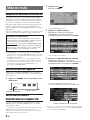
Initial System Start-Up
Be sure to press the RESET switch when using the unit for
the first time, after changing the car battery, etc.
11
Press RESET with a ball-point pen or similar
pointed object.
Checking the XM Receiver ID Number
You need to provide XM with the unique XM Receiver ID
number for your HCE-100XM in order to subscribe to XM's
programming.
This number is an 8 character alphanumeric number
that is printed on a label directly on the bottom of the
unit.
This number is also displayed in the Navigation System
and can be found in the following way.
RESET switch
(Side of the unit)
1
Touch [ ].
Press MENU.
The Nav Menu screen is displayed.
2
Touch [Setup].
Select (highlight) “Setup” by tilting the joystick and
press ENTER.
The Setup menu is displayed.
3
Touch [Traffic Information].
Select (highlight) “Traffic Information” by tilting the
joystick and press ENTER.
The Traffic Information screen is displayed.
The XM Receiver ID number is displayed.
•You can check your ID number printed on the label on the
bottom of the HCE-100XM, or on the label on the packing
box.
XM Receiver ID number
RESET

5-EN
Traffic Information
Traffic Incident List
If you receive Traffic Information, you can display the Traffic
Incident List in order to confirm traffic information enroute to
a destination or on roads in the vicinity of the vehicle.
1
Touch [ ].
Press MENU.
The Nav Menu screen is displayed.
2
Touch [Information].
Select (highlight) “Information” by tilting the joystick
and press ENTER.
The Information menu is displayed.
3
Touch [Traffic Incident List].
Select (highlight) “Traffic Incident List” by tilting
the joystick and press ENTER.
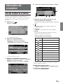
4
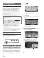
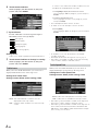
The Traffic Incident List screen is displayed.
a Traffic Incident (Street name and Traffic
Incident Icon)
You can confirm Traffic incident details.
b
A map of the area surrounding the Traffic Incident can
be displayed.
c Legend
Tells you what a particular incident icon represents.
d Detour
You can detour around congestion on your route.
Traffic Incident Icon
•You can display the Traffic Incident List in the following
ways.
Touch Operation:
Touch [Traffic] on the map screen.
Remote Control Operation:
Press TRAFFIC INFO.
Icon
Legend
Accident
Blockage
Construction / Roadworks
Danger
Debris
Disabled Vehicle
Information
Sports Event
Traffic Jam
Weather
c
d
a
b

6-EN
Detouring Traffic Congestion
1
Touch [Detour] on the Traffic Incident List
screen.
Select (highlight) “Detour” by tilting the joystick and
press ENTER.
The system analyzes traffic data reported on the route
within 30 miles of the vehicle's position. If traffic
congestion is found, the system displays a message
with the distance to the congestion, and the
anticipated delay if the congestion is not detoured.
•To use the congestion detour feature, make sure that you
have chosen “Traffic” (see “Detour Based On” on page 9).
2
Touch [Detour].
Select (highlight) “Detour” by tilting the joystick and
press ENTER.
The system begins calculating a new route.
• If you do not want to detour a congested area, select .
Viewing Traffic Incident Icon
Information
When you set Traffic Icons (see page 8) or Traffic Speed
Flow (see page 8) to “Show”, and the Navigation System is
receiving traffic information, Traffic Incident Icons and/or
Traffic Speed Flow will be displayed on the map screen
where reported and available.
a Traffic Incident Icon
b Traffic Speed Flow
Traffic Incident icons and detailed information is available
for all reported incidents.
• It is possible for the detailed information to be identical to
the summary information.
Weather Forecast
If you receive Weather Information, you can confirm the
current weather conditions for the nearest available city to the
vehicle, and 5-Day (Weekly) forecasts for the nearest
available city, or for cities in other States.
•Weather Information may take some time to display.
1
Touch [ ].
Press MENU.
The Nav Menu screen is displayed.
2
Touch [Information].
Select (highlight) “Information” by tilting the joystick
and press ENTER.
The Information menu is displayed.
ab
Red
Yellow
Green
Surface Streets/Freeways
US Units
0-10 mph
10-45 mph
45 mph and above
Metric Units
0-20 km/h
20-90 km/h
90 km/h and above

7-EN
3
Touch [Weather Forecast] on the
Information menu screen.
Select (highlight) “Weather Forecast” by tilting the
joystick and press ENTER.
Displays the Current Conditions for the nearest
available city to the vehicle.
Time when conditions were recorded is displayed.
4
Touch [Weekly Forecast] on the Current
Conditions screen.
Press ENTER (Weekly Forecast).
Displays the 5-Day (Weekly) forecast for the nearest
available city to the vehicle.
a Change
you can choose to view the 5-Day (Weekly) forecast of
several other cities in the U.S.A. After selecting
“Change” select your desired state.
a
Setup
Traffic Information
Can be set only when HCE-100XM is connected.
1
Touch [ ].
Press MENU.
The Nav Menu screen is displayed.
2
Touch [Setup].
Select (highlight) “Setup” by tilting the joystick and
press ENTER.
The Setup menu is displayed.
3
Touch [Traffic Information].
Select (highlight) “Traffic Information” by tilting the
joystick and press ENTER.
The Traffic Information screen is displayed.
Continued

8-EN
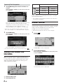
4
Touch the desired item.
Select (highlight) the desired item by tilting the
joystick and press ENTER.
a System Status
If Traffic & Weather is received, signal strength is
indicated by a 4-bar icon type display.
(No Signal)
(Weak Signal)
(Marginal Signal)
(Strong Signal)
(Very Strong Signal)
Setting items:
Traffic Icons / Traffic Speed Flow / Detour Based On
5
Touch the desired Item to change its setting.
Select (highlight) the desired item by tilting the
joystick and press ENTER.
Traffic Icons
When you receive Traffic Information, you can choose to
display Traffic Incident icons on the map screen.
Setting item: Traffic Icons
Setting content: Show (Initial setting) / Hide
Show: The selected Traffic Incident Icons are
displayed on the map screen.
Hide: Clear the Traffic Incident Icons from the map
screen.
If “Show” is set, select which Traffic Incident icons you
would like to see displayed on the map.
1 Touch [Edit] to display the Traffic Icons screen.
Select (highlight) “Edit” by tilting the joystick and press
ENTER.
2 Touch the desired traffic icons.
Select (highlight) the traffic icon by tilting the joystick
and press ENTER.
• Selected Traffic Incident icons are checked.
• If “ALL” is selected, all traffic icons are checked.
3 Touch [Done].
Select (highlight) “Done” by tilting the joystick and press
ENTER.
• If “Default” is selected, all incidents icons shall be
viewable on the map.
•For Traffic Incident Icon descriptions, refer to page 5.
• The traffic icons shall be viewable on the map when map
scale is 5 miles (10 km) to 1/32 mile (50 m).
Traffic Speed Flow
When you receive traffic information, you can choose to
display Traffic Flow (Congestion) on the map screen.
Setting item: Traffic Speed Flow
Setting content: Show (Initial setting) / Hide
Show: Traffic Flow is displayed on the map screen.
Hide:Traffic Flow is cleared from the map screen.
• The traffic speed flow shall be viewable on the map when
map scale is 5 miles (10 km) to 1/32 mile (50 m).
• The traffic speed flow shall be viewable on the map only on
those roads for which the information is broadcasted by
XM. Please contact XM for updated information on traffic
flow coverage for your area.
a

9-EN
Detour Based On
When you select “Detour” in the Traffic Incident List screen
or press the DETOUR key on the remote controller, the
Navigation shall allow you to detour your route based on the
setting you have chosen.
Setting item: Detour Based On
Setting content: Traffic (Initial setting) / Distance
Traffic: The system shall perform a detour by
considering traffic congestion reported
along the route within 30 miles ahead of the
vehicle.
Distance: The system shall perform a detour by
considering distance selected by the User
only.
• At present traffic information is not available for all cities.
Please contact XM for updated information on traffic
coverage for your area.
Reference
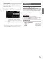
If this Message Appears
Various messages are displayed on the screen during
operation. In addition to the messages telling you the current
status or providing guidance for the next operation, there are
also the following error messages. If one of these error
messages is displayed, carefully follow the instructions in the
solution column.
Check Antenna.
• The XM antenna is not connected to this unit.
- Check whether the XM antenna cable is attached securely to
this unit, then turn the ignition off and on again.
Specifications
External dimensions
Width 160 mm (6-1/4")
Height 40 mm (1-9/16")
Depth 120 mm (4-3/4")
Weight 610 g (1lb 6 oz)

10-EN
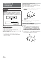
Installation and
Connections
Installation
Caution
Do not block the unit’s air vents. This unit requires
adequate air circulation. If blocked, heat will accumulate
inside the unit and may cause a fire.
Accessory List
• XM data receiver .......................................................... 1
• Power cable .................................................................. 1
• Navigation connection cable (5m) ............................... 1
• XM tuner cable (3m) ..................................................... 1
• Self tapping screw (M4 × 14) ....................................... 4
• Velcro Fasteners .......................................................... 2
• An antenna is required for the proper operation of this
receiver. This antenna must be purchased separately.
Please follow the installation instructions supplied with the
antenna.
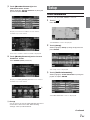
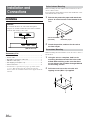
Velcro fastener Mounting
When mounting the unit with the Velcro fasteners, be sure to
choose a flat location.
Do not hang the unit from the bottom of the dashboard or rear
deck with the Velcro fasteners.
1
Remove the protective paper and attach two
pieces of velcro fastener to the bottom of the
unit.
2
Check the position, and then fix the unit to
the floor carpet.
Screw-down Mounting
When mounting the tuner with the screws, be sure to choose a
flat location.
1
Using the unit as a template, hold it at its
mounting location and mark the holes to be
drilled. Before drilling, make sure that there
are no objects that could be damaged behind
the mounting surface.
2
Drill holes and secure the unit with self-
tapping screws (M4 x 14) supplied.
Velcro Fasteners
(Included)
Protective paper
Air vents
(Side of the unit)

11-EN
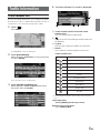
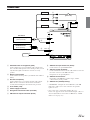
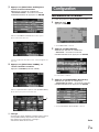
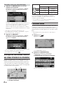
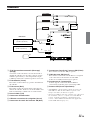
Connections
1 Switched Power Lead (Ignition) (Red)
Connect this lead to an open terminal on the vehicle’s fuse
box or another unused power source which provides (+) 12V
only when the ignition is turned on or in the accessory
position.
2 Battery Lead (Yellow)
Connect this lead to the positive (+) terminal of the vehicle's
battery.
3 Ground Lead (Black)
Connect this lead to a good chassis ground on the vehicle.
Make sure the connection is made to bare metal and is
securely fastened using the sheet metal screw provided.
4 Fuse Holder (7.5A)
5 Power Supply Connector
6 Navigation Connection Cable (Included)
7 XM Antenna Output Connector (Black)
8 XM Antenna Input Connector (Violet)
Connect this to an optional XM antenna.
9 XM Tuner Cable (Included)
Connect the black connector of the cable to this receiver and
the violet connector to the XM radio tuner.
If required, use an optional splitter.*
! XM Antenna Connector
Depending on the XM tuner connector type, antenna
connection may not be possible.
" XM Antenna (Sold Separately)
* “NO SIGNAL” is displayed on the XM tuner if the XM
radio tuner cable is not connected when an optional
splitter is used.
• After connecting, confirm that "Traffic Receiver:
Connected" appears in the System Status display. (Refer to
"System Information" in the Owner's Manual of a NVD-
A801 series on page 57.)
IGNITION
BATTERY
GND
Ignition Key
Battery
NVE-N872A
XM compatible Navigation
XM Radio Tuner
(Sold separately)
(Sold separately)
Violet
Black
2
1
3
4
5
7
8
6
9
!
"
Page is loading ...
Page is loading ...
Page is loading ...
Page is loading ...
Page is loading ...
Page is loading ...
Page is loading ...
Page is loading ...
Page is loading ...
Page is loading ...
Page is loading ...
Page is loading ...
Page is loading ...
Page is loading ...
Page is loading ...
Page is loading ...
Page is loading ...
Page is loading ...
Page is loading ...
Page is loading ...
Page is loading ...
Page is loading ...
-
 1
1
-
 2
2
-
 3
3
-
 4
4
-
 5
5
-
 6
6
-
 7
7
-
 8
8
-
 9
9
-
 10
10
-
 11
11
-
 12
12
-
 13
13
-
 14
14
-
 15
15
-
 16
16
-
 17
17
-
 18
18
-
 19
19
-
 20
20
-
 21
21
-
 22
22
-
 23
23
-
 24
24
-
 25
25
-
 26
26
-
 27
27
-
 28
28
-
 29
29
-
 30
30
-
 31
31
-
 32
32
-
 33
33
-
 34
34


Alpine HCE-100XM User manual
- Category
- Car navigation systems
- Type
- User manual
- This manual is also suitable for
Ask a question and I''ll find the answer in the document
Finding information in a document is now easier with AI
in other languages
- français: Alpine HCE-100XM Manuel utilisateur
Related papers
-
Alpine PMD-B100T - Blackbird - Automotive GPS Receiver User manual
-
-
Alpine 3DE-7985E User manual
-
Alpine HCE-C105 - Rear View Camera System User manual
-
-
-
-
-
Alpine NVE-M300P Owner's manual
-
Other documents
-
Pioneer AVIC F60 DAB Quick start guide
-
Pioneer AVIC-EVO1-G72-QYI Quick start guide
-
Pioneer AVIC EVO1 Quick start guide
-
Honda Accord Hybrid Owner's manual
-
-
Acura 2017 RLX Navigation Manual
-
Honda Crosstour Owner's manual
-
-
-