
INSTRUCTION MANUAL
MANUAL DE INSTRUÇÕES
MANUAL DE INSTRUCCIONES
DW366
7-1/4" (184 mm) Circular Saw
Serra Circular 7-1/4" (184 mm)
Sierra Circular de 184 mm (7-1/4")
INSTRUCTIVO DE OPERACIÓN, CENTROS DE SERVICIO Y PÓLIZA
DE GARANTÍA. ADVERTENCIA: LÉASE ESTE INSTRUCTIVO ANTES
DE USAR EL PRODUCTO.
Questions? See us on the World Wide Web at www.dewalt.com
¿Dudas? Visítenos en Internet: www.dewalt.com
Dúvidas? Visite-nos na Internet em www.dewalt.com.br
Page is loading ...

1
English
Definitions: Safety Guidelines
The definitions below describe the level of severity for each
signal word. Please read the manual and pay attention to these
symbols.
DANGER: Indicates an imminently hazardous situation
which, if not avoided, will result in death or serious injury.
WARNING: Indicates a potentially hazardous situation
which, if not avoided, could result in death or serious injury.
CAUTION: Indicates a potentially hazardous situation which,
if not avoided, may result in minor or moderate injury.
NOTICE: Used without the safety alert symbol indicates a
potentially hazardous situation which, if not avoided, may result
in property damage.
WARNING: To reduce the risk of injury, read the instruction
manual.
General Power Tool Safety Warnings
WARNING! Read all safety warnings and all instructions
Failure to follow the warnings and instructions may result in
electric shock, fire and/or serious injury.
SAVE ALL WARNINGS AND INSTRUCTIONS
FOR FUTURE REFERENCE
The term “power tool” in the warnings refers to your mains-operated
(corded) power tool or battery-operated (cordless) power tool.
1) WORK AREA SAFETY
a) Keep work area clean and well lit. Cluttered or dark areas
invite accidents.
b) Do not operate power tools in explosive atmospheres, such
as in the presence of flammable liquids, gases or dust.
Power tools create sparks which may ignite the dust or fumes.
c) Keep children and bystanders away while operating a
power tool. Distractions can cause you to lose control.
2) ELECTRICAL SAFETY
a) Power tool plugs must match the outlet. Never modify the
plug in any way. Do not use any adapter plugs with earthed
(grounded) power tools. Unmodified plugs and matching
outlets will reduce risk of electric shock.
b) Avoid body contact with earthed or grounded surfaces
such as pipes, radiators, ranges and refrigerators. There
is an increased risk of electric shock if your body is earthed or
grounded.
c) Do not expose power tools to rain or wet conditions. Water
entering a power tool will increase the risk of electric shock.
d) Do not abuse the cord. Never use the cord for carrying,
pulling or unplugging the power tool. Keep cord away
from heat, oil, sharp edges or moving parts. Damaged or
entangled cords increase the risk of electric shock.
e) When operating a power tool outdoors, use an extension
cord suitable for outdoor use. Use of a cord suitable for
outdoor use reduces the risk of electric shock.
f) If operating a power tool in a damp location is unavoidable,
use a residual current device (GFCI) protected supply. Use
of an GFCI reduces the risk of electric shock.
3) PERSONAL SAFETY
a) Stay alert, watch what you are doing and use common
sense when operating a power tool. Do not use a power tool
while you are tired or under the influence of drugs, alcohol
or medication. A moment of inattention while operating power
tools may result in serious personal injury.
b) Use personal protective equipment. Always wear eye
protection. Protective equipment such as dust mask, non-
skid safety shoes, hard hat, or hearing protection used for
appropriate conditions will reduce personal injuries.

2
English
c) Prevent unintentional starting. Ensure the switch is in the
off position before connecting to power source and/or
battery pack, picking up or carrying the tool. Carrying power
tools with your finger on the switch or energising power tools that
have the switch on invites accidents.
d) Remove any adjusting key or wrench before turning the
power tool on. A wrench or a key left attached to a rotating part
of the power tool may result in personal injury.
e) Do not overreach. Keep proper footing and balance at
all times. This enables better control of the power tool in
unexpected situations.
f) Dress properly. Do not wear loose clothing or jewellery.
Keep your hair, clothing and gloves away from moving
parts. Loose clothes, jewellery or long hair can be caught in
moving parts.
g) If devices are provided for the connection of dust extraction
and collection facilities, ensure these are connected and
properly used. Use of dust collection can reduce dust-related
hazards.
4) POWER TOOL USE AND CARE
a) Do not force the power tool. Use the correct power tool for
your application. The correct power tool will do the job better
and safer at the rate for which it was designed.
b) Do not use the power tool if the switch does not turn it on
and off. Any power tool that cannot be controlled with the switch
is dangerous and must be repaired.
c) Disconnect the plug from the power source and/or the
battery pack from the power tool before making any
adjustments, changing accessories, or storing power tools.
Such preventive safety measures reduce the risk of starting the
power tool accidentally.
d) Store idle power tools out of the reach of children and do
not allow persons unfamiliar with the power tool or these
instructions to operate the power tool. Power tools are
dangerous in the hands of untrained users.
e) Maintain power tools. Check for misalignment or binding
of moving parts, breakage of parts and any other condition
that may affect the power tool’s operation. If damaged,
have the power tool repaired before use. Many accidents are
caused by poorly maintained power tools.
f) Keep cutting tools sharp and clean. Properly maintained
cutting tools with sharp cutting edges are less likely to bind and
are easier to control.
g) Use the power tool, accessories and tool bits etc., in
accordance with these instructions taking into account the
working conditions and the work to be performed. Use of
the power tool for operations different from those intended could
result in a hazardous situation.
5) SERVICE
a) Have your power tool serviced by a qualified repair person
using only identical replacement parts. This will ensure that
the safety of the power tool is maintained.
Additional Safety Instructions for
Circular Saws
DANGER! Keep hands away from cutting area and blade. Keep
your second hand on auxiliary handle, or motor housing. If both
hands are holding the saw, they cannot be cut by the blade.
• Keep your body positioned to either side of the saw blade, but
not in line with the saw blade. KICKBACK could case the saw to
jump backwards. (See “Causes and Operator Prevention of Kickback,
page 3 and ”KICKBACK” page 8)
• Do not reach underneath the work. The guard can not protect
you from the blade below the work.
• Check lower guard for proper closing before each use. Do not
operate saw if lower guard does not move freely and close
instantly. Never clamp or tie the lower guard into the open

3
English
position. If saw is accidentally dropped, the lower guard may be
bent. Raise the lower guard with the Retracting Handle and make
sure it moves freely and does not touch the blade or any other part,
at all angles and depth of cut.
• Check the operation and condition of the lower guard spring.
If the guard and the spring are not operating properly,
they must be serviced before use. Lower guard may operate
sluggishly due to damaged parts, gummy deposits, or a buildup of
debris.
• Lower guard should be retracted manually only for special
cuts such as “Pocket Cuts” and “Compound Cuts.” Raise
lower guard by Retracting Handle. As soon as blade enters
the material, lower guard must be released. For all other
sawing, the lower guard should operate automatically.
• Always observe that the lower guard is covering the blade
before placing saw down on bench or floor. An unprotected,
coasting blade will cause the saw to walk backwards, cutting
whatever is in its path. Be aware of the time it takes for the blade
to stop after switch is released.
• NEVER hold piece being cut in your hands or across your
leg. It is important to support the work properly to minimize body
exposure, blade binding, or loss of control.
• Hold tool by insulated gripping surfaces when performing an
operation where the cutting tool may contact hidden wiring
or its own cord. Contact with a “live” wire will also make exposed
metal parts of the tool “live” and shock the operator.
• When ripping, always use a rip fence or straight edge guide.
This improves the accuracy of cut and reduces the chance for
blade binding.
• Always use blades with correct size and shape (diamond
vs. round) arbor holes. Blades that do not match the mounting
hardware of the saw will run eccentrically, causing loss of control.
• Never use damaged or incorrect blade washers or bolts. The
blade washers and bolt were specially designed for your saw, for
optimum performance and safety of operation.
CAUSES AND OPERATOR PREVENTION OF KICKBACK
• Kickback is a sudden reaction to a pinched, bound or misaligned
saw blade, causing an uncontrolled saw to lift up and out of the
workpiece toward the operator.
• When the blade is pinched or bound tightly by the kerf closing
down, the blade stalls and the motor reaction drives the unit rapidly
back toward the operator.
• If the blade becomes twisted or misaligned in the cut, the teeth at
the back edge of the blade can dig into the top surface of the wood
causing the blade to climb out of the kerf and jump back toward
operator.
• Kickback is the result of tool misuse and/or incorrect operating
procedures or conditions and can be avoided by taking proper
precautions as given below.
a. Maintain a firm grip with both hands on the saw and position
your body and arm to allow you to resist KICKBACK forces.
Kickback forces can be controlled by the operator, if proper
precautions are taken.
b. When blade is binding, or when interrupting a cut for any
reason, release the trigger and hold the saw motionless in
the material into the blade comes to a complete stop. Never
attempt to remove the saw from the work or pull the saw
backward while the blade is in motion or KICKBACK may
occur. Investigate and take corrective actions to eliminate the
cause of blade binding.
c. When restarting a saw in the workpiece, center the saw
blade in the kerf and check that the saw teeth are not
engaged into the material. If saw blade is binding, it may walk
up or KICKBACK from the workpiece as the saw is restarted.
d. Support large panels to minimize the risk of blade pinching
and KICKBACK. Large panels tend to sag under their own
weight. Support must be placed under the panel on both sides,
near the line of cut and near the edge of the panel.

4
English
e. Do not use dull or damaged blade. Unsharpened or improperly
set blades produce narrow kerf causing excessive friction, blade
binding, and KICKBACK.
f. Blade depth and bevel adjusting locking levers must be
tight and secure before making cut. If blade adjustment shifts
while cutting, it may cause binding and KICKBACK.
g. Use extra caution when making a “Pocket Cut” into existing
walls or other blind areas. The protruding blade may cut
objects that can cause KICKBACK.
Additional Specific Instructions
CAUTION: When cutting into walls, floors or wherever live electrical
wires may be encountered, DO NOT TOUCH ANY METAL PARTS
OF THE TOOL! Hold the tool only by insulated grasping surfaces to
prevent electric shock if you cut into a live wire.
• KEEP BLADES CLEAN AND SHARP. Sharp blades minimize
stalling and kickback.
DANGER: KEEP HANDS AWAY FROM CUTTING AREA. Keep
hands away from blades. Do not reach underneath work while blade
is rotating. Do not attempt to remove cut material when blade is
moving.
CAUTION: Blades coast after turn off.
• SUPPORT LARGE PANELS. Large panels must be supported
as shown in Figure 10 to minimize the risk of blade pinching and
kickback. When cutting operation requires the resting of the saw
on the work piece, the saw shall be rested on the larger portion and
the smaller piece cut off.
• GUARD AGAINST KICKBACK. Kickback occurs when the saw
stalls rapidly and is driven back towards the operator. Release
switch immediately if blade binds or saw stalls. Keep blades sharp.
Support large panels as shown in Figure 10. Use fence or straight
edge guide when ripping. Don’t force tool. Stay alert-exercise
control. Don’t remove saw from work during a cut while the blade
is moving.
• ADJUSTMENTS. Before cutting be sure depth and bevel
adjustments are tight.
• AVOID CUTTING NAILS. Inspect for and remove all nails from
lumber before cutting.
• NEVER use abrasive cut-off wheels.
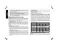
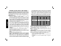
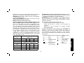
• An extension cord must have adequate wire size (AWG
or American Wire Gauge) for safety. The smaller the gauge
number of the wire, the greater the capacity of the cable, that is
16 gauge has more capacity than 18 gauge. An undersized cord
will cause a drop in line voltage resulting in loss of power and
overheating. When using more than one extension to make up the
total length, be sure each individual extension contains at least the
minimum wire size. The following table shows the correct size to
use depending on cord length and nameplate ampere rating. If in
doubt, use the next heavier gauge. The smaller the gauge number,
the heavier the cord.
Voltage (Volts) Total length of cord in meters (m)
120 - 127V 0 - 7 7 - 15 15 - 30 30 - 50
220 - 240V 0 - 15 15 - 30 30 - 60 60 - 100
Rated Ampere
range
Minimal cross-sectional area of the
cord in meters (mm
2
)
0 - 6A 1.0 1.5 1.5 2.5
6 - 10A 1.0 1.5 2.5 4.0
10 - 12A 1.5 1.5 2.5 4.0
12 - 16A 2.5 4.0 Not Recommended
WARNING: Always use eye protection. All users and bystanders
must wear eye protection that conforms to ANSI Z87.1.
WARNING: Some dust created by power sanding, sawing, grinding,
drilling, and other construction activities contains chemicals known to

5
English
cause cancer, birth defects or other reproductive harm. Some
examples of these chemicals are:
• lead from lead-based paints,
• crystalline silica from bricks and cement and other masonry
products, and
• arsenic and chromium from chemically-treated lumber (CCA).
Your risk from these exposures varies, depending on how often you
do this type of work. To reduce your exposure to these chemicals:
work in a well ventilated area, and work with approved safety
equipment, such as those dust masks that are specially designed to
filter out microscopic particles.
• The label on your tool may include the following symbols.
V .................. volts A ................ amperes
Hz ................ hertz W ............... watts
min ..............minutes
.............. alternating current
................alternating or .......... direct current
....................direct current
n
o .............. no load speed
................
Class II …/min .........revolutions or
..................... Construction ...................reciprocation per
.................earthing terminal ...................minutes
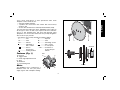
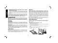
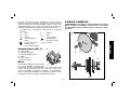
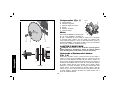
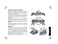
Features (Fig. 1)
B
C
A
D
E
FIG. 1
F
A. End cap
B. Trigger switch
C. Bevel angle adjustment knob
D. Shoe
E. Blade bolt
F. Lower blade guard
Motor
Your DEWALT tool is powered by a
D
EWALT motor. Be sure your power
supply agrees with name plate marking.
E
H
G
SPINDLE
BLADE
FIG. 2
G
E
H

6
English
As little as 10% lower voltage can cause loss of power and can result
in overheating. All D
EWALT tools are factory-tested; if this tool does
not operate, check the power supply.
ADJUSTMENTS AND SETUP
WARNING: To reduce the risk of serious personal injury,
turn tool off and disconnect tool from power source before
making any adjustments or removing/installing attachments or
accessories.
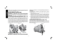
Attaching And Removing Blades (Fig. 1–4)
To attach the blade, retract lower blade guard (F) and place inner
clamp washer (G) and blade on saw spindle with printed side of
blade out. [Teeth at bottom of blade pointing forward, Fig. 2]. Place
outer clamp washer (H) on saw spindle. The larger surfaces of both
washers must face the blade. Thread on blade clamping bolt (E) firmly
by hand to hold both blade washers in position. Depress the lock pin
(I, Fig. 3) and turn the saw spindle until lock pin engages the shaft.
Tighten blade bolt clockwise with blade wrench.
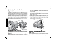
FIG. 4FIG. 3
I
Changing Blades (Fig. 1–4)
WARNING: To reduce the risk of serious personal injury,
turn tool off and disconnect tool from power source before
making any adjustments or removing/installing attachments or
accessories.
Your D
EWALT saw is equipped to accept blades with 5/8" (16 mm)
round arbor holes.
1. Depress LOCK PIN, (I, Fig. 3) and turn blade until the LOCK PIN
locks firmly into the saw shaft.
2. With blade wrench, loosen and remove the blade bolt (E) by
turning it in a counterclockwise direction when facing blade (right
hand thread). Retract lower blade guard (F) and remove blade.
3. When mounting new blade, the teeth must point in the direction
of blade rotation. Replace outer clamp washer (H). Replace and
tighten the blade bolt as much as possible with the fingers, then
tighten firmly with the blade wrench.
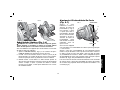
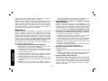
Cutting Depth Adjustment (Fig. 5–7)
Hold the saw firmly. Raise the depth adjustment lever (J, Fig. 5) to
loosen and move shoe to obtain the desired depth of cut, as shown.
Make sure the depth adjustment lever has been retightened (lowered)
before operating saw.
FIG. 5
J
LOOSEN
TIGHTEN
K

7
English
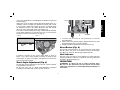
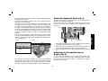
FIG. 8
C
L
TIGHTEN
LOOSEN
1. To set the saw for a bevel cut, turn the knob (C) to loosen the
bevel adjustment.
2. Tilt the shoe to the desired angle by aligning the pointer (L) with
the desired angle mark on the pivot bracket.
3. Retighten the bevel adjustment by turning the knob (C).
Bevel Detent (Fig. 8)
The saw has a bevel stop at 45º. To set the bevel at an angle greater
than 45º, tilt the shoe to 45º, then slide the knob (C) into the upper
slot. When you reach the desired angle, tighten the knob.
Kerf Indicator
The front of the saw shoe has a kerf indicator for vertical and bevel
cutting. This indicator enables you to guide the saw along cutting lines
penciled on the material being cut.
OPERATION
WARNING: To reduce the risk of serious personal injury,
turn tool off and disconnect tool from power source before
making any adjustments or removing/installing attachments or
accessories.
Your saw is equipped with a carbide tipped saw blade for long life and
efficient cutting.
Setting the saw at the proper cutting depth keeps blade friction to a
minimum, removes sawdust from between the blade teeth, results
in cooler, faster sawing and reduces the chance of kickback. Align
the appropriate mark on the depth adjustment strap with triangle
(K, Fig. 5) on the upper blade guard. Your depth is set.
For the most efficient cutting action using a carbide tipped saw blade,
set the depth adjustment so that about one half of a tooth projects
below the surface of the wood to be cut (Fig. 6).
FIG. 6
FIG. 7
A method of checking for the correct cutting depth is shown in
Figure 7. Lay a piece of the material you plan to cut along the side
of the blade, as shown in the figure, and observe how much tooth
projects beyond the material.
Bevel Angle Adjustment (Fig. 8)
The full range of bevel adjustment is from 0 to 50º. The pivot bracket
is graduated in increments of 1º.
On the front of the saw is a bevel angle adjustment mechanism
consisting of a quadrant with a pointer (L) and a knob (C).

8
English
Switch
Pull the trigger switch to turn the motor ON. Releasing the trigger
turns the motor OFF. This tool has no provision to lock the switch in
the ON position, and should never be locked ON in any way.
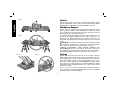
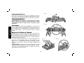
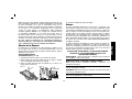
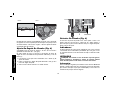
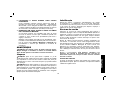
Workpiece Support
Figures 9 and 11 show proper sawing position. Figures 10 and 12
show an unsafe condition. Hands should be kept away from cutting
area, and power cord is positioned clear of the cutting area so that it
will not get caught or hung up on the work.
To avoid kickback, DO support board or panel NEAR the cut,
(Figures 9, 11). DON’T support board or panel away from the cut
(Figures 10, 12). When operating the saw, keep the cord away from
the cutting area and prevent it from becoming hung up on the work
piece.
WARNING: It is important to support the work properly and to hold
the saw firmly to prevent loss of control which could cause personal
injury; Figure 11 illustrates typical hand support of the saw.
ALWAYS DISCONNECT SAW BEFORE MAKING ANY
ADJUST MENTS! Place the work with its “good” side - the one on
which appearance is most important - down. The saw cuts upward, so
any splintering will be on the work face that is up when you saw it.
Cutting
Support the work so that the waste will be on your right. Place the
wider portion of the saw shoe on that part of the work piece which is
solidly supported, not on the section that will fall off when the cut is
made. As examples, Figure 11 illustrates the RIGHT way to cut off
the end of a board, and Figure 12 the WRONG way. Always clamp
work. Don’t try to hold short pieces by hand! Remember to support
cantilevered and overhanging material. Use caution when sawing
material from below.
Be sure saw is up to full speed before blade contacts material to
be cut. Starting saw with blade against material to be cut or pushed
forward into kerf can result in kickback.
FIG. 11
FIG. 10
FIG. 9
FIG. 12

9
English
2. IMPROPER DEPTH OF CUT SETTING ON SAW
Using the saw with an excessive depth of cut setting increases
loading on the unit and susceptibility to twisting of the blade in the
kerf. It also increases the surface area of the blade available for
pinching under conditions of kerf close down. See page 4 Cutting
Depth Adjustment.
3. BLADE TWISTING (MISALIGNMENT IN CUT)
A. Pushing harder to cut through a knot, a nail, or a hard grain
area can cause the blade to twist.
B. Trying to turn the saw in the cut (trying to get back on the
marked line) can cause blade twist
C. Extended reach or operating saw with poor body control (out of
balance), can result in twisting the blade.
D. Changing hand grip or body position while cutting can result in
blade twist.
E. Backing unit up to clear blade can lead to twist if not done care-
fully.
4. MATERIALS THAT REQUIRE EXTRA ATTENTION
A. Wet lumber
B. Green lumber (material freshly cut or not kiln dried)
C. Pressure treated lumber (material treated with preservatives or
anti-rot chemicals)
5. USE OF DULL OR DIRTY BLADES
Dull blades cause increased loading of the saw. To compensate,
an operator will usually push harder which further loads the unit
and promotes twisting of the blade in the kerf. Worn blades may
also have insufficient body clearance which increases the chance
of binding and increased loading.
6. LIFTING THE SAW WHEN MAKING BEVEL CUTS
Bevel cuts require special operator attention to proper cutting
techniques - especially guidance of the saw. Both blade angle to
the shoe and greater blade surface in the material increase the
chance for binding and misalignment (twist) to occur.
Push the saw forward at a speed which allows the blade to cut without
laboring. Hardness and toughness can vary even in the same piece
of material, and knotty or damp sections can put a heavy load on the
saw. When this happens, push the saw more slowly, but hard enough
to keep it working without much decrease in speed.
Kickback
When the saw blade becomes pinched or twisted in the cut, kickback
can occur. The saw is thrust rapidly back toward the operator. When
the blade is pinched or bound tightly by the kerf closing down, the
blade stalls and the motor reaction drives the unit backward. When
the blade becomes twisted or misaligned in the cut, the teeth at the
back edge of the blade can dig into the top surface of the wood
causing the blade to climb out of the kerf and jump back toward the
operator.
Kickback is more likely to occur when any of the following conditions
exist.
1. IMPROPER WORKPIECE SUPPORT
A. Sagging or improper lifting of the cut off piece causing pinching
of the blade (Figure 10).
B. Cutting through material supported at the outer ends only. As
the material weakens it sags, closing down the kerf and pinch-
ing the blade.
C. Cutting off a cantilevered or overhanging piece of material from
the bottom up in a vertical direction. The falling cut off piece can
pinch the blade.
D. Cutting off long narrow strips (as in ripping). The cut off strip
can sag or twist closing the kerf and pinching the blade.
E. Snagging the lower guard on a surface below the material
being cut momentarily reducing operator control. The saw can
lift partially out of the cut increasing the chance of blade twist.

10
English
Brushes
Inspect carbon brushes regularly by unplugging tool, removing the
End Cap (Detail Page 5) and withdrawing the brush assembly. Keep
brushes clean and sliding freely in their guides. Always replace a used
brush in the same orientation in the holder as it was prior to removal.
Carbon brushes have varying symbols stamped into their sides, and
if either brush is worn down to the line closest to the spring, they
must be replaced. Use only identical D
EWALT brushes. New brush
assemblies are available at your local service center. The tool should
be allowed to “run in” (run at no load without a blade) for 5 minutes
before use to seat new brushes.
While “running in” DO NOT TIE, TAPE, OR OTHERWISE LOCK THE
TRIGGER SWITCH ON. HOLD BY HAND ONLY.
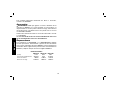
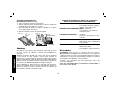
Shoe Adjustment
Your shoe has been factory set to assure that the blade is perpen-
dicular to the shoe. If after extended use, you need to re-align the
blade as follows:
ADJUSTING FOR 90º CUTS (FIG. 8, 13, 14)
1. Return the saw to 0º bevel.
2. Loosen the bevel adjustment knob (C, Fig. 8). Place a square (M)
against the blade and the shoe.
3. Adjust screw (O) until pointer (L) aligns with 0°, then tighten nut
(P).
4. Retighten the bevel adjust knob (C).
TIGHTEN
LOOSEN
FIG. 13
M
FIG. 14
L
O
P
7. RESTARTING A CUT WITH THE BLADE TEETH JAMMED
AGAINST THE MATERIAL
The saw should be brought up to full operating speed before
starting a cut or restarting a cut after the unit has been stopped
with the blade in the kerf. Failure to do so can cause stalling and
kickback.
Any other conditions which could result in pinching, binding, twisting,
or misalignment of the blade could cause kickback. Refer to the
sections on Adjustments And Set-Up and Operation for procedures
and techniques that will minimize the occurrence of kickback.
MAINTENANCE
WARNING: To reduce the risk of serious personal injury,
turn tool off and disconnect tool from power source before
making any adjustments or removing/installing attachments or
accessories.
Cleaning
WARNING: Blow dirt and dust out of the main housing with dry air
as often as dirt is seen collecting in and around the air vents. Wear
approved eye protection and approved dust mask when performing
this procedure.
WARNING: Never use solvents or other harsh chemicals for
cleaning the non-metallic parts of the tool. These chemicals may
weaken the materials used in these parts. Use a cloth dampened only
with water and mild soap. Never let any liquid get inside the tool; never
immerse any part of the tool into a liquid.
Lubrication
Self lubricating ball and roller bearings are used in the tool and
relubrication is not required. However, it is recommended that, once
a year, you take or send the tool to a service center for a thorough
cleaning, inspection and lubrication of the gear case.

11
English
Blades
A dull blade will cause slow, inefficient cutting, overload on the saw
motor, excessive splintering and increase the possibility of kickback.
Change blades when it is no longer easy to push the saw through
the cut, when the motor is straining, or when excessive heat is built
up in the blade. It is a good practice to keep extra blades on hand so
that sharp blades are available for immediate use. Dull blades can be
sharpened in most areas; see SAWS-SHARPENING in the yellow
pages.
Hardened gum on the blade can be removed with kerosene,
turpentine, or oven cleaner. Anti-stick coated blades can be used
in applications where excessive build-up is encountered, such as
pressure treated and green lumber.
VISUALLY EXAMINE CARBIDE BLADES BEFORE USE.
REPLACE IF DAMAGED.
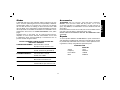
COMBINATION FRAMING - 5/8" Round arbor, 24 teeth
All purpose fast rip and cross cuts.
PRESSURE TREATED/WET LUMBER - 5/8" Round arbor, 20 teeth
Coated - Resistant to gum build-up
EXTREME DURABILITY - 5/8" Round arbor, 18 teeth
Cooled, rock carbide
FINISHING - 5/8" Round arbor, 36 teeth
More teeth for finer finish cuts.
FAST CUT FRAMING - 5/8" Round arbor, 16 teeth
Fastest blade for rips and cross cuts
Accessories
WARNING: Since accessories, other than those offered by
D
EWALT, have not been tested with this product, use of such
accessories with this tool could be hazardous. To reduce the risk of
injury, only D
EWALT, recommended accessories should be used with
this product.
Recommended accessories for use with your tool are available at extra
cost from your local dealer or authorized service center.
WATER FEED ATTACHMENTS ARE NOT RECOMMENDED FOR
THIS SAW.
Repairs
To assure product SAFETY and RELIABILITY, repairs, maintenance
and adjustment (including brush inspection and replacement) should
be performed by authorized service centers or other qualified service
organizations, always using identical replacement parts.
SPECIFICATIONS
DW366-B3
Voltage 120 V
Frequency 50–60 Hz
Power–Watts 1 800 W
RPM 5 800/min
Page is loading ...
Page is loading ...
Page is loading ...
Page is loading ...
Page is loading ...
Page is loading ...
Page is loading ...
Page is loading ...
Page is loading ...
Page is loading ...
Page is loading ...
Page is loading ...
Page is loading ...
Page is loading ...
Page is loading ...
Page is loading ...
Page is loading ...
Page is loading ...
Page is loading ...
Page is loading ...
Page is loading ...
Page is loading ...
Page is loading ...
Page is loading ...
Page is loading ...
Page is loading ...

DEWALT Industrial Tool Co., 701 East Joppa Road, Baltimore, MD 21286 (JAN10) Part # No. N051763 DW366
Copyright © 2010 DEWALT
The following are trademarks for one or more DEWALT power tools: the yellow and black color scheme; the “D” shaped air intake grill; the array
of pyramids on the handgrip; the kit box configuration; and the array of lozenge-shaped humps on the surface of the tool.
HECHO EN CHINA
FABRICADO NA CHINA
MADE IN CHINA
SOLAMENTE PARA PROPÓSITO DE ARGENTINA:
IMPORTADO POR: BLACK & DECKER ARGENTINA S.A.
PACHECO TRADE CENTER
COLECTORA ESTE DE RUTA PANAMERICANA
KM. 32.0 EL TALAR DE PACHECO
PARTIDO DE TIGRE
BUENOS AIRES (B1618FBQ)
REPÚBLICA DE ARGENTINA
NO. DE IMPORTADOR: 1146/66
TEL. (011) 4726-4400
IMPORTED BY/IMPORTADO POR:
BLACK & DECKER DO BRASIL LTDA.
ROD. BR 050, S/N° - KM 167
DIST. INDUSTRIAL II
UBERABA – MG – CEP: 38064-750
CNPJ: 53.296.273/0001-91
INSC. EST.: 701.948.711.00-98
S.A.C.: 0800-703-4644
SOLAMENTE PARA PROPÓSITO DE MÉXICO:
IMPORTADO POR: BLACK & DECKER S.A. DE C.V.
BOSQUES DE CIDROS, ACCESO RADIATAS NO. 42
3A. SECCIÓN DE BOSQUES DE LAS LOMAS
DELEGACIÓN CUAJIMALPA,
05120, MÉXICO, D.F.
TEL. (52) 555-326-7100
R.F.C.: BDE810626-1W7
MAQUINAS Y HERRAMIENTAS BLACK & DECKER CHILE S.A.
AVDA. EDUARDO FREI M. #6001 EDIFICIO 67
CONCHALI-SANTIAGO
CHILE
-
 1
1
-
 2
2
-
 3
3
-
 4
4
-
 5
5
-
 6
6
-
 7
7
-
 8
8
-
 9
9
-
 10
10
-
 11
11
-
 12
12
-
 13
13
-
 14
14
-
 15
15
-
 16
16
-
 17
17
-
 18
18
-
 19
19
-
 20
20
-
 21
21
-
 22
22
-
 23
23
-
 24
24
-
 25
25
-
 26
26
-
 27
27
-
 28
28
-
 29
29
-
 30
30
-
 31
31
-
 32
32
-
 33
33
-
 34
34
-
 35
35
-
 36
36
-
 37
37
-
 38
38
-
 39
39
-
 40
40


Ask a question and I''ll find the answer in the document
Finding information in a document is now easier with AI
in other languages
- español: DeWalt DW366 Manual de usuario
- português: DeWalt DW366 Manual do usuário
Related papers
Other documents
-
Craftsman CMES500 Owner's manual
-
Milwaukee M18 CCS55 User manual
-
Milwaukee 6394 User manual
-
Milwaukee HD28MS User manual
-
Milwaukee 6470-21 User manual
-
Black & Decker CS1500 User manual
-
-
-
RIDGID R3203-1 User manual
-