Thermaltake 01THV85540001 User manual
- Category
- Computer cases
- Type
- User manual
This manual is also suitable for

VJ8000 Series
Tested To Comply
With FCC Standards
FOR HOME OR OFFICE USE
2009 Thermaltake Technology Co., Ltd. All Rights Reserved. 2009.01
C
All other registered trademarks belong to their respective companies.
www.thermaltake.com
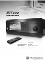
DH 202
User's Manual
Benutzerhandbuch
Mode d’emploi
Manual del usuario
Manuale dell’utente
安裝說明書
用戶手冊
ユーザーズマニュアル
Руководство пользователя
kullanıcı elkitabı
Page is loading ...

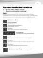
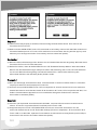
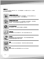
Contens
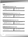
Chapter1 Product Introduction
1.1 Specification
Chapter 2 Case Mechanical Operation
2.2 Power Supply Unit (PSU) Installation
2.1 Top Cover Disassembly
2.3 5.25” Device Installation
2.4 3.5" HDD Installation
2.5 PCI Card Installation
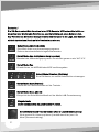
Chapter3 Motherboard & Leads Installation
3.1 Motherboard Installation
3.2 Case LED connections
3.3 USB2.0 & IEEE1394 Firewire connection
3.4 Audio connection
3.5 Case open alarm function ( Intrusion switch )
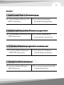
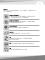
Chapter4 Front Buttons Instruction
4.1 Media LAB Hot keys Module
function instruction:(Optional)
Chapter 5 DH202 Media Kits Quick Guide
5.1 IR Remote Controller Features
5.3 Installation Process
5.2 Media LAB Kit Item List
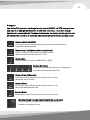
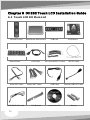
Chapter 6 DH202 Touch LCD Installation Guide
6.1 Touch LCD Kit Item List
6.2 Installation process
6.2.1 Touch LCD Hardware Installation
6.2.2 Dual Monitor Setting for FrontView
6.2.3 Media LAB / iMEDIAN Software Installation
6.3 IR Remote Controller Features
6.4 Using Media LAB / iMEDIAN
6.4.1 iMEDIAN
6.4.2 iMON Manager
6.5 Using frontview
6.6 FrontView introduction
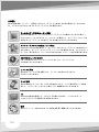
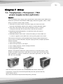
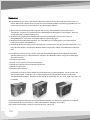
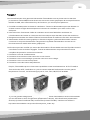
7.1 Toughpower / Purepower / TR2
power supply series (optional)
Chapter 7 Other
1
2
3
4
10
12
14
18
23
25
28
30
40
50
51
75
76
82
97
106
116
126
136
144
154

Contens
Chapter1 Product Introduction
1.1 Specification
Chapter 2 Case Mechanical Operation
2.2 Power Supply Unit (PSU) Installation
2.1 Top Cover Disassembly
2.3 5.25” Device Installation
2.4 3.5" HDD Installation
2.5 PCI Card Installation
Chapter3 Motherboard & Leads Installation
3.1 Motherboard Installation
3.2 Case LED connections
3.3 USB2.0 & IEEE1394 Firewire connection
3.4 Audio connection
3.5 Case open alarm function ( Intrusion switch )
Chapter4 Front Buttons Instruction
4.1 Media LAB Hot keys Module
function instruction:(Optional)
Chapter 5 DH202 Media Kits Quick Guide
5.1 IR Remote Controller Features
5.3 Installation Process
5.2 Media LAB Kit Item List
Chapter 6 DH202 Touch LCD Installation Guide
6.1 Touch LCD Kit Item List
6.2 Installation process
6.2.1 Touch LCD Hardware Installation
6.2.2 Dual Monitor Setting for FrontView
6.2.3 Media LAB / iMEDIAN Software Installation
6.3 IR Remote Controller Features
6.4 Using Media LAB / iMEDIAN
6.4.1 iMEDIAN
6.4.2 iMON Manager
6.5 Using frontview
6.6 FrontView introduction
7.1 Toughpower / Purepower / TR2
power supply series (optional)
Chapter 7 Other
1
2
3
4
10
12
14
18
23
25
28
30
40
50
51
75
76
82
97
106
116
126
136
144
154

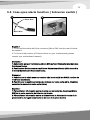
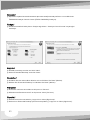
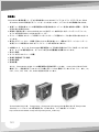
Chapter 2 Case Mechanical Operation
2.1 Top Cover Disassembly
Chapter1 Product Introduction
1.1 Specification
English /
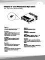
top cover off from the chassis.
Deutsche /
Lösen Sie die Flügelschrauben und
schieben Sie die obere Abdeckung
des Gehäuses an die Seite.
Français /
Dévissez les vis papillons et faites
glisser le couvercle de dessus du
châssis.
Español /
Desatornille los tornillos de mano y
retire la tapa superior del chasis.
Italiano /
Svitare le viti ad aletta e fare scorrere
il coperchio superiore fuori dallo
chassis.
Unscrew thumbscrews and slide the
繁體中文 /
鬆開拇指螺絲並從機殼滑下頂蓋。
简体中文 /
拧松蝶形螺丝,将顶盖滑离机箱。
日本語 /
蝶ねじを抜き、上面カバーをシャーシ
からスライドさせながら外します。
Русский /
Отверните винты с накатанной голо
вкой и снимите верхнюю крышку с ко
рпуса.
Türkçe /
Elle sıkılan vidaları sökün ve üst kapağı
kaydırarak kasadan çıkarın.
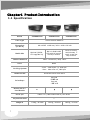
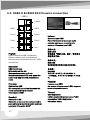
7.85 kg / 17.31l b7.45 kg / 16. 42l b7.42kg / 16. 36l bWeigh ts
7Expan si on Slots
USB 2.0 x 2, IEEE 1394 Firewi re , HD- Au di oFro nt I/O
x
Built-in 23 in 1
Card Reader
Ext er nal
- 5.25 x 1- 5.25" x 1
Int er nal
- 3.5 x 3- 3.5" x 3
Drive Bays
ATX & Micr o ATX for m fact orMothe rbo ard
- Front : 120m m fan x 1, 1500 rpm
- Rear : 60m m fan x 2, 1800 rpm
Cooling Sys tem
Bl ackColor
Panel : Al um inum / Body :SEC CChas si s Mate ri al
Bui lt- in al l new
revol uti onary 7"
touch scr een hot
keys modul e
Bui lt - in Medi a LAB
LCD with 10 butt ons
hot keys modul e
Opti onal (A2430-
LCD upg rade ki t)
Media kits
440 x 426.5 x 168 mm / 18. 1 x 16. 8 x 6. 6 inch
Dimen si on
(D*W*H)
Home Thea ter Medi a PCCase Ty pe
VJ80051N2ZVJ80011N2ZVJ8 0001N2ZModel
1
2

Chapter 2 Case Mechanical Operation
2.1 Top Cover Disassembly
Chapter1 Product Introduction
1.1 Specification
English /
top cover off from the chassis.
Deutsche /
Lösen Sie die Flügelschrauben und
schieben Sie die obere Abdeckung
des Gehäuses an die Seite.
Français /
Dévissez les vis papillons et faites
glisser le couvercle de dessus du
châssis.
Español /
Desatornille los tornillos de mano y
retire la tapa superior del chasis.
Italiano /
Svitare le viti ad aletta e fare scorrere
il coperchio superiore fuori dallo
chassis.
Unscrew thumbscrews and slide the
繁體中文 /
鬆開拇指螺絲並從機殼滑下頂蓋。
简体中文 /
拧松蝶形螺丝,将顶盖滑离机箱。
日本語 /
蝶ねじを抜き、上面カバーをシャーシ
からスライドさせながら外します。
Русский /
Отверните винты с накатанной голо
вкой и снимите верхнюю крышку с ко
рпуса.
Türkçe /
Elle sıkılan vidaları sökün ve üst kapağı
kaydırarak kasadan çıkarın.
7.85 kg / 17.31l b7.45 kg / 16. 42l b7.42kg / 16. 36l bWeigh ts
7Expan si on Slots
USB 2.0 x 2, IEEE 1394 Firewi re , HD- Au di oFro nt I/O
x
Built-in 23 in 1
Card Reader
Ext er nal
- 5.25 x 1- 5.25" x 1
Int er nal
- 3.5 x 3- 3.5" x 3
Drive Bays
ATX & Micr o ATX for m fact orMothe rbo ard
- Front : 120m m fan x 1, 1500 rpm
- Rear : 60m m fan x 2, 1800 rpm
Cooling Sys tem
Bl ackColor
Panel : Al um inum / Body :SEC CChas si s Mate ri al
Bui lt- in al l new
revol uti onary 7"
touch scr een hot
keys modul e
Bui lt - in Medi a LAB
LCD with 10 butt ons
hot keys modul e
Opti onal (A2430-
LCD upg rade ki t)
Media kits
440 x 426.5 x 168 mm / 18. 1 x 16. 8 x 6. 6 inch
Dimen si on
(D*W*H)
Home Thea ter Medi a PCCase Ty pe
VJ80051N2ZVJ80011N2ZVJ8 0001N2ZModel
1
2
Page is loading ...

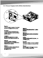
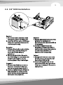
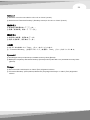
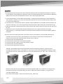
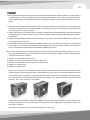
2.2 Power Supply Unit (PSU) Installation
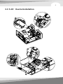
2.3 5.25” Device Installation
2
7
5
3
5
4
8
1
6
English /
Install the power supply unit in proper
location and secure it with screws.
Deutsche /
Installieren Sie das Netzteil an der
richtigen Position und sichern Sie es
mit Schrauben.
Français /
Mettez l'alimentation dans le bon
endroit et sécurisez-la avec des vis.
Español /
Instale la unidad de fuente de
alimentación en el lugar adecuado y
asegúrela con tornillos.
Italiano /
Installare l'unità dell'alimentatore in
modo appropriato e fissarla
utilizzando le viti.
繁體中文 /
將電源供應器安裝在適當位置,然後用
螺絲固定。
简体中文 /
将电源供应器单元安装至正确位置并以
螺丝固定。
日本語 /
電源装置を適切な場所に取り付け、ね
じで固定します。
Русский /
Установите блок питания в надлежа
щее место и закрепите его винтами.
Türkçe /
Güç kaynağı birimini uygun konuma
takın ve vidalarla sabitleyin.
3
4

Français /
1. Dévissez et retirez la tige.
2. Dévissez et détachez la cage à
disque dur 3.5” du châssis.
3. Poussez vers l'intérieur et vers le
haut pour déverrouiller le clip sans
outil sur la cage à disque dur 5.25”
4. Détachez le panneau avant du
châssis en poussant et relâchant
les 3 ressorts du panneau avant.
5. Insérez le périphérique 5.25” dans
la baie pour lecteur et poussez vers
l'intérieur et vers le bas pour
verrouiller le clip sans outil.
6. Sécurisez le périphérique 5.25”
avec des vis sur la côté opposé du
clip sans outil
7. Remettez la cage à disque dur 3.5"
dans son emplacement d'origine
dans le châssis et sécurisez-la avec
des vis.
8. Poussez pour remettre le panneau
avant dans son emplacement
d'origine.
Remarque: Pour un bon
fonctionnement de la baie de
lecteur 5.25”, il n'est pas
recommandé d'insérer le
périphérique 5.25" dans la seconde
ou troisième baie.
Español /
1. Desatornille y extraiga la vara.
2. Desatornille y separe el cajón del
HDD de 3,5 pulgadas del chasis.
3. Empuje hacia dentro y hacia arriba
para abrir el sujetador sin
herramientas del cajón del HDD de
5,25 pulgadas.
4. Separe el panel frontal del chasis
empujando y soltando los 3 muelles
del panel frontal.
5. Inserte el dispositivo de 5,25
pulgadas en la bahía de unidad y
empuje hacia dentro y hacia abajo
para cerrar el sujetador sin
herramientas.
6. Asegure, con tornillos, el
dispositivo de 5,25 pulgadas en el
lado opuesto del sujetador sin
herramientas.
7. Acople de nuevo el cajón del HDD
de 3,5 pulgadas en la posición
original del chasis y asegúrelo con
tornillos.
8. Presione para acoplar el panel
frontal de nuevo en la posición
original.
Advertencia: Si desea obtener un
funcionamiento correcto de la bahía
de unidad de 5,25 pulgadas, le
recomendamos que no inserte el
dispositivo de 5,25 pulgadas en la
2ª ó 3ª bahía.
English /
1. Unscrew and remove the rod.
2. Unscrew and detach the 3.5” HDD
cage from the chassis.
3. Push inward and upward to unlock
the tool-free clip on 5.25” HDD cage.
4. Detach the front panel from the
chassis by pushing and releasing
the 3 springs of the front panel.
5. Insert the 5.25” device into the
driver bay and push inward and
downward to lock the tool-free clip.
6. Secure the 5.25” device with screws
at the opposite side of the tool-free
clip
7. Attach the 3.5” HDD cage back to
the original location in the chassis
and secure it with screws.
8. Push to attach the front panel back
to the original location.
Notice: For correct operating 5.25"
drivebay, insert the 5.25" device
into the 2nd or 3rd bay is not
recommended.
Deutsche /
1. Lösen Sie die Schrauben und
entfernen Sie den Bügel.
2. Lösen Sie die Schrauben und
entfernen Sie den 3,5 Zoll HDD-
Käfig vom Gehäuse.
3. Drücken Sie einwärts und aufwärts,
um den Clip ohne Werkzeug auf
dem 5,25 Zoll HDD-Käfig zu
entsperren.
4. Entfernen Sie die Vorderseite vom
Gehäuse, indem Sie drücken und
die 3 Federn der Vorderseite
freigeben.
5. Führen Sie die 5,25 Zoll Einheit in
den Schacht ein und drücken Sie
einwärts und abwärts, um den
werkzeuglosen Clip zu befestigen.
6. Sichern Sie die 5,25 Zoll Einheit mit
Schrauben an den Seiten, die dem
werkzeuglosen Clip gegenüber
liegen.
7. Bringen Sie den 3,5 Zoll HDD-Käfig
wieder an seiner originalen Position
im Gehäuse an und sichern Sie ihn
mit Schrauben.
8. Drücken Sie, um die Vorderseite
wieder an ihren ursprünglichen
Platz zu bringen.
Hinweis: Für einen korrekt
arbeitenden 5,25 Zoll
Laufwerksschacht, wird es nicht
empfohlen, die 5,25 Zoll Einheit in
den 2. oder 3. Schacht einzubauen.
5
6
Page is loading ...
Page is loading ...
Page is loading ...
Page is loading ...
Page is loading ...
Page is loading ...
Page is loading ...
Page is loading ...

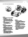
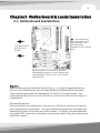
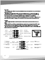
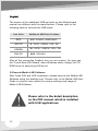
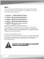
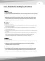
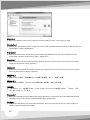
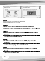
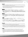
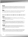
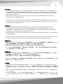
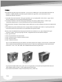
English /
Each motherboard has different standoff layout. It is highly suggested that you
refer to your motherboard's manual when installing motherboard into the case.
The cases are applicable with Standard ATX, Micro ATX motherboards. Your
motherboard may require a special I/O Panel, which should be included with your
motherboard.
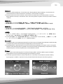
Placement Direction:
When installing the motherboard, make sure you follow the direction provided by
your motherboard manufacturer. On most standard motherboards, the edge with
external ports goes to the rear part of the chassis. It is highly recommended that
you install CPU, heat sink and modular components before fixing the motherboard
inside the chassis.
= the locations of
the screw holes. Note
these locations and
place included
standoffs on the chassis
first.
This side towards
the rear of the
chassis
Above illustration is a sample of what the
motherboard's layout. For more detail screw
hole placement, please refer to your mother
board manual.
Chapter3 Motherboard & Leads Installation
3.1 Motherboard Installation
简体中文 /
1. 顺时针转动 PCI 免用工具条以将其解除
锁定。
2. 向上拉 PCI 插槽的塑料扣具,然后卸下
PCI封片并将 PCI 卡插入 PCI 插槽。
3. 向下压塑料扣具,然后逆时针转动免用
工具条以将其锁定。
日本語 /
1. PCI工具不要バーを時計回りに回転し
てアンロックします。
2. PCIスロットのプラスチッククリップ
を上方に引っ張って、PCIブラケット
を取り外し、PCIスロットにPCIカード
を差し込みます。
3. プラスチッククリップを下側に押し
て、工具不要バーを反時計回りに回転
してロックします。
Русский /
1. Поверните планку PCI, не требующ
ую применения инструментов, по ча
совой стрелке, чтобы разблокирова
ть ее.
2. Вытяните пластмассовые фиксатор
ы разъемов PCI, извлеките кронште
йн PCI и установите плату PCI в раз
ъем PCI.
3. Нажмите на пластмассовые фиксат
оры и поверните планку, не требую
щую применения инструментов, про
тив часовой стрелки, чтобы заблоки
ровать ее.
Türkçe /
1. PCI araçsız çubuğunu saat yönünde
döndürerek çubuk kilidini açın.
2. PCI yuvalarının plastik kelepçelerini
yukarı doğru çekin ve daha sonra,
PCI plakasını çıkarıp PCI kartını PCI
yuvasının içine yerleştirin.
3. Plastik kelepçeleri aşağı itin ve
araçsız çubuğu saatin ters yönünde
döndürerek kilitleyin.
Español /
1. Gire la barra sin herramientas del
PCI en el sentido de las agujas del
reloj para cerrarla.
2. Tire hacia arriba de los
sujetadores de plástico de las
ranuras del PCI. A continuación,
extraiga el soporte del PCI e
inserte la tarjera del PCI en la
ranura para el PCI.
3. Presione los sujetadores de
plástico hacia abajo. A
continuación, gire la barra sin
herramientas en el sentido
contrario a las agujas del reloj
para cerrarla.
Italiano /
1. Ruotare la barra tool-free PCI in
senso orario per sbloccarla.
2. Tirare verso l'alto le clip in plastica
degli slot PCI, quindi rimuovere il
supporto PCI e inserire la scheda
PCI nello slot PCI.
3. Premere verso il basso le clip in
plastica, quindi ruotare la barra
tool-free in senso antiorario per
bloccarla.
繁體中文 /
1. 朝順時鐘方向轉動 PCI 免用工具橫
條以將它解除鎖定。
2. 向上拉 PCI 插槽的塑膠扣具,然後
拆下 PCI 封片並將 PCI 卡插入 PCI
插槽。
3. 向下按塑膠扣具,然後朝逆時鐘方
向轉動免用工具橫條以將它鎖定。
13
14
Page is loading ...
Page is loading ...
Page is loading ...

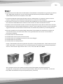
3.2 Case LED connections
English /
On the front of the case, you can find
some LEDs and switch leads (POWER
SW*1, POWER LED*1, H.D.D. LED*1,
RESET SW*1, SPEAKER*1).
Please consult user manual of your
motherboard manufacturer, then
connect these leads to the panel
header on the motherboard. These
leads are usually labeled; if not,
please trace them back to the case
front to find out their source.
- POWER LED
connects to your M/B at the PLED.
- POWER SW
connects to the PWR connector on
the motherboard.
- H.D.D LED
connects to the 2-pin labeled HDD
LED connector.
- RESET SW
connects to the RSW connector on
the motherboard.
- SPEAKER
connector: find out the 4-pin labeled
SPEAKER on the M/B then connect it.
Deutsche /
An der Frontseite des Gehäuses finden
Sie einige LEDs und Schalterkabel
(POWER SW*1, POWER LED*1, H.D.D.
LED*1, RESET SW*1,
LAUTSPRECHER*1).
Lesen Sie bitte das Handbuch zu Ihrer
Hauptplatine und verbinden Sie dann
diese Kabel mit den Steckplätzen auf
der Hauptplatine. Diese Kabel sind
normalerweise beschriftet; wenn das
nicht der Fall ist, verfolgen Sie sie bitte
zur Gehäusevorderseite zurück, um den
jeweiligen Anschluss herauszufinden.
- POWER LED
verbindet zu PLED (Power LED) auf der
Hauptplatine.
- POWER SW
verbindet zu PWR (Power) auf der
Hauptplatine.
- H.D.D LED
verbindet zu dem 2-poligen Anschluss
HDD LED.
- RESET SW
verbindet zu RSW (Reset) auf der
Hauptplatine.
- LAUTSPRECHER
Anschluss: Finden Sie den 4-poligen,
beschrifteten Anschluss für den
LAUTSPRECHER auf der Hauptplatine
und schließen Sie ihn an.
日本語 /
マザーボードの支柱レイアウトは、それぞれ異なっています。 マザーボードをケース
に取り付けるとき、マザーボードのマニュアルを参照するように、強くお勧めします。
ケースは標準のATX, Micro ATXマザーボードに適用可能です。 マザーボードには、標
準で装備される特別なI/Oパネルが必要です。
設置方向:
マザーボードを取り付けるとき、マザーボードメーカーの指示に従ってください。
もっとも標準なマザーボードでは、外部ポートのあるエッジはシャーシの背面部分を
向いています。 マザーボードをシャーシ内部に固定する前に、CPU、ヒートシンクお
よびモジュラーコンポーネントを取り付けるように強くお勧めします。
Русский /
Для каждой материнской платы применяется разная схема расположения прос
тавок. При установке материнской платы в корпус настоятельно рекомендуется
ознакомиться с руководством материнской платы. Корпусы совместимы с мате
ринскими платами стандартов Standard ATX, Micro ATX. Для материнской плат
ы может потребоваться специальная панель ввода/вывода, которая должна вх
одит в комплект материнской платы.
Направление установки
При установке материнской платы обязательно следуйте инструкции производ
ителя материнской платы относительно направления установки. На большинст
ве стандартных материнских плат край с внешними портами располагается в з
адней части корпуса. Перед креплением материнской платы внутри корпуса на
стоятельно рекомендуется установить ЦП, радиатор и модульные компоненты.
Türkçe /
Her ana kartın farklı bir yerleşim düzeni vardır. Ana kartı kasaya takarken ana
kartınızın kılavuzuna bakmanız şiddetle önerilir. Kasalar Standart ATX, Micro ATX
ana kartlarıyla kullanılabilir. Ana kartınızda, satın aldığınızda ana kartınızla birlikte
verilen özel bir G/Ç Panelini kullanmanız gerekebilir.
Yerleştirme Yönü:
Ana kartı takarken, ana kart üreticinizin talimatını uyduğunuzdan emin olun.
Standart ana kartların çoğunda, dış bağlantı noktalarının bulunduğu kenar kasanın
arka kısmına doğru yerleştirilir. CPU, ısı alıcı ve modüler bileşenleri, ana kartı
17
18
Page is loading ...
Page is loading ...
Page is loading ...
Page is loading ...

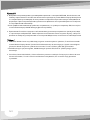
IEEE1394a
TPA+
VG
TPB+
VP
TPA-
(Brank)
TPB-
(Brank)
GND
English /
Deutsche /
IEEE 1394 Firewire-Anschluss
Bitte nehmen Sie die
Gebrauchsanweisung Ihres
Motherboards zur Hilfe und lesen Sie
unter dem Kapitel IEEE 1394 Firewire
Anschlüsse nach.
Français /
Connexion Firewire IEEE 1394
S'il vous plaît consultez le manuel de
votre carte mère à la section
"Connexion Firewire IEEE 1394".
Español /
Conexión de IEEE 1394 Firewire
Consulte el manual de la placa madre
para obtener más información sobre el
apartado”Conexión de IEEE1394
Firewire”.
IEEE1394 Firewire connection
Please consult your motherboard
manual to find out the section of
"IEEE1394 Firewire connection".
Italiano /
Connessione Firewire IEEE 1394
Fare riferimento al manuale sulla
scheda madre per consultare la
sezione”Connessione Firewire IEEE
1394”.
繁體中文 /
連接 IEEE 1394 Firewire
請參閱主機板使用手冊的「連接 IEEE
1394 Firewire」部分。
简体中文 /
连接 IEEE 1394 Firewire
请参阅主板使用手册的“连接 IEEE 1394
Firewire”部分。
日本語 /
IEEE 1394 Firewireの接続
マザーボードのマニュアルを参照して、
「IEEE 1394 Firewire接続」のセク
ションを確認してください。
Русский /
Подключение IEEE 1394 Firewire
См. раздел «Подключение IEEE
1394 Firewire» в руководстве матер
инской платы.
Türkçe /
IEEE 1394 Firewire bağlantısı
Lütfen ana kart kılavuzunuzun “IEEE
1394 Firewire connection” (IEEE
1394 Firewire bağlantısı) bölümüne
bakın.
3.3 USB2.0 & IEEE1394 Firewire connection
USB2.0
GND1
Data+1
Data-1
GND2
Data+2
Data-2
Vcc 2
(Brank)
Vcc1
English /
Deutsche /
USB-Anschluss
Bitte nehmen Sie die
Gebrauchsanweisung Ihres
Motherboards zur Hilfe und lesen Sie
unter dem Kapitel USB Anschlüsse
nach.
Français /
Connexion USB
S'il vous plaît consultez le manuel de
votre carte mère à la section
"Connexion USB".
Español /
Conexión USB
Consulte el manual de la placa madre
para obtener más información sobre el
apartado “Conexión USB".
USB connectionUSB connection
Please consult your motherboard
manual to find out the section of "USB
connection".
Italiano /
Connessione USB
Fare riferimento al manuale sulla
scheda madre per consultare la
sezione “Connessione USB”.
繁體中文 /
連接 USB
若要找出「連接 USB」部分,請參閱主
機板使用手冊。
简体中文 /
连接 USB
请参阅主板使用手册的“连接 USB”部分。
日本語 /
USB接続
マザーボードのマニュアルを参照して、
「USB接続」のセクションを確認してくださ
い。
Русский /
Подключение USB
См. раздел «Подключение USB» в руково
дстве материнской платы.
Türkçe /
USB bağlantısı
Lütfen ana kart kılavuzunuzun “USB
connection” (USB bağlantısı)
bölümüne bakın.
23
24

Italiano /
- Fare riferimento all'illustrazione riportata di seguito del connettore Audio e al
manuale utente per la scheda madre.
- Selezionare la scheda madre utilizzata per AC'97 o HD Audio (Azalia). Verificare
che l'audio supporti AC'97 o HD Audio (Azalia); in caso contrario i dispositivi
potrebbero venire danneggiati.
- In alcune schede madri, i connettori per Audio non sono uguali a quelli riportati
nell'illustrazione seguente. Consultare il manuale utente sulla scheda madre prima
dell'installazione.
繁體中文 /
- 請參閱下列音訊接頭的圖解和主機板使用手冊。
- 請選擇使用 AC'97 或 HD Audio (Azalia) 的主機板 (請注意您的音訊是否支援 AC' 97
或 HD Audio (Azalia)),否則會損壞您的主機板。
- 在有些主機板上,音訊使用的接頭和下圖所示的不相同。 安裝前,請先參閱主機板使
用手冊。
简体中文 /
- 请参阅以下音频连接器图解以及主板使用手册。
- 请选择使用 AC'97 或 HD Audio (Azalia) 的主板(请注意音频是否支持 AC'97 或 HD
Audio (Azalia)),否则会损坏您的主板。
- 在有些主板上,音频使用的连接器和以下图示有所不同。 安装前,请先参阅主板的使
用手册。
日本語 /
- オーディオコネクタの次の図とマザーボードのユーザーマニュアルを参照してくだ
さい。
- AC'97またはHDオーディオ(Azalia)を使用するマザーボードを選択してください(オ
ーディオがAC'97またはHDオーディオ(Azalia)をサポートしていることを確認してく
ださい。サポートしていないと、デバイスが損傷します)。
- 一部のマザーボードの場合、オーディオのコネクタが以下の図と異なっていること
があります。 取り付ける前に、マザーボードのマニュアルで確認してください。
3.4 Audio connection
English /
Deutsche /
- Bitte beachten Sie die folgende Abbildung der Audio-Anschlüsse und die Anweisung
in der Gebrauchsanweisung Ihres Motherboards.
- Bitte wählen Sie das Motherboard, das AC'97 oder HD Audio(Azalia) verwendet,
(achten Sie darauf, dass Ihr Audio AC'97 bzw. HD Audio (Azalia unterstützt)).
Andernfalls entstehen schwere Schäden an Ihrem(n) Gerät(en).
- Auf einige Hauptplatinen entsprechen die Anschlüsse für Audio nicht denen auf der
Abbildung hier. Bitte konsultieren Sie das Benutzerhandbuch Ihrer Hauptplatine,
bevor Sie installieren.
Français /
- S'il vous plaît référez vous à l'illustration suivante du connecteur audio et au guide
de l'utilisateur de votre carte mère.
- S'il vous plaît sélectionnez la carte mère qui utilise l'audio AC'97 ou HD (Azalia),
(soyez attentif à ce que votre audio supporte l'AC'97 ou l'audio HD (Azalia) ou bien
cela peut endommager votre(s)appareil(s).
- Sur certaines cartes mères, les connecteurs audio ne sont pas les mêmes que ceux
dessinés ci-dessus. S'il vous plaît vérifiez avec le manuel de votre carte mère avant
l'installation.
Español /
- Consulte la siguiente ilustración del conector de Audio y el manual del usuario de la
placa madre.
- Seleccione la placa madre que utiliza AC'97 o HD Audio (Azalia), (asegúrese de que
su audio admite AC'97 o HD Audio (Azalia)) si no, sus dispositivos resultarán
dañados.
- En algunas placas madre, los conectores para Audio no son iguales a los del dibujo
siguiente. Compruébelo en el manual de la placa madre antes de iniciar la instalación.
- Please refer to the following illustration of Audio connector and your motherboard
user manual.
- Please select the motherboard which used AC'97 or HD Audio (Azalia), (be aware of
that your audio supports AC'97 or HD Audio (Azalia)) or it will damage your device(s).
- On some motherboards, the connectors for Audio are not the same as the drawing
below. Please check with your motherboard manual before installing.
25
26
Page is loading ...

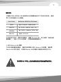
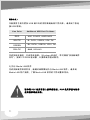
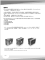
3.5 Case open alarm function ( Intrusion switch )
Black Wire
Whit e Wire
1
2
English /
Deutsche /
1.Kabel mit 2-poliger Verbindung (Micro SW) auf der Rückseite innerhalb des
Gehäuses finden.
2.Position des Gehäusealarms auf Ihrem Motherboard finden (Bitte lesen Sie
in Ihrem Motherboard Handbuch nach).
Français /
1.Pour trouver le câble avec connecteur à 2n broches (Micro SW) à l'arrière de
l'intérieur du châssis.
2.Pour trouver la position d'alarme du châssis sur votre carte mère. (Veuillez
consulter le manuel de votre carte mère)
Español /
1.Para obtener información sobre el cable con conector de dos pines (Micro
SW) de la parte posterior del interior del chasis.
2.Para obtener información sobre la ubicación de la Alarma del chasis de la
placa madre. (le rogamos consulte el manual de la placa madre)
1.To find out the cable with 2pin connector (Micro SW) from the rear of inside
the chassis.
2.To find out the position of Chassis Alarm on your motherboard.(please
consult your motherboard manual)
Русский /
- См. следующую иллюстрацию аудиоразъема и руководство пользователя мат
еринской платы.
- Выберите материнскую плату, в которой используется кодек AC’97 или HD
Audio (Azalia) (убедитесь, что звуковая плата поддерживает кодек AC’97 или
HD Audio (Azalia)). В противном случае можно повредить устройства.
- На некоторых материнских платах аудиоразъемы отличаются от представлен
ных на рисунке ниже. Перед установкой см. руководство материнской платы.
Türkçe /
- Lütfen aşağıdaki Ses konektörü resmine ve ana kartınızın kullanım kılavuzuna
bakın.
- Lütfen AC'97 veya HD Ses (Azalia) kullanan ana kart seçin (sesinizin AC'97 veya
HD Sesi (Azalia) desteklediğinden emin olun); yoksa, aygıt(lar)ınız zarar görür.
- Bazı ana kartlarda, Ses konektörleri aşağıdaki çizimle aynı olmaz. Lütfen takmadan
önce ana kartınızı kontrol edin.
PRESENCE#BLACK
SENSE1_RETURN
AUD GND
SENSE2_RETURN
YELLOW
BROWN
RED
PORT1 R
PORT2 R
PORT1 L
BLUE
PORT2 L
SENSE_SEND
KEY
PURPLE
GREEN
AUDIO AZALIA Function
ORANGE
BLACK
GROUND
Front
Audio Ground
L-RET
Rear Left Channel
Audio Signal
Rear Right Channel
Audio Signal
R-RET
NCBROWN
REDMIC IN
MIC POWER
Front Microphone
Power
Front Microphone
input Signal
KEY
BLUE
NC
BLUE
L-OUT
Front Left Channel
Audio Signal
Front Right Channel
Audio Signal
YELLOWR-OUT
AUDIO AC'97 Function
BLACK
YELLOW
27
28
Page is loading ...
Page is loading ...

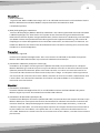
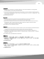
Chapter4 Front Buttons Instruction
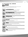
4.1 Media LAB Hot keys Module
function instruction:(Optional)
English /
DH Series supports the latest VFD kit. The VFD not only supports the latest
multimedia functions, it also supports a set of Hot Keys function. The simple design
will allow users to control the system simply through a touch on thefront panel.
Sound Volume Control Button
This is used for volume up and down / pressing for mute.
iMEDIAN Button (MCE)
This allows to go to the application program directly.
It can be user-defined.
App. Exit Button
This quits the application program.
It works same as "ALT+F4”.
Esc Button
This is used to go backward on iMEDIAN or MCE.
Direction Button
This is arrow key to move up/down/left/right.
Star Button
This is the same as the windows icon key on the keyboard.
Menu Button
This is same as the menu button of the Media LAB remote control.
Enter Button
This is used to enter the function that you choose.
Italiano /
1.Individuare il cavo con il connettore a 2 pin (Micro SW) nella parte posteriore
interna dello chassis.
2.Individuare la posizione dell'Allarme chassis nella scheda madre. (consultare il
manuale sulla scheda madre)
繁體中文 /
1.在機殼內部的後面找出帶 2-pin 接頭 (Micro SW) 的纜線。
2.在主機板上找出機殼警報器的位置。 (請參閱主機板使用手冊)
简体中文 /
1.从机箱内后部找出带 2 针连接器的缆线 (Micro SW)。
2.找出机箱警告装置在主板上的位置。 (请参阅主板使用手册)
日本語 /
1.シャーシ内部の背面から2ピンコネクタ(Micro SW(ミクロSW))の付いたケーブルを確認します。
2.マザーボードでシャーシアラームの位置を確認します。 (マザーボードマニュアルを参照してくだ
さい)
Русский /
1.Для поиска кабеля с 2-контактным разъемом (Micro SW), идущего от задней ч
асти внутри корпуса.
2.Для поиска расположения разъема Chassis Alarm на материнской плате. (см.
руководство материнской платы)
Türkçe /
1.Kasanın iç arka tarafından 2 pimli konektörü olan kabloyu (Micro SW) bulmak için.
2.Ana kartınızdaki Kasa Alarmı'nın yerini bulmak için. (lütfen ana kartınızın
kılavuzuna bakın)
29
30
Page is loading ...
Page is loading ...
Page is loading ...
Page is loading ...
Page is loading ...
Page is loading ...
Page is loading ...
Page is loading ...
Page is loading ...

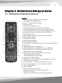
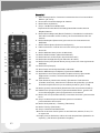
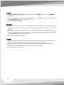
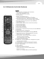
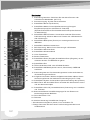
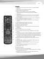
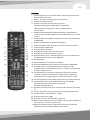
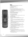
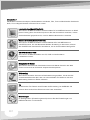
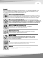
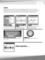
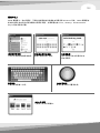
English /
1. Application Exit : Closing the active window or
Closing Multi Median [ALT+F4]
2. Power : Turn On/OFF the system
3. Record Button
4. Media Control Button group 1
Play/Pause/Open/Prev./Next/Rew./F.Fwd/Stop
5. Mouse/Keyboard button : Switching the usage of PAD
controller between mouse and keyboard 4 way arrow keys
6. Backspace Button to the previous view of iMEDIAN
7. Select/Space button
8. PAD controller : Mouse cursor control & 4 arrow Keys
9. Windows Start Button
10. Windows Menu Button
11. Mouse Left Click Button
12. Mouse Right Click Button
13. Enter Button : Enter Button to go to the next view of iMEDIAN
14. ESC Button
15. Open/Close DVD or CD ROM tray
16. iMEDIAN (Quick Launch) Button : Running iMEDIAN
17. Application Launcher : Running Application Launcher,
Easiest way to run the application
18. Task Switcher : Running Task Switcher, select the
application window among the
running applications. [ALT +TAB]
19. System Volume Mute Button
20. iMON Timer : Running iMON Timer, management of power
on/off and alarm schedule
21. VOL/CH Button : Control of Volume and TV channel
22. Custom button group for user customized command.
23. Shift + Tab key Button
24. Tab key Button
25. Media Control Buttons Group 2
* Short-cut buttons to move to my Movie, Music,
Photo,TV in running
* Movie Tip : Use Aspect Ratio and Full Screen Button
1
2
3
4
5
6
7
8
9
10
11
12
13
14
15
16
17
18
19
20
21
22
23
24
25
Chapter 5 DH202 Media Kits Quick Guide
5.1 IR Remote Controller Features
Türkçe /
DH Serisi en son VFD takımını destekler. VFD yalnızca en son multimedya
işlevlerini değil, aynı zamanda bir dizi Kısayol Tuşu işlevini de destekler.
Basit tasarım, kullanıcıların ön panelde bir dokunuşla sistemi kolayca
kontrol edebilmelerini sağlar.
iMEDIAN Düğmesi (MCE)
Bu düğme, doğrudan uygulama programına yönlendirir.
Kullanıcı tarafından tanımlanabilir.
App. Exit (Uyg. Çıkış) Düğmesi
Bu düğme, uygulama programından çıkar. “ALT+F4” ile aynı
şekilde çalışır.
Esc (Çıkış) düğmesi
Bu, iMEDIAN veya MCE'ye geri dönmenizi sağlar.
Direction (Yön) düğmesi
Bu, yukarı/aşağı/sola/sağa hareket etmek
için kullanılan ok tuşudur.
Start (Başlat) Düğmesi
Bu düğme, klavyedeki Windows simgesinin
bulunduğu tuşla aynıdır.
Menu (Menü) düğmesi
Bu, Media LAB uzaktan kumandasındaki Menu (Menü)
düğmesiyle aynıdır.
Sound Volume Control (Ses Seviyesi Denetimi) Düğmesi
Bu, ses seviyesini yükseltmek ve düşürmek için kullanılır
/ basıldığında, sesi kapatır.
Giriş Düğmesi
Bu düğme, seçtiğiniz işleve girmek için kullanılır.
39
40
Page is loading ...
Page is loading ...
Page is loading ...
Page is loading ...
Page is loading ...
Page is loading ...
Page is loading ...
Page is loading ...
Page is loading ...

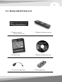
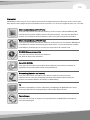
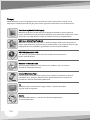
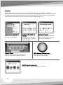
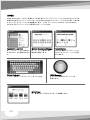
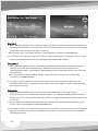
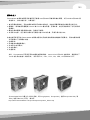
5.2 Media LAB Kit Item List
1 Media LAB LCD
(Internal IR Receiver)
1 Media LAB Remote Control
1 Quick Guide
1 Media LAB Application CD
1 Extension USB Cable
2 AAA Batteries
1
2
3
4
5
6
7
8
9
10
11
12
13
14
15
16
17
18
19
20
21
22
23
24
25
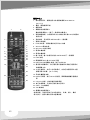
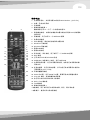
Türkçe /
1. Uygulama Çıkışı: Etkin pencereyi veya Multi Median
uygulamasını kapatır. [ALT+F4]
2. Güç: Sistemi açar/kapatır
3. Kayıt Düğmesi
4. Ortam Denetimi Düğmesi grup 1
Çal/Duraklat/Aç/Önceki/Sonraki/Geri Sar/İleri Sar/ Durdur
5. Fare/Klavye düğmesi: Altlık denetleyicinin kullanımını fare ve
klavyenin 4 yönlü ok tuşları arasında değiştirir
6. Geri Düğmesi iMEDIAN programının önceki görünümüne döner
7. Seç/Ara düğmesi
8. Altlık denetleyici: Fare imleci denetimi ve 4 ok Tuşu
9. Windows Start (Başlat) Düğmesi
10. Windows Menu (Menü) Düğmesi
11. Fare Sol Tıklatma Düğmesi
12. Fare Sağ Tıklatma Düğmesi
13. Giriş Düğmesi: Giriş Düğmesi, iMEDIAN programının sonraki
görünümüne gider
14. ESC (Çıkış) düğmesi
15. DVD veya CD ROM tepsisini aç/kapat
16. iMEDIAN (Hızlı Başlatma) Düğmesi: iMEDIAN programını
çalıştırır
17. Application Launcher (Uygulama Başlatıcı): Uygulama
çalıştırmanın en kolay yolu olan Application Launcher işlevini
çalıştırır
18. Task Switcher (Görev Değiştirici): Task Switcher, çalışan
uygulamalar arasından uygulama penceresini seçmek için
kullanılır [ALT +SEKME]
19. Sistem Ses Düzeyi Sessiz Düğmesi
20. iMON Timer (iMON Zamanlayıcısı): iMON Timer (iMON
Zamanlayıcısı) uygulaması, birimi açma/kapatma ve uyarı
zamanlamasının yönetimi için kullanılır
21. VOL/CH (SES/KNL) Düğmesi: Ses Düzeyi ve TV kanalı
işlevlerini kontrol eder
22. Kullanıcının özelleştirdiği komutlar için özel düğme grubu.
23. Üst Karakter + Sekme tuşu Düğmesi
24. Sekme tuşu Düğmesi
25. Ortam Denetimi Düğmeleri Grup 2
* Ürün çalışırken my Movie (Sinemam), Music (Müziğim), Photo
(Fotoğrafım), TV (Televizyonum) bölümlerine geçmeye ilişkin
kısayol düğmeleri
* Sinema İpucu: Aspect Ratio (En Boy Oranı) ve Full Screen (Tam
Ekran) Düğmesini kullanın
49
50

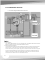
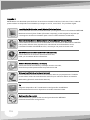
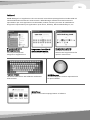
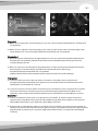
5.3 Installation Process
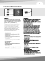
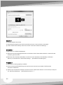
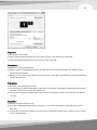
English /
1) S/W Installation
Insert 'Media LAB Application CD' to your CD ROM, and install Media LAB software and Multi-
Median according to the auto running S/W installation process.
2) H/W (IR Receiver) Installation
Internal IR Receiver (Media LAB VFD) Installation The feature of internal type Media LAB IR
receiver is that you can power on your PC system using the power button of the remote
control. After turn off your PC system, open your PC cover and connect the cable to its proper
pin refer to the following picture. Internal IR receiver is connected to motherboard with two
cables, PC case with one cable, Power Supply with another cable. You should be careful to
connect these four cables refer to your motherboard manual.
Connection Diagram Media LAB Inside/VFD
Deutsche /
Français /
Español /
1) S/W-Installation
Legen Sie die 'Media LAB Anwendungs-CD' in Ihr CD ROM-Laufwerk ein und installieren Sie die
Media LAB Software und Multi-Median entsprechend dem automatischen S/W-
Installationsprozess.
2) H/W (IR-Empfänger) Installation
Interner IR-Empfänger (Media LAB VFD) Installation. Das Leistungsmerkmal des internen Media
LAB IR-Empfängers ist, dass Sie Ihr PC-System mit der Fernsteuerung einschalten können.
Nachdem Sie das PC-System ausgeschaltet haben, öffnen Sie Ihre PC-Abdeckung und verbinden
das Kabel mit dem entsprechenden Anschluss gemäß der folgenden Abbildung. Der interne IR-
Empfänger ist mit der Hauptplatine über zwei Kabel verbunden, ein Kabel zum PC-Gehäuse, ein
Kabel zum Netzteil. Sie sollten beim Anschließen dieser vier Kabel vorsichtig sein, lesen Sie das
Handbuch zu Ihrer Hauptplatine.
1) Installation logicielle
Insérez le CD 'Media LAB Application' dans votre lecteur de CD ROM, et installez les logiciels
Media LAB et Mulit-Media selon le processus d'installation automatique.
2) Installation matérielle (récepteur Infrarouge)
Installation du récepteur Infrarouge Interne (Media LAB VFD) La caractéristique du récepteur
Media LAB IR de type interne est que vous pouvez allumer votre PC en utilisant le bouton Power
(Marche) de la télécommande. Après avoir éteint votre PC, ouvrez le couvercle de votre PC et
connectez le câble à sa bonne fiche comme indiqué sur l'image. Le récepteur Infrarouge interne
est connecté à la carte mère avec deux câbles, le boîtier du PC avec un câble, l'alimentation avec
l'autre câble. Vous devrez faire attention à connecter ces quatre câbles en vous référant au
manuel de votre carte mère.
1) Instalación del Software.
Inserte el “Media LAB Application CD” en el CD ROM e instale el software Media LAB y Multi-
Median según el proceso de instalación automática del software.
2) Instalación del Hardware (Receptor IR)
Instalación del Receptor IR Interno (Media LAB VDF) La característica del receptor IR interno tipo
Media LAB es que usted puede encender el sistema del PC utilizando el botón de encendido del
mando a distancia. Después de apagar el sistema del PC, abra la tapa del mismo y conecte el
cable en el pin adecuado, consulte el siguiente esquema. El receptor IR interno está conectado a
la placa madre con dos cables, a la caja del PC con un cable y a la Fuente de Alimentación con
otro cable. Debe tener cuidado a la hora de conectar estos cuatro cables, consulte el manual de la
placa madre.
51
52
Page is loading ...
Page is loading ...
Page is loading ...

1. Anschlusskabel Stand-by Stromversorgung
2. Anschlusskabel Hauptplatine-Stromversorgungsschalter
3. PC-Gehäuse Stromversorgungsschalter-Anschlusskabel
4. Hauptplatine USB-Anschlusskabel
A1: (2-polig, Media LAB innn 'ST
PWR1' Anschluss)
A2: (2-polig, Erweiterung
Stromkabel Hauptplatine)
B1: (2-polig Media LAB innen 'M/B
PWR' Anschluss)
B2: (2-polig, Hauptplatine-
Stromschalter-Anschluss)
C1: (2-polig, Media LAB innen
'PWR S/W' Anschluss)
C2: (2-polig, PC-Gehäuse
Stromschalteranschluss)
D1: (5-polig, Media LAB innen
USB-Anschluss)
D2 : (4-polig, Hauptplatine USB
interner Anschluss)
Deutsche /
1. Stand-By Power Connection Cable
A1 : (2pin, Media LAB Inside
'ST PWR1' connector)
A2 : (2pin, Motherboard power
extension cable)
2. Motherboard Power Switch Connection Cable
B1 : (2pin, Media LAB Inside
'M/B PWR' connector)
B2 : (2pin, Motherboard power
switch connector)
4. Motherboard USB Connection Cable
D1 : (5pin, Media LAB Inside
USB connector)
D2 : (4pin, Motherboard USB
internal connector)
3. PC Case Power Switch Connection Cable
C1 : (2pin, Media LAB Inside
'PWR S/W' connector)
C2 : (2pin, PC Case power
button connector)
English /
55
56
Page is loading ...
Page is loading ...
Page is loading ...
Page is loading ...
Page is loading ...
Page is loading ...
Page is loading ...
Page is loading ...
Page is loading ...

Line Color
Additional USB Port Pin Name
RED
WHITE
GREEN
BALCK
VCC, POWER, USBPOWER
D-, DATA-, USBP#-, UP#-, P#-
D+, DATA+, USBP#+, UP#+, P#+
GND, GROUND
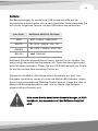
!
Die Bezeichnungen für zusätzliche USB-Anschlussstifte auf der
Hauptplatine unterscheiden sich je nach Hersteller. Bitte orientieren Sie
sich an der folgenden Tabelle, um das USB-Kabel anzuschließen.
Nachdem Sie alles angeschlossen haben, starten Sie Ihr System. Sie
sehen möglicherweise den Assistenten für "Neue hardware gefunden",
wenn Windows hochfährt. Geben Sie das CD ROM Laufwerk als Quelle
für die Suche nach dem Hardware-Treiber an.
Starten Sie die Media LAB SoftwareNach Abschluss der Soft- und
Hardware-Installation starten Sie bitte die Media LAB Software, indem
Sie auf das entsprechende Desktop-Symbol klicken. Lesen Sie bitte im
Media LAB Benutzerhandbuch nach, wie die Media LAB Software
eingerichtet und benutzt wird.
Bitte lesen Sie die detaillierten Beschreibungen im PDF-
Handbuch, das zusammen mit der Software installiert
wird.
Deutsche /
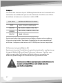
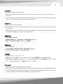
The names of the additional USB port pins on the Motherboard
manual are different with the manufacturer. Please refer to the
following table to connect the USB cable.
Line Color
Additional USB Port Pin Name
RED
WHITE
GREEN
BALCK
VCC, POWER, USBPOWER
D-, DATA-, USBP#-, UP#-, P#-
D+, DATA+, USBP#+, UP#+, P#+
GND, GROUND
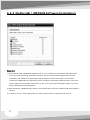
After all the connection finished, turn on your system. You may see
the 'Found New H/W Wizard' when Windows starts. Assign the CD
ROM drive for searching H/W driver.
3) Execute Media LAB Software
After finish S/W and H/W installation, please execute the Media LAB
Software using the desktop icon. Please refer to the Media LAB User
Guide in order to learn about the various settings and usage of
Media LAB Software.
!
Please refer to the detail description
on the PDF manual which is installed
with S/W applications.
English /
65
66
Page is loading ...
Page is loading ...
Page is loading ...
Page is loading ...
Page is loading ...
Page is loading ...
Page is loading ...
Page is loading ...
Page is loading ...

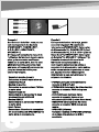
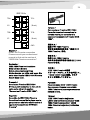
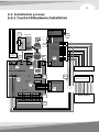
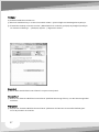
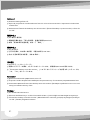
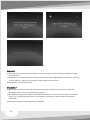
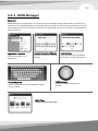
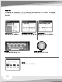
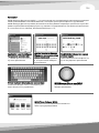
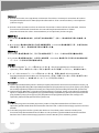
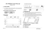
6.2 Installation process
6.2.1 Touch LCD Hardware Installation
Ma inboard
Graphic
Card
Touc h LCD MAIN PCB
KNOB BOARD
BUTTON BOA RD
IR
BOARD
Powe r Button
M/ B
PWR SW
Co nnec tor
VGA
CN4
PWR SW
JP2
IR BOAR D
CN10
M/ B PWR
SW JP3
24 /4 PWR EXT
CN15
KNO B BOAR D
CN13
US B
CN12
BU TTON BOARD
CN9
Power Su pp ly
M/ B Mai n
Powe r Conn ec tor
(2 0 or 24 pi n typ e)
US B Por t Int ernal
Co nnec tor
ST_PWR
GND
5V_CHK
12V
C1
G1
F1
H1
H2
F2
D2
G2
D1
A2
A1
VC C
D-
D+
GND
PC Case
VCC
D-
D+
GND
S/GND
E1
B1
C2
E2
B2
VG A
Co nn ector
Power Sup pl y Con ne ctor
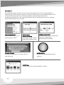
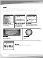
Chapter 6 DH202 Touch LCD Installation Guide
6.1 Touch LCD Kit Item List
Remote Control
Main Board with Chassis
IR Borad
Knob Board
Button Board
VGA Cable
24-4 pin PWR EXT Cable
IR EXT Cable
Knob EXT Cable Button EXT Cable
USB Cable Internal USB EXT Cable
M/B PWR SW Cable PCI Bracket Installation CD
Battery
75
76
Page is loading ...
Page is loading ...
Page is loading ...
Page is loading ...
Page is loading ...
Page is loading ...
Page is loading ...
Page is loading ...
Page is loading ...
Page is loading ...
Page is loading ...
Page is loading ...
Page is loading ...
Page is loading ...
Page is loading ...
Page is loading ...
Page is loading ...
Page is loading ...
Page is loading ...
Page is loading ...
Page is loading ...
Page is loading ...
Page is loading ...
Page is loading ...
Page is loading ...
Page is loading ...
Page is loading ...
Page is loading ...
Page is loading ...
Page is loading ...
Page is loading ...
Page is loading ...
Page is loading ...
Page is loading ...
Page is loading ...
Page is loading ...
Page is loading ...
Page is loading ...
Page is loading ...
Page is loading ...
Page is loading ...
Page is loading ...
Page is loading ...
Page is loading ...
Page is loading ...
Page is loading ...
Page is loading ...
Page is loading ...
Page is loading ...
Page is loading ...
Page is loading ...
Page is loading ...
Page is loading ...
Page is loading ...
Page is loading ...
Page is loading ...
Page is loading ...
Page is loading ...
Page is loading ...
Page is loading ...
Page is loading ...
Page is loading ...
Page is loading ...
Page is loading ...
Page is loading ...
Page is loading ...
Page is loading ...
Page is loading ...
Page is loading ...
Page is loading ...
Page is loading ...
Page is loading ...
Page is loading ...
Page is loading ...
Page is loading ...
Page is loading ...
Page is loading ...
Page is loading ...
Page is loading ...
Page is loading ...
Page is loading ...
Page is loading ...
Page is loading ...
Page is loading ...
Page is loading ...
Page is loading ...
Page is loading ...
Page is loading ...
Page is loading ...
-
 1
1
-
 2
2
-
 3
3
-
 4
4
-
 5
5
-
 6
6
-
 7
7
-
 8
8
-
 9
9
-
 10
10
-
 11
11
-
 12
12
-
 13
13
-
 14
14
-
 15
15
-
 16
16
-
 17
17
-
 18
18
-
 19
19
-
 20
20
-
 21
21
-
 22
22
-
 23
23
-
 24
24
-
 25
25
-
 26
26
-
 27
27
-
 28
28
-
 29
29
-
 30
30
-
 31
31
-
 32
32
-
 33
33
-
 34
34
-
 35
35
-
 36
36
-
 37
37
-
 38
38
-
 39
39
-
 40
40
-
 41
41
-
 42
42
-
 43
43
-
 44
44
-
 45
45
-
 46
46
-
 47
47
-
 48
48
-
 49
49
-
 50
50
-
 51
51
-
 52
52
-
 53
53
-
 54
54
-
 55
55
-
 56
56
-
 57
57
-
 58
58
-
 59
59
-
 60
60
-
 61
61
-
 62
62
-
 63
63
-
 64
64
-
 65
65
-
 66
66
-
 67
67
-
 68
68
-
 69
69
-
 70
70
-
 71
71
-
 72
72
-
 73
73
-
 74
74
-
 75
75
-
 76
76
-
 77
77
-
 78
78
-
 79
79
-
 80
80
-
 81
81
-
 82
82
-
 83
83
-
 84
84
-
 85
85
-
 86
86
-
 87
87
-
 88
88
-
 89
89
-
 90
90
-
 91
91
-
 92
92
-
 93
93
-
 94
94
-
 95
95
-
 96
96
-
 97
97
-
 98
98
-
 99
99
-
 100
100
-
 101
101
-
 102
102
-
 103
103
-
 104
104
-
 105
105
-
 106
106
-
 107
107
-
 108
108
-
 109
109
-
 110
110
-
 111
111
-
 112
112
-
 113
113
-
 114
114
-
 115
115
-
 116
116
-
 117
117
-
 118
118
-
 119
119
-
 120
120
-
 121
121
-
 122
122
-
 123
123
-
 124
124
-
 125
125
-
 126
126
-
 127
127
-
 128
128
-
 129
129
-
 130
130
-
 131
131
-
 132
132
-
 133
133
-
 134
134
-
 135
135
-
 136
136
-
 137
137
-
 138
138
-
 139
139
-
 140
140
-
 141
141
-
 142
142
-
 143
143
-
 144
144
-
 145
145
-
 146
146
-
 147
147
-
 148
148
-
 149
149
-
 150
150
-
 151
151
-
 152
152
-
 153
153
-
 154
154
-
 155
155
-
 156
156
-
 157
157
-
 158
158
-
 159
159
-
 160
160
-
 161
161
-
 162
162
-
 163
163
-
 164
164
-
 165
165
-
 166
166
-
 167
167
-
 168
168


Thermaltake 01THV85540001 User manual
- Category
- Computer cases
- Type
- User manual
- This manual is also suitable for
Ask a question and I''ll find the answer in the document
Finding information in a document is now easier with AI
in other languages
- italiano: Thermaltake 01THV85540001 Manuale utente
- français: Thermaltake 01THV85540001 Manuel utilisateur
- español: Thermaltake 01THV85540001 Manual de usuario
- Deutsch: Thermaltake 01THV85540001 Benutzerhandbuch
- русский: Thermaltake 01THV85540001 Руководство пользователя
- Türkçe: Thermaltake 01THV85540001 Kullanım kılavuzu
- 日本語: Thermaltake 01THV85540001 ユーザーマニュアル
Related papers
-
Thermaltake CA-1B4-00M1WN-00 User manual
-
Thermaltake Level 10 GTS User manual
-
-
Thermaltake A2331 User manual
-
-
-
-
-
-
Thermaltake Urban S71 User manual
Other documents
-
Acer Aspire X1700 User manual
-
NOX NOXLIVE2 Datasheet
-
 Acrosser Technology AR-M9936 Quick Manual
-
DeLOCK 89106 Datasheet
-
Corsair 730T Installation guide
-
Corsair Graphite 760T Installation guide
-
Antec Multimedia Station E-Z Installation guide
-
Antec Multimedia Station Elite Installation guide
-
Akasa GenesisM User manual
-
Philips SWF2620/10 User manual
