Page is loading ...

M968382A
U.S. Patent No. D403,750
Patente estadounidense D403,750
Brevet USA no. D403.750
4"
1/2" NPT
1/2" (12,7 MM) NPT
NPT 12,7 mm (1/2 po.)
1/2" NPT
1/2" (12,7 MM) NPT
NPT 12,7 mm (1/2 po.)
1
ROUGHING-IN
Turn off water at main supply.
CAUTION
When soldering, remove PLASTER GUARD, CARTRIDGES and CHECK STOPS (IF PRESENT). When finished soldering,
flush valve body, replace cartridges, check stops (if present) and plaster guard to continue installation. Use thread
sealant or Teflon tape on threaded connections.
NOTE
4-1/16"
(103 MM)
4-1/16"
(103 MM)
4-1/16"
(103 MM)
OUTLETS 1/2" NOM.
COPPER SWEAT
SALIDA
, 1/2" (12,7 MM)
NOM. COBRE SOLDADO
ORIFICE
CUIVRE LISSE
12,7 mm (1/2 po.) NOM.
OUTLETS 1/2" NOM.
COPPER SWEAT
SALIDA
, 1/2" (12,7 MM)
NOM. COBRE SOLDADO
ORIFICE
CUIVRE LISSE
12,7 mm (1/2 po.) NOM.
INLETS 1/2" NOM.
COPPER SWEAT
ENTRADAS, 1/2" (12,7 MM)
NOM. COBRE SOLDADO
ENTRÉES CUIVRE LISSE
12,7 mm (1/2 po.) NOM.
INLETS 1/2" NOM.
COPPER SWEAT
ENTRADAS, 1/2" (12,7 MM)
NOM. COBRE SOLDADO
ENTRÉES CUIVRE LISSE
12,7 mm (1/2 po.) NOM.
SWEAT INLETS
ENTRADAS SOLDADAS
ENTRÉES LISSES
THREADED INLETS (STOPS)
ENTRADAS ROSCADAS (LIMITADORES)
ENTRÉES FILETÉES (BUTÉES)
INLETS
1/2" NPT
ENTRADAS, 1/2"
(12,7 MM) NPT
ENTRÉES NPT
12,7 mm (1/2 po.)
If the valve is installed on a fiberglass
or other thin wall application, the
PLASTER GUARD (4) can be used as a support.
Connect hot and cold water supplies.
Cap off shower pipe (5) and tub filler pipe (6).
For support, use pipe BRACES (7) secured to wooden braces.
With valve turned off, turn on water supplies.Check for leaks.
COLD
HOT
PLUG
Cut a 3" dia. hole in the shower stall.
If STOPS are used, drill two additional
1" holes to allow access to the stops.
Remove PLASTER GUARD (4), rotate 180˚
so that indicated screw holes fit MANIFOLD (2).
Push CAP on valve, place ESCUTCHEON on and
attach with screws.
5-7/8"
(149 MM)
SWEAT INLETS (STOPS)
ENTRADAS SOLDADAS (LIMITADORES)
ENTRÉES LISSES (BUTÉES)
5-7/8"
(149 MM)
1
7
5
3
6
4
2
Gracias por seleccionar los productos American Standard, sinónimo de la mejor calidad
durante más de 100 años. Por favor lea estas instrucciones detenidamente antes de
comenzar para que lleve a cabo la instalación sin contratiempos.
Instrucciones de instalación
Nous vous remercions d’avoir choisi American Standard… synonyme de qualité supérieure
depuis plus de 100 ans. Pour vous assurer que l’installation se déroulera sans difficulté,
veuillez lire attentivement ces instructions avant de commencer.
Thank you for selecting American-Standard...the benchmark of fine
quality for over 100 years. To ensure that your installation proceeds smoothly--
please read these instructions carefully before you begin.
Mode d’installation
Installation Instructions
R110, R110BP, R110SS, R110SSBP
R115, R115BP, R115SS, R115SSBP
Certified to comply with ANSI A112.18.1
Cumplimiento certificado de los requisitos
de la norma ANSI A112.18.1
Certifié conforme à ANSI A112.18.1
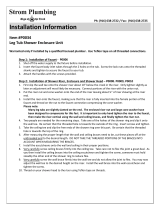
To assure proper positioning in relation to wall, note roughing-in dimensions.
Tome nota de las dimensiones de desbastado para asegurar la posición correcta respecto de la pared.
Pour garantir un bon positionnement par rapport au mur, tenir compte des dimensions de préparation.
ROUGHING-IN DIMENSIONS DIMENSIONES DE DESBASTADO DIMENSIONS DE PRÉPARATION
FINISHED WALL
PARED TERMINADA
PAROI FINIE
BOTTOM OF TUB
FONDO DE LA BAÑERA
FOND BAIGNOIRE
18" OPTIONAL
OPTATIVO, 18" (45,7 cm)
OPTION 45,7 cm (18 po.)
OPTIONAL TO FINISHED FLOOR
USUALLY BETWEEN 65'' AND 78''
OPTATIVO AL PISO TERMINADO,
POR LO GENERAL ENTRE
65" Y 78" (165 A 198 cm)
DISTANCE ENTRE OPTION ET
PLANCHER FINI ENTRE
165 cm ET 198 cm (65 à 78 po.)
"SEE ILLUSTRATION"
"VEA LA FIGURA"
"VOIR ILLUSTRATION"
TOP OF TUB RIM
BORDE SUPERIOR
DE LA BAÑERA
HAUT REBORD
BAIGNOIRE
INLETS 1/2" NPT
ENTRADAS, 1/2"
(12,7 mm) NPT
ENTRÉES 12,7 mm
(1/2 po.)
OUTLETS 1/2" NPT
SALIDA, 1/2"
(12,7 mm) NPT
ORIFICE 12,7 mm
(1/2 po.)
OUTLETS 1/2" NPT
SALIDA, 1/2"
(12,7 mm) NPT
ORIFICE 12,7 mm
(1/2 po.)
3-3/8"
(86 mm)
3-3/8"
(86 mm)
3-3/8"
(86 mm)
THREADED INLETS
ENTRADAS ROSCADAS
ENTRÉES FILETÉES
PRESSURE BALANCE TEMPERATURE CONTROL VALVE
VÁLVULA DE CONTROL DE TEMPERATURA CON EQUILIBRO DE PRESIÓN
ROBINET MITIGEUR
ROUGH VALVE KIT
JUEGO DE VÁVULA SIN ACABADO
ENSEMBLE DE ROBINET ROBUSTE
1/2" COPPER
1/2" (12,7 mm)
COBRE
12,7 mm
(1/2 po.) CUIVRE
See Roughing-in diagram before starting.
Connections are:
1/2" copper sweat for sweat inlets
1/2" female NPT for threaded inlets
Connect RISER PIPE (1) to MANIFOLD (2)
top outlet marked "SHR".
Connect TUB FILLER PIPE (3) at bottom
outlet marked "TUB".
For proper positioning the finished wall
must be within side wall of PLASTER
GUARD (4).
1-5/8" TO 3-1/4"
1-5/8" A 3-1/4" (41 MM A 83 MM)
41 mm (1-5/8 po.) À 83 mm (3-1/4 po.)

M968382A
3
Remove CARTRIDGE (1) by removing
CARTRIDGE SCREWS (2). Remove three
SCREWS (3) from FIXATION RING (4) and
pull out PRESSURE BALANCING (5) unit.
Clean SEALS (9) on base of CARTRIDGE (1).
Check base of PRESSURE BALANCING UNIT (5)
and clean O-RINGS (6). Remove CAPS (7) and
check O-RINGS on inside of CAPS (7). Clean
inside sealing surfaces of VALVE BODY (8).
Re-assemble PRESSURE BALANCING UNIT
(5) and CARTRIDGE (1). Tighten all screws.
VALVE LEAKS WHEN SHUT OFF
BACK TO BACK INSTALLATION
BACK TO BACK INSTALLATION
INSTALACIÓN DORSO CON DORSO
INSTALLATION EN OPPOSITION
ROTATE 180
˚
GIRE 180˚
TOURNER À 180˚
Remove PRESSURE BALANCE UNIT (5).
Remove CAPS (7) and clean valve thoroughly.
Examine balancing unit and check condition
of O-ring on end of piston. Piston should
move back and forth. Order Repair Part
M952100 if balancing unit is defective.
Replace CAPS (7) and install PRESSURE
BALANCE UNIT (5). Make sure inlets line up
with two holes in bottom of casting. Top
flange should butt-up against top of casting.
Remove PRESSURE BALANCE UNIT (5). Rotate
PRESSURE BALANCE UNIT (5) 180˚ so that the
inlets face up and the large outlet port faces
down.
Push PRESSURE BALANCE UNIT (5) in casting
making sure inlets line up with holes in bottom
of casting. Top flange should butt up against
top of casting.
Reassemble FIXATION RING (4) and
CARTRIDGE (1).
UNABLE TO MAINTAIN CONSTANT
TEMPERATURE
5
2
9
1
5
7
8
6
4
3
INLETS
ENTRADAS
ENTRÉES
LARGE OUTLET
SALIDA GRANDE
GROS ORIFICE
Extraiga el CARTUCHO (1) quitando los
TORNILLOS DEL CARTUCHO (2). Quite los tres
tornillos del ANILLO DE RETENCIÓN (4) y saque
la UNIDAD DE EQUILIBRIO DE PRESIÓN (5).
Limpie los SELLOS (9) de la base del CARTUCHO
(1). Revise la base de la UNIDAD DE EQUILIBRIO
DE PRESIÓN (5) y limpie las JUNTAS TÓRICAS
del interior de los TAPONES (7). Limpie las
superficies de sellado interiores del CUERPO DE
LA VÁLVULA (8).
Vuelva a armar la UNIDAD DE EQUILIBRIO DE
PRESIÓN (5) y el CARTUCHO (1). Apriete todos
los tornillos.
FUGAS DE LA VÁLVULA AL ESTAR CERRADA
INSTALACIÓN DORSO CON DORSO
Quite la UNIDAD DE EQUILIBRIO DE PRESIÓN (5).
Quite los TAPONES (7) y limpie la válvula
minuciosamente.
Revise la unidad de equilibrio de presión y el
estado de la junta tórica en el extremo del pistón.
El pistón debe moverse hacia adelante y hacia
atrás. Ordene la pieza de reparación M952100
si la unidad de equilibrio de presión está
defectuosa.Vuelva a colocar los TAPONES (7) y
la UNIDAD DE EQUILIBRIO DE PRESIÓN (5).
Compruebe que las entradas estén alineadas con
los dos orificios en la parte inferior de la pieza
fundida. La brida superior debe quedar apoyada
contra la parte superior de la pieza fundida.
Quite la UNIDAD DE EQUILIBRIO DE PRESIÓN (5).
Gire la UNIDAD DE EQUILIBRIO DE PRESIÓN (5)
180 grados para que las entradas queden hacia
arriba y el orificio de salida grande quede hacia
abajo.
Introduzca la UNIDAD DE EQUILIBRIO DE PRESIÓN
(5) en la pieza fundida, asegurándose de que las
entradas queden alineadas con los orificios en la
parte inferior de la pieza. La brida superior debe
quedar apoyada contra la parte superior de la
pieza fundida.
Vuelva a armar el ANILLO DE RETENCIÓN (4) y el
CARTUCHO (1).
NO PUEDE MANTENERSE UNA
TEMPERATURA CONSTANTE
Enlever la CARTOUCHE (1) en enlevant les VIS
DE CARTOUCHE (2). Enlever les trois VIS (3) de
la BAGUE DE FIXATION (4) et sortir l'unité
d'ÉQUILIBRAGE DE PRESSION (5).
Nettoyer les JOINTS D'ÉTANCHÉITÉ (9) à la base
de la CARTOUCHE (1). Inspecter la base de l'UNITÉ
D'ÉQUILIBRAGE DE PRESSION (5) et nettoyer les
JOINTS TORIQUES (6). Enlever les CAPUCHONS
(7) et inspecter les JOINTS TORIQUES à
l'intérieur des CAPUCHONS (7). Nettoyer les
surfaces d'étanchéité internes du CORPS DE
ROBINET (8).
Remonter l'UNITÉ D'ÉQUILIBRAGE DE PRESSION
(5) et la CARTOUCHE (1). Serrer toutes les vis.
LE ROBINET FUIT LORSQU'IL EST FERMÉ
INSTALLATION EN OPPOSITION
Enlever l'UNITÉ D'ÉQUILIBRAGE DE PRESSION (5).
Enlever les CAPUCHONS (7) et nettoyer
soigneusement le robinet.
Examiner l'unité d'équilibrage et inspecter l'état
des joints toriques au bout du piston. Le piston
doit pouvoir se déplacer d'avant en arrière.
Commander la pièce de réparation M952100
si l'unité d'équilibrage est défectueuse.
Remettre en place les CAPUCHONS (7) et
installer l'UNITÉ D'ÉQUILIBRAGE DE PRESSION
(5). S'assurer que les entrées soient dans
l'alignement des deux trous au fond de la pièce
moulée. La bride supérieure doit être en butée
contre le haut de la pièce moulée.
Enlever l'UNITÉ D'ÉQUILIBRAGE DE PRESSION (5).
Tourner l'UNITÉ D'ÉQUILIBRAGE DE PRESSION
(5) de 180° de façon que les entrées pointent
vers le haut et que le gros orifice de sortie
pointe vers le bas.
Pousser l'UNITÉ D'ÉQUILIBRAGE DE PRESSION
(5) dans la pièce moulée, en s'assurant que les
entrées soient dans l'alignement des trous dans
le fond de la pièce moulée. La bride supérieure
doit être en butée contre le haut de la pièce
moulée.
Remonter la BAGUE DE FIXATION (4) et la
CARTOUCHE (1).
INCAPABLE DE MAINTENIR LA
TEMPÉRATURE CONSTANTE
/