Kohler K-527-1CP Installation guide
- Category
- Storage chests & cabinets & trunks
- Type
- Installation guide
Page is loading ...

IMPORTANT INSTRUCTIONS
WARNING: When using electrical products, basic precautions should always be followed,
including the following:
WARNING: Risk of electric shock. Connect only to circuits protected by a Ground-Fault
Circuit-Interrupter (GFCI) or Residual Current Device (RCD). Grounding is required. The unit
should be installed and grounded by a qualified service representative.
WARNING: Risk of electric shock. A licensed electrician should route all electrical wiring.
WARNING: Risk of electric shock. Disconnect power before servicing.
WARNING: Risk of injury or property damage. Please read all instructions thoroughly before
beginning installation.
NOTICE: Follow all plumbing, electrical, and building codes.
1143086-2-D 2 Kohler Co.

Specifications
Interface
Ambient Temperature Max 125°F (51.5°C)
Maximum Relative Humidity 100% condensing (External surface only)
User Interface Cable Length 20’ (6.1 m)
Valve
Ambient Temperature Greater than 34°F (1°C), Max 104°F (40°C)
Maximum Relative Humidity 95% non-condensing
Electrical Service 120 V, 15 A, 60 Hz
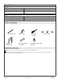
Tools and Materials
Before You Begin
Observe all local plumbing, building, and electrical codes.
Read these instructions and determine all required components along with their installation
locations before beginning this installation.
Pencil Level
Drill and 1/4" Drill Bit
Tape Measure Phillips
Screwdriver
1-3/8" or 35 mm
Hole Saw
Silicone Sealant
Kohler Co. 3 1143086-2-D

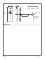
Roughing-In
Cable
3/4"
(19 mm)
20' (6.1 m)
Ø 1-3/8" (35 mm)
18" (457 mm)
7-3/4"
(197 mm)
2-11/16" (68 mm)
Recommended
58" (1473 mm)
To Floor
1143086-2-D 4 Kohler Co.

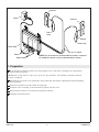
1. Preparation
If not already installed, install the two-outlet digital valve at this time according to the instructions
packed with the product.
NOTE: Your system can be set up to use up to two user interfaces. One interface, installed inside the
shower, is required.
Determine the location of all components along with their installation requirements before beginning
this installation.
Allow for enough slack in the cables for drip loops.
Install the valve according to the instructions packed with the valve.
Route interface cable(s) to the interface installation location.
Complete the finished wall.
Coupler
Drip Loop
Drip
Loop
Power Cord
Outlet
Interface
Interface
20' (6.1 m) Cables
NOTE: Only one interface, installed inside the shower, is required.
An additional interface can be installed outside the shower.
Outlets
Supply Inlets
Kohler Co. 5 1143086-2-D

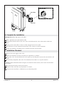
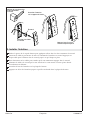
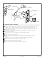
2. Install the Mounting Plate
Determine the interface installation location. The recommended mounting height is 54″ (1372 mm)
from the floor to the bottom of the interface. Refer to the ″Roughing-In″ section.
Hold the mounting plate at the installation location and mark the center hole and two mounting
hole locations onto the wall.
Using a hole saw, cut a 1-3/8″ (35 mm) hole in the finished wall at the marked location.
Using a 1/4″ drill bit, drill holes at the remaining two marked locations.
Press the anchors into the wall.
Generously apply sealant in the groove on the back of the mounting plate.
Pull the cable through the finished wall and the center hole of the mounting plate.
Position the mounting plate on the wall with the tabs on top.
Secure the mounting plate to the wall with the screws.
Apply sealant to cover the mounting plate screws.
Screw
Anchor
1-3/8"
(35 mm) D.
Hole
Mounting Plate
Apply sealant.
Finished Wall
Tabs
Apply sealant.
1143086-2-D 6 Kohler Co.

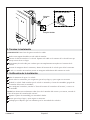
3. Install the Interface
Using the grease from the provided capsule, apply grease into both ends of the coupler.
Connect the cable from the wall and the tail of the interface to the coupler. Press each cable into the
coupler until it clicks into place.
Gently pull on the cables to verify they are fully engaged into the coupler.
Feed the cable and coupler through the hole into the wall cavity. Ensure a drip loop is made.
Hook the top of the interface onto the mounting plate.
Press the bottom of the interface in until it clicks into the mounting plate.
Connect the cables
to the coupler.
Coupler
Press until the interface
clicks into place.
Hook the interface onto
the mounting bracket.
Apply grease in both
ends of the coupler.
Kohler Co. 7 1143086-2-D

4. Complete the Installation
IMPORTANT! Make drip loops in all cables.
Slide a split boot onto each interface cable.
Connect the interface cable to the valve. Press each cable into the valve socket until it clicks into
place.
Gently pull on each cable to verify it is fully engaged in the valve socket.
Press the boot over the connection and into the valve socket to seal the connection.
If only one interface is installed, insert a solid boot into the unused socket.
5. Installation Checkout
Turn on the water supply to the valve.
Check all connections for leaks and make any adjustments as needed.
Plug in the valve. You should hear the valve power up and the power icon on the user interface will
be lit.
If not already completed, refer to the ″User Interface User Guide″ to set up the interface.
NOTE: For more information about using the user interface and its menus, refer to the ″User Interface
User Guide.″
Press the [Power Icon] to turn on the shower.
Check for leaks and make any adjustments as needed.
Verify that the water flow is sufficient for your showering needs.
Slide the split boot onto the
interface cable.
Split Boot
Solid Boot
1143086-2-D 8 Kohler Co.

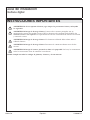
Troubleshooting
CAUTION: Risk of personal injury. The valve may contain hot water; be careful when draining
any residual water.
IMPORTANT! Turn off the power and water supply to the valve before performing any maintenance.
It is recommended that any valve maintenance should be performed by a Kohler Co. Authorized Service
Representative.
This troubleshooting guide is for general aid only. For service and installation issues or concerns, call
1-800-4KOHLER.
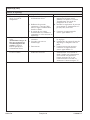
Troubleshooting Table
Symptoms Probable Cause Recommended Action
1. Control panel is not lit. A. Valve is not plugged into the
outlet.
A. Plug the valve into an outlet.
B. Interface cable connections may
be loose or disconnected.
B. Check all interface cable
connections, connect if needed.
C. Circuit breaker has been
tripped.
C. Reset the circuit breaker.
D. The valve memory may require
resetting.
D. Disconnect and reconnect the valve
power cord from the electrical
outlet.
E. A ″straight-through″ cable or
coupler was used to connect the
interface to the valve.
E. Connect the interface to the valve
using a ″cross-over″ cable or
coupler.
F. If none of the recommended
actions for the above issues
correct the symptom, the valve
or interface requires servicing.
F. Contact your Kohler Co.
Authorized Service Representative.
2. The interface power
indicator is lit, but the
system will not turn on.
A. Interface cable connections may
be loose.
A. Check all interface cable
connections, connect if needed.
B. If the above recommended
action does not correct the
symptom, the interface or valve
requires servicing.
B. Contact your Kohler Co.
Authorized Service Representative.
3. The interface functions
normally but no water
flows from the
components.
A. Valve outlets may be blocked. A. Check the valve outlets for
blockage or debris. Clean the outlet
screens. Refer to the ″Clean the
Outlet Screens″ section in the Valve
Homeowners Guide.
B. Fittings/Spray faces may be
blocked.
B. Clean the spray faces and any
screens in your fittings.
C. Hot and cold water supplies are
not turned on.
C. Turn on the water supply to the
valve.
D. The valve memory may require
resetting.
D. Disconnect and reconnect the valve
power cord from the electrical
outlet.
E. System error. E. Check the user interface for an
error code. Refer to the ″Error Code
Diagnosis
″ section in the Digital
Interface Homeowners or User
Guide.
F. If none of the recommended
actions for the above issues
correct the symptom, the valve
requires servicing.
F. Contact your Kohler Co.
Authorized Service Representative.
4. Maximum blend
temperature too hot or
too cold.
A. Incorrect maximum temperature
setting.
A. Refer to the ″Set the Maximum
Temperature″ section in the Digital
Interface User Guide.
Kohler Co. 9 1143086-2-D

Troubleshooting (cont.)
Troubleshooting Table
Symptoms Probable Cause Recommended Action
B. If the above recommended
action does not correct the
symptom, the interface or valve
requires servicing.
B. Contact your Kohler Co.
Authorized Service Representative.
5. Continuous flow. A. System will not switch off. A. Turn off the water and power
supply and contact your Kohler Co.
Authorized Service Representative.
6. Only cold water flows
from the outlets.
A. Hot water supply is either not
turned on or not connected to
the valve inlet.
A. Check if the hot water supply is
turned on and connected to the
valve inlet.
B. Hot water inlet is blocked. B. Check the hot water inlet screen for
blockage. Clean or replace the inlet
screen. Refer to the Valve
Homeowners Guide.
C. The hot water supply is
exhausted.
C. Allow time for the water heater to
come up to temperature.
D. If none of the recommended
actions for the above issues
correct the symptom, the valve
requires servicing.
D. Contact your Kohler Co.
Authorized Service Representative.
7. Fluctuating or reduced
flow rate. Valve is
functioning properly.
A. Valve inlets may be blocked. A. Check the valve inlets for blockage
or debris. Clean the inlet screens.
Refer to the ″Clean the Inlet
Screens″ section in the Valve
Homeowners Guide.
B. Fittings/Spray faces may be
blocked.
B. Clean the spray faces and any
screens in your fittings.
C. Water outlet pressure is low. C. Check that the flow rate is at or
above the minimum rate required.
Refer to ″Specifications″ section in
the Valve Homeowners Guide.
D. Fluctuating supply pressure. D. Verify that the dynamic inlet
pressures are within specifications.
Refer to ″Specifications″ section in
the Valve Homeowners Guide.
E. Water supply temperatures are
not within the recommended
range.
E. Check if inlet water temperatures
are within the recommended range.
8. Blend temperature drift or
temperature cycling.
A. Fluctuating water supply
temperature.
A. Check the inlet temperature
differentials and verify they are
sufficient. Refer to ″Specifications″
section in the Valve Homeowners
Guide.
B.
Pressure difference greater than
5 psi (34.5 kPa) between the hot
and cold supply lines.
B. Install pressure regulators to bring
the supplies within 5 psi (34.5 kPa)
of each other.
C. If none of the recommended
actions for the above issues
correct the symptom, the valve
requires servicing.
C. Contact your Kohler Co.
Authorized Service Representative.
1143086-2-D 10 Kohler Co.

Troubleshooting (cont.)
Troubleshooting Table
Symptoms Probable Cause Recommended Action
9. Water leaking from the
valve.
CAUTION: Risk of
personal injury or
product damage. Turn off
the main power and
water supply.
A. Connections are not secure. A. Check all connections. Make
adjustments as needed.
B. Seals are worn or damaged. B. Order a seal service pack and
replace all seals.
C. Internal leak. C. Unit requires overhaul. Contact
your Kohler Co. Authorized Service
Representative.
10. Hot water only, the valve
shuts down.
A. Hot and cold lines are reversed. A. Switch hot and cold water supply
connections. Verify the hot water
supply is connected to the inlet
marked ″H″ and the cold water
supply is connected to the inlet
marked ″C.″
Kohler Co. 11 1143086-2-D
Page is loading ...
Page is loading ...
Page is loading ...
Page is loading ...
Page is loading ...
Page is loading ...
Page is loading ...
Page is loading ...
Page is loading ...
Page is loading ...
Page is loading ...
Page is loading ...
Page is loading ...
Page is loading ...
Page is loading ...
Page is loading ...
Page is loading ...
Page is loading ...
Page is loading ...
Page is loading ...
Page is loading ...
-
 1
1
-
 2
2
-
 3
3
-
 4
4
-
 5
5
-
 6
6
-
 7
7
-
 8
8
-
 9
9
-
 10
10
-
 11
11
-
 12
12
-
 13
13
-
 14
14
-
 15
15
-
 16
16
-
 17
17
-
 18
18
-
 19
19
-
 20
20
-
 21
21
-
 22
22
-
 23
23
-
 24
24
-
 25
25
-
 26
26
-
 27
27
-
 28
28
-
 29
29
-
 30
30
-
 31
31
-
 32
32


Kohler K-527-1CP Installation guide
- Category
- Storage chests & cabinets & trunks
- Type
- Installation guide
Ask a question and I''ll find the answer in the document
Finding information in a document is now easier with AI
in other languages
- français: Kohler K-527-1CP Guide d'installation
- español: Kohler K-527-1CP Guía de instalación
Related papers
-
Kohler K-558 User manual
-
Kohler 558-1CP Installation guide
-
Kohler 558-1CP Installation guide
-
-
Kohler 99693-P-NA Installation guide
-
-
-
-
-