Page is loading ...
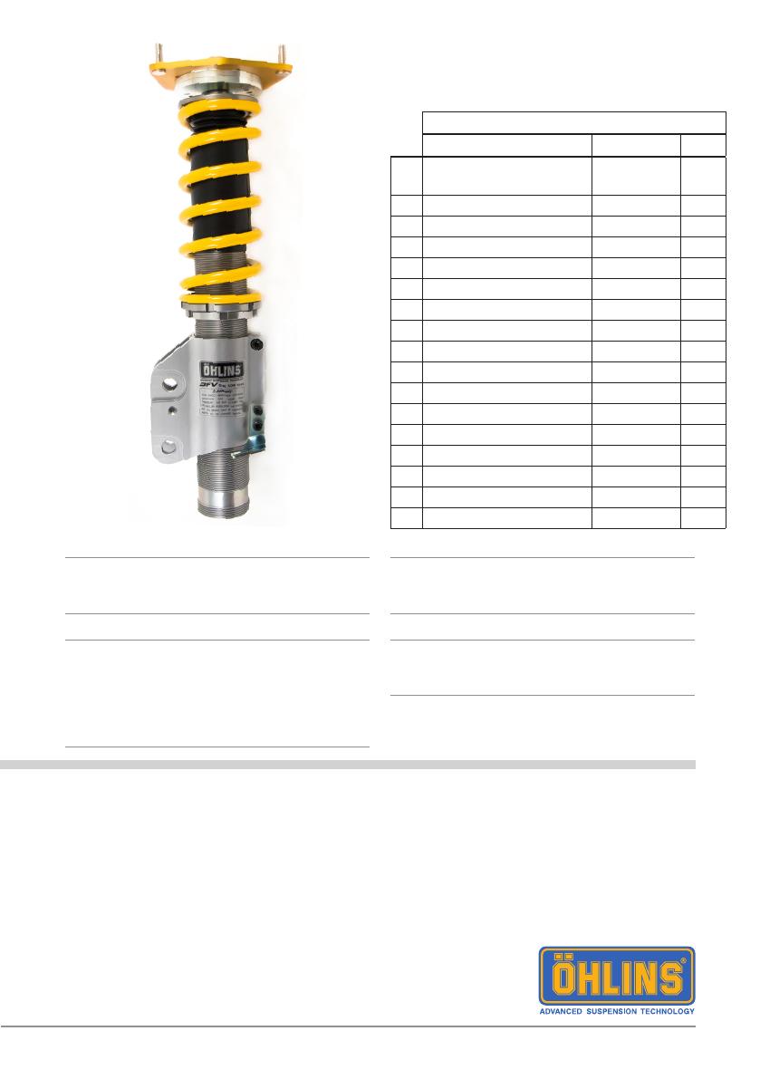
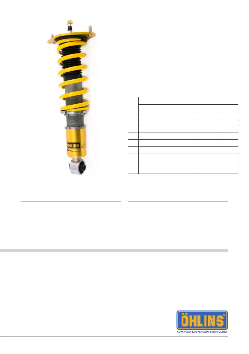
Shock Absorber Kit for Subaru BRZ (ZC6 & ZD8),
Toyota GT86 (ZN6/ZN7) & Toyota GR86 (ZN8), Scion FR-S
SUS MP21S2
front
Mounting Instructions
Note! 1
Please note that there can be small differences
between your product and the images in
these instructions.
Note! 1
Please note that during storage and transport,
especially at high ambient temperature, some
of the oil and grease used for assembly may
leak and stain the packaging. This will not cause
damage to the product, wipe off the excessive
oil or grease with a cloth.
Note! 1
Before you install this product, check the kit
contents. If anything is missing, please contact
an Öhlins dealer.
Warning! ⚠
Before you install this product, read the Öhlins
Owner’s manual. This product is an important
part of the vehicle and the vehicle stability.
Kit Contents
Description Part No Pcs
1 Shock absorber SUS 1P20
& 2P20
2
2 Dust boot 10216-02 2
3 Plastic spring spacer 25602-01 2
4 Spring 47010-15 2
5 Rubber spring spacer 25601-01 2
6 Upper spring seat 24637-01 2
7 Spacer 24629-25 2
8 Nut (M12) 95702-12 2
9 ABS cord clamp 24624-01 2
10 Nut ange (M8) 04777-02 2
11 Bolt (M6) 24617-01 2
12 Spacer 2
13 C-spanner 24639-01 1
14 C-spanner 24639-03 1
15 Öhlins sticker kit 10207-01 1
16 Öhlins emblem kit 10207-02 1
17 Öhlins Owners manual 07451-01 1
2
MOUNTING INSTRUCTIONS
Warning!
It is advisable to have an Öhlins dealer install the shock
absorber.
When installing, read your Vehicle Service Manual.
1
Raise the vehicle and put it on jack stands.
Warning! ⚠
Ensure that it is securely supported.
2
Remove the front wheels.
3
Loosen the bolts for the lower strut
attachments.
Caution! ✋
Support the wheel hubs in an appropriate
way on each side of the vehicle so that the
brake hose and/or drive shaft joint can not be
damaged.
4
Loosen the upper attachment. Remove the
original struts from the car.
5
Remove the brake hose brackets from the
standard struts.
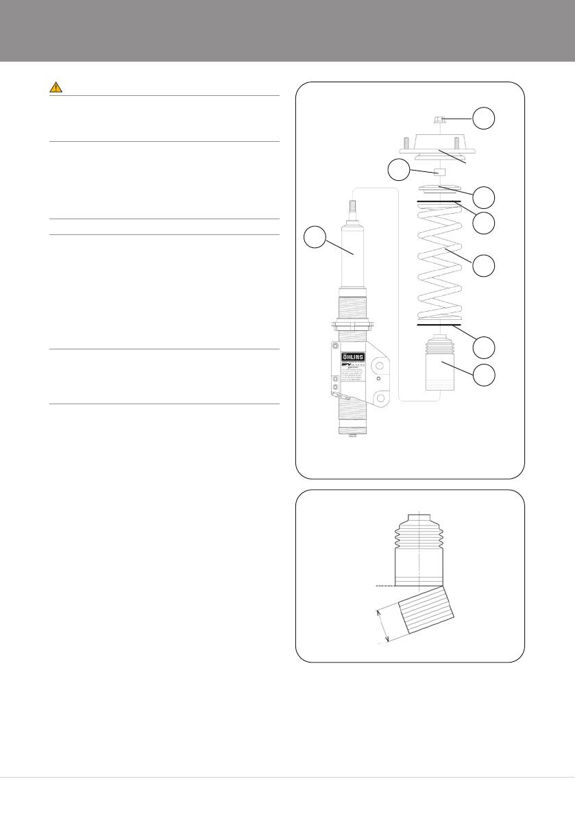
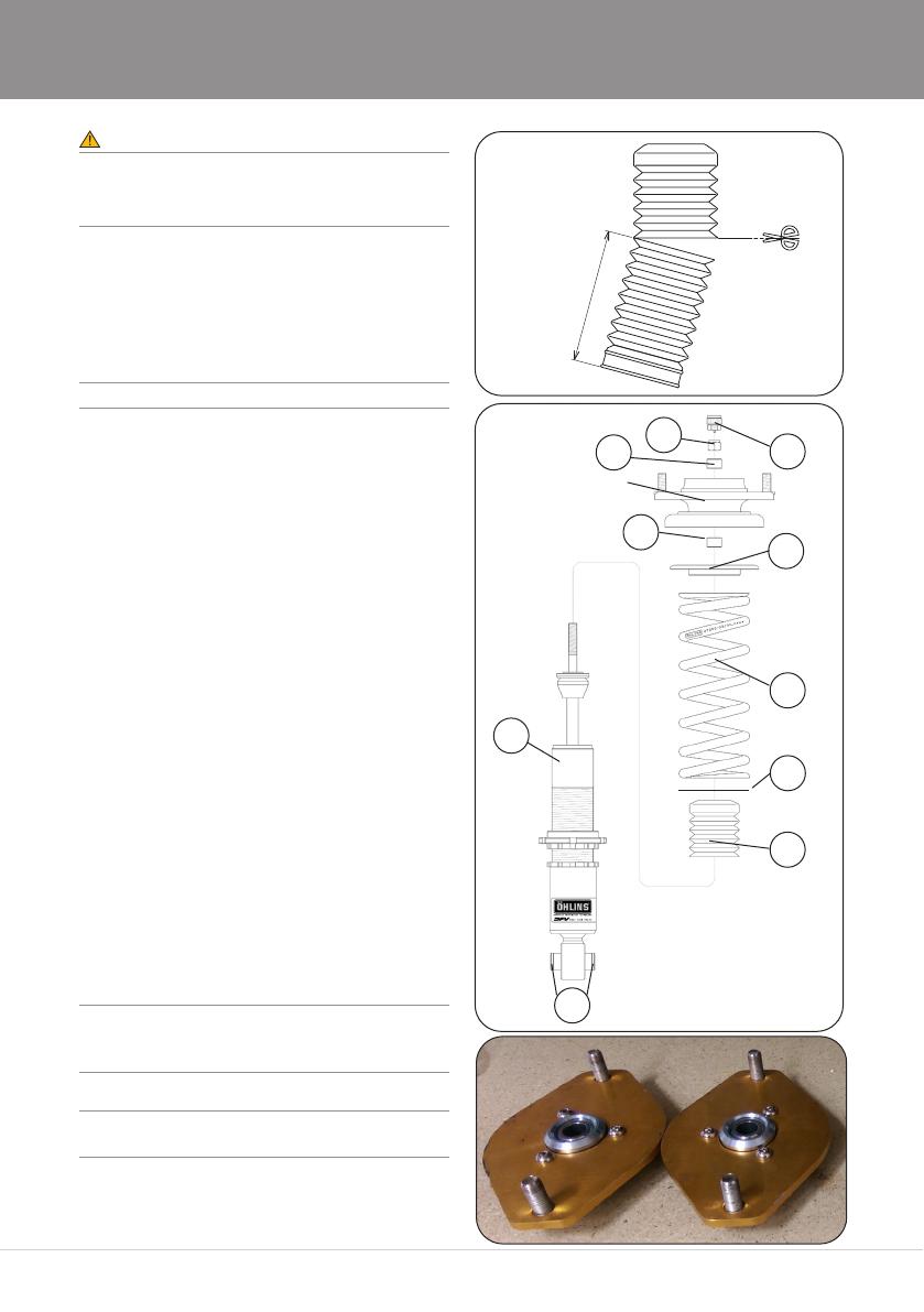
6
Cut the dust boot 20 mm from the lower end
with a pair of scissors according to g 2.
7
Fit the dust boot, the plastic spring spacer, the
spring, the rubber spring spacer and the upper
spring seat to the strut according to g 1. Fit
the top pin spacer, the top mount and the M12
lock nut. Tighten the lock nut to 35 - 40 Nm.
Solid top mount with camber adjustment is
available as option (part number 25633-43 for
left front and 25633-44 for right front (see g 4).
Height of the vehicle is needed to be adjusted
when changing to solid top mounts.
Fig. 1
20 mm
Cut
Original
top mount
8
6
4
7
5
3
2
1
Fig. 2
3
MOUNTING INSTRUCTIONS
Note! 1
When tightening the top mount nut , the shock
absorber shaft must be held in position with a 5
mm Allen key.
8
Install the Öhlins McPherson struts on the
vehicle.
9
Fasten the upper attachments.
10
Raise the wheel hub with a jack to remove the
freeplay of the lower strut attachment bolts
before tightening them.
11
Adjust the preload and lower bracket position
according to g 5. Tighten the lower spring seat
and the lock ring to 50 - 60 Nm).
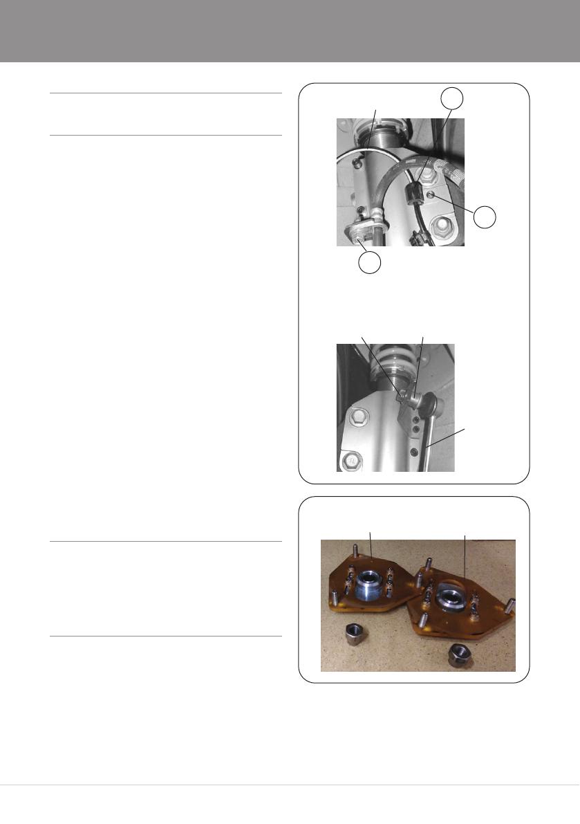
12
Mount the ABS cord clamp to the Öhlins struts.
Tighten the M6 bolts to 6 Nm. Fix the ABS cord
by bending the ABS cord clamp according to
g 3.
13
Tighten the lower bracket Allen bolts to
10-15Nm. Mount the OEM ARB links with the
spacer (10 mm) according to g 3.
Note! 1
Make sure that all bolts are tightened to the
correct torque and that nothing fouls or restricts
movement of the strut when it is being fully
compressed or extended. Test this over the
whole steering range from lock to lock. This
is very important if you have installed an after
market sway bar end link!.
14
Make sure that all removed parts are
reinstalled in the same way as they were
before the installation of the Öhlins shock
absorber.
ABS cord
Original nut Spacer
Stabilizer link
Caution! ✋
Assemble this spacer (10 mm) between
the bracket and the ARB link.
Left front:
25633-43
Right front:
25633-44
9
11
10
Fig. 3
Fig. 4
Öhlins Racing AB
Box 722
S-194 27 Upplands Väsby, Sweden
Phone +46 8 590 025 00
fax +46 8 590 025 80
© Öhlins Racing AB. All rights
reserved. Any reprinting or
unauthorized use without the written
permission of Öhlins Racing AB
is prohibited.
Öhlins products are subject to
continuous improvement and
development, therefore, although
these instructions include the most
up-to-date information available at
the time of printing, minor updates
may occur.
To nd the latest information
contact an Öhlins distributor.
Please contact Öhlins if you have
any questions regarding the
contents in this document.
SETUP DATA
Warning! ⚠
Before you ride/drive, always make sure that the
setup is according to the recommended setup
data. Read about adjustments and setting up
in the Öhlins Owner’s Manual before you make
any adjustments. Contact an Öhlins dealer if you
have any questions about setting up.
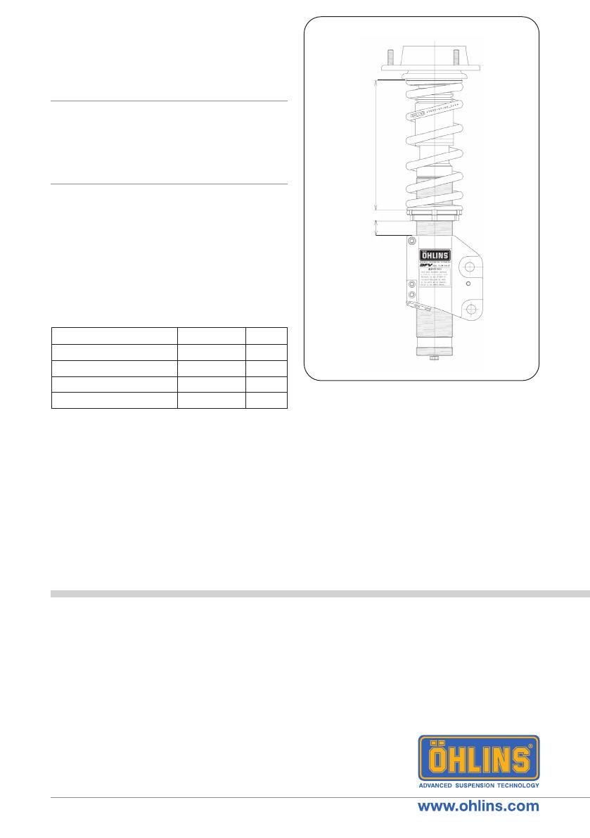
The standard spring preload is 10 mm from a
free length of 200 mm, giving 190 mm installed
length, see g 5.
ADJUSTMENTS
Part no. MI_SUSMP21S2_1
Issued 2023-05-31
Recommended set-up
Click setting
Track 0-7 clicks
Winding road 5-10 clicks
Street 10-20 clicks
Spring preload 10 mm
Recommended spring
47010-15 (60 N/mm)
The actual vehicle height
With the preload and height adjuster in their
recommended position, the vehicle is lowered
approximately -20mm when compared to the
original suspension. Depending on car model
and equipment, the height may vary. The
spring preload adjustment range is 1-15mm.
190 mm25 mm
Fig. 5
Note! 1
Please note that there can be small differences
between your product and the images in
these instructions.
Note! 1
Please note that during storage and transport,
especially at high ambient temperature, some
of the oil and grease used for assembly may
leak and stain the packaging. This will not cause
damage to the product, wipe off the excessive
oil or grease with a cloth.
Note! 1
Before you install this product, check the kit
contents. If anything is missing, please contact
an Öhlins dealer.
Warning! ⚠
Before you install this product, read the Öhlins
Owner’s manual. This product is an important
part of the vehicle and the vehicle stability.
Kit Contents
Description Part No Pcs
1 Shock absorber SUS 6P20 2
2 Dust boot 10216-01 2
3 Rubber spring spacer 25601-01 2
4 Spring 47000-15 2
5 Spring seat 25618-11 2
6 Spacer 24629-26 4
7 Lock nut (M10) 24627-01 2
8 Adjuster 24631-04 2
9 Bushing spacer 24629-06 4
Shock Absorber Kit for Subaru BRZ (ZC6 & ZD8),
Toyota GT86 (ZN6/ZN7) & Toyota GR86 (ZN8), Scion FR-S
SUS MP21S2
rear
Mounting Instructions
6
MOUNTING INSTRUCTIONS
Warning!
It is advisable to have an Öhlins dealer install the shock
absorber.
When installing, read your Vehicle Service Manual.
1
Raise the vehicle and put it on jack stands.
Warning! ⚠
Ensure that it is securely supported.
2
Remove the rear wheels.
3
Remove the lower and the upper attachments
and remove the original shock absorbers.
4
Cut the dust boot 70mm from the lower end
with a pair of scissors according to g 1.
5
Tighten the lower spring seat and the lock ring
to 50 - 60 Nm.
Fit the two bushing spacers, the dust boot, the
spring, plastic seat, the top mount, the spacer
and the Lock nut according to g 2. Tighten
the lock nut to 20 Nm. Fit the adjuster to the
damper according to g 2.
Solid top mount is available as option (part
number 25633-45 see g 3). Note that you
need two pieces for one car. Height of the
vehicle is needed to be reset when changing to
solid top mounts.
Note! 1
When tightening the top mount nut, the shock
absorber shaft must be held in position with a 4
mm Allen key.
Note! 1
For one kit you need two top mounts with
bearings.
Original
top mount
70 mm
2
4
5
8
7
6
6
9
1
3
Fig. 1
Fig. 2
Fig. 3
7
MOUNTING INSTRUCTIONS
6
Install the Öhlins shock absorbers on the
vehicle.
7
Fasten the upper attachments.
Note! 1
Make sure that all bolts are tightened to the
correct torque and that nothing fouls or restricts
movement of the absorber when it is being fully
compressed or extended.
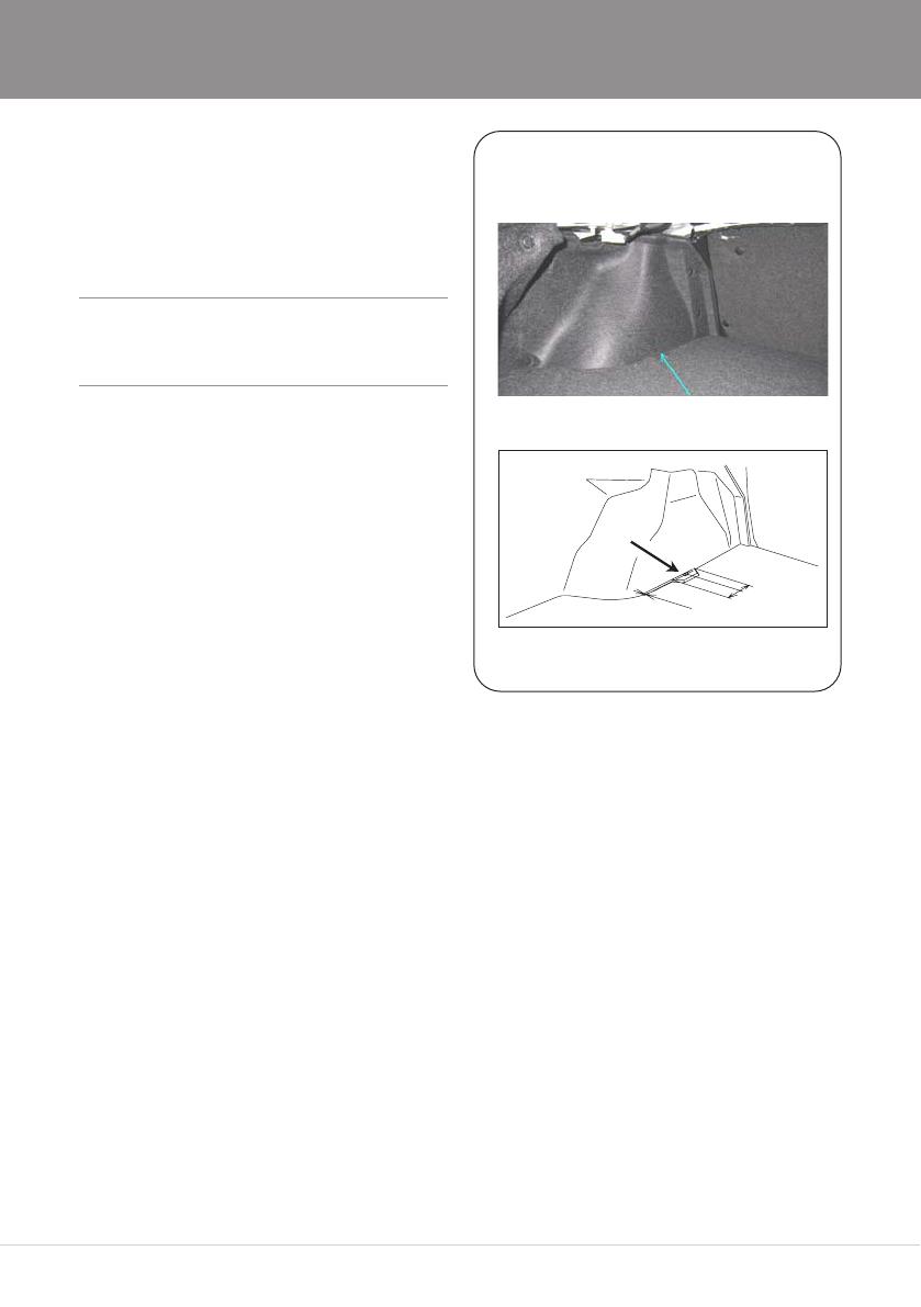
8 - Optional
For easier access to the adjuster, drill a Ø20
hole in the side panel according to g 4, and
install the adjuster.
9
Make sure that all removed parts are
reinstalled in the same way as they were
before the installation of the Öhlins shock
absorber.
10mm
Left side of vehicle body inside trunk room.
Make a Ø20 mm hole in the side panel in
the shown position.
Make a Ø20 mm hole in the center of the
lip.
Fig. 4

Öhlins Racing AB
Box 722
S-194 27 Upplands Väsby, Sweden
Phone +46 8 590 025 00
fax +46 8 590 025 80
© Öhlins Racing AB. All rights
reserved. Any reprinting or
unauthorized use without the written
permission of Öhlins Racing AB
is prohibited.
Öhlins products are subject to
continuous improvement and
development, therefore, although
these instructions include the most
up-to-date information available at
the time of printing, minor updates
may occur.
To nd the latest information
contact an Öhlins distributor.
Please contact Öhlins if you have
any questions regarding the
contents in this document.
SETUP DATA
Warning! ⚠
Before you ride/drive, always make sure that the
setup is according to the recommended setup
data. Read about adjustments and setting up
in the Öhlins Owner’s Manual before you make
any adjustments. Contact an Öhlins dealer if you
have any questions about setting up.
The standard spring preload is 6mm from a
free length of 180mm, giving 174 mm installed
length, see g 5.
Part no. MI_SUSMP21S2_1
Issued 2023-05-31
Recommended set-up
Click setting
Track 0-7 clicks
Winding road 5-10 clicks
Street 10-20 clicks
Spring preload 6 mm
Recommended spring
47000-15 (60 N/mm)
The actual vehicle height
With the preload and height adjuster in their
recommended position, the vehicle is lowered
approximately -20mm when compared to the
original suspension. Depending on car model
and equipment, the height may vary. The
spring preload adjustment range is 1-15 mm.
174 mm
25 mm
ADJUSTMENTS
Fig. 5
/