Page is loading ...

OWNER'S MANUAL
(FOR MODELS MANUFACTURED 07/14)
MODEL W1834
UNIVERSAL
KNIFE GRINDER
Phone: (360) 734-3482 • Online Technical Support: [email protected]
COPYRIGHT ©NOVEMBER, 2014 BY WOODSTOCK INTERNATIONAL, INC.
WARNING: NO PORTION OF THIS MANUAL MAY BE REPRODUCED IN ANY SHAPE OR FORM WITHOUT
THE WRITTEN APPROVAL OF WOODSTOCK INTERNATIONAL, INC.
#AW15415 Printed in Taiwan
177335

This manual provides critical safety instructions on the proper setup,
operation, maintenance, and service of this machine/tool. Save this
document, refer to it often, and use it to instruct other operators.
Failure to read, understand and follow the instructions in this manual
may result in fire or serious personal injury—including amputation,
electrocution, or death.
The owner of this machine/tool is solely responsible for its safe use.
This responsibility includes but is not limited to proper installation in
a safe environment, personnel training and usage authorization,
proper inspection and maintenance, manual availability and compre-
hension, application of safety devices, cutting/sanding/grinding tool
integrity, and the usage of personal protective equipment.
The manufacturer will not be held liable for injury or property
damage from negligence, improper training, machine modifications or
misuse.
Some dust created by power sanding, sawing, grinding, drilling, and
other construction activities contains chemicals known to the State of
California to cause cancer, birth defects or other reproductive harm.
Some examples of these chemicals are:
• Lead from lead-based paints.
• Crystalline silica from bricks, cement and other masonry products.
• Arsenic and chromium from chemically-treated lumber.
Your risk from these exposures varies, depending on how often you
do this type of work. To reduce your exposure to these chemicals:
Work in a well ventilated area, and work with approved safety equip-
ment, such as those dust masks that are specially designed to filter
out microscopic particles.

SET UPELECTRICAL MAINTENANCE
SERVICE PARTS
OPERATIONS
SAFETYINTRODUCTION
USE THE QUICK GUIDE PAGE LABELS TO SEARCH OUT INFORMATION FAST!
INTRODUCTION .....................................2
Woodstock Technical Support .................. 2
Machine Data Sheet .............................. 3
Controls and Features ........................... 5
SAFETY ...............................................6
Standard Machinery Safety Instructions ...... 6
Additional Safety Instructions for Grinders .. 8
ELECTRICAL .........................................9
Circuit Requirements ............................ 9
Grounding Requirements ...................... 10
Extension Cords ................................ 10
SETUP .............................................. 11
Unpacking ....................................... 11
Inventory ........................................ 11
Cleaning Machine ............................... 12
Machine Placement ............................ 13
Mounting ......................................... 13
Bench Mounting................................. 13
Test Run .......................................... 14
OPERATIONS....................................... 15
General .......................................... 15
Grinding Tips .................................... 16
Wheel Selection ................................ 17
Wheel Care ...................................... 17
Wheel Inspection & Ring Test ................ 18
Mounting Pivot Support ....................... 19
Sharpening Narrow Tools ...................... 20
Sharpening Wide Knives ....................... 21
Contents
MAINTENANCE .................................... 25
General .......................................... 25
Cleaning ......................................... 25
Lubrication ...................................... 25
Wheel Dressing ................................. 26
Wheel Replacement............................ 27
SERVICE ............................................ 28
Troubleshooting ................................. 28
Electrical Safety Instructions ................. 30
Wiring Diagram ................................. 31
PARTS .............................................. 32
Main .............................................. 32
Main Parts List .................................. 33
Labels & Cosmetics ............................ 34
WARRANTY ........................................ 37

-2-
Model W1834 (For Machines Mfd. Since 7/14)
INTRODUCTION
Woodstock Technical Support
Woodstock International, Inc. is committed to customer satisfaction. Our intent with this manual is to
include the basic information for safety, setup, operation, maintenance, and service of this product.
In the event that questions arise about your machine, please contact Woodstock International Technical
Support at (360) 734-3482 or send e-mail to: tech-support@shopfox.biz. Our knowledgeable staff will
help you troubleshoot problems or process warranty claims.
INTRODUCTION
If you need the latest edition of this manual, you can download it from http://www.shopfox.biz.
If you have comments about this manual, please contact us at:
Woodstock International, Inc.
Attn: Technical Documentation Manager
P.O. Box 2309
Bellingham, WA 98227
Email: manuals@woodstockint.com

-3-
Model W1834 (For Machines Mfd. Since 7/14)
INTRODUCTION
MODEL W1834
20" BLADE GRINDER
Model W1834 Machine Specifications, Page 1 of 2
© Woodstock International, Inc. • Phone #: (800) 840-8420 • Web: www.shopfox.biz
MACHINE
SPECIFICATIONS
Product Dimensions:
Weight ................................................................................................................... 45 lbs.
Width (side-to-side) x Depth (front-to-back) x Height .............................................. 24 x 11
1
⁄2 x 13 in.
Foot Print (Length x Width) .................................................................................. 9 in. Diameter
Shipping Dimensions:
Type ................................................................................................................... Cardboard
Content ..................................................................................................................Machine
Total Shipping Weight ...................................................................................................59 lbs.
Box 1 Length/Width/Height .................................................................................20 x 13 x 13 in.
Box 2 Length/Width/Height ................................................................................... 26 x 5 x 3 in.
Electrical:
Power Requirement..............................................................................
110V, Single-Phase, 60 Hz
Full-Load Current Rating ....................................................................................................
3A
Minimum Circuit Size .......................................................................................................
15A
Switch ..........................................................................................................
ON/OFF Toggle
Switch Voltage ............................................................................................................. 110V
Cord Length ................................................................................................................. 4 ft.
Cord Gauge ..............................................................................................................
16 AWG
Plug Included ................................................................................................................. Ye s
Included Plug Type .................................................................................................
NEMA 5-15
Motors:
Main
Type ................................................................................... TEFC Capacitor Start Induction
Horsepower ........................................................................................................
1
⁄2
HP
Voltage ................................................................................................................ 110V
Phase ................................................................................................................ Single
Amps .....................................................................................................................
3A
Speed ............................................................................................................ 3500 RPM
Cycle ................................................................................................................. 60 Hz
Number Of Speeds ...................................................................................................... 1
Power Transfer .............................................................................................. Direct Drive
Bearings ............................................................................
Shielded and Permanently Sealed
Capacities:
Maximum Blade Length ..................................................................................................20 in.
Table Tilt ........................................................................................................... 20 – 70 deg.
Grinding Wheel Specifications:
Type ........................................................................................................................
Type 5
Diameter .................................................................................................................... 6 in.
Thickness ................................................................................................................. 1
1
⁄2 in.
Bore ........................................................................................................................
1
⁄2 in.

-4-
Model W1834 (For Machines Mfd. Since 7/14)
INTRODUCTION
Construction
Base ..................................................................................................................... Cast Iron
Table .................................................................................................................... Cast Iron
Other Specifications
Country of Origin ....................................................................................................... Taiwan
Warranty ................................................................................................................. 2 Years
Serial Number Location ........................................................................ ID Label on Front of Motor
Assembly Time .........................................................................................................
1
⁄2 Hour
CSA Certified ................................................................................................................. Yes
Features:
Knife Holder Adjusts from 20° – 70°
120 Grit Aluminum Oxide Grinding Stone with Adjustable Elevation Control
Model W1834 Machine Specifications, Page 2 of 2

-5-
Model W1834 (For Machines Mfd. Since 7/14)
INTRODUCTION
Controls and Features
Knife
Clamp
Screw
Knife
Clamp
Wheel
Guard
Table
Handwheel
Table
Grinding
Wheel
Slide
Table
Mounting
Hole
ON/OFF
Switch
Pivot Support
Adjustment
Knob
Table
Lock
Pivot
Support
Slide
Bar
Knife
Adjustment
Screw
Figure 1. Model W1834 identification.

-6-
Model W1834 (For Machines Mfd. Since 7/14)
SAFETY
SAFETY
Indicates a potentially hazardous situation which, if not avoided,
MAY result in minor or moderate injury.
Indicates an imminently hazardous situation which, if not avoided,
WILL result in death or serious injury.
Indicates a potentially hazardous situation which, if not avoided,
COULD result in death or serious injury.
This symbol is used to alert the user to useful information about
proper operation of the equipment or a situation that may cause
damage to the machinery.
NOTICE
SAFETY
OWNER’S MANUAL. Read and understand this
owner’s manual BEFORE using machine.
TRAINED OPERATORS ONLY. Untrained operators
have a higher risk of being hurt or killed. Only
allow trained/supervised people to use this
machine. When machine is not being used,
disconnect power, remove switch keys, or
lock-out machine to prevent unauthorized
use—especially around children. Make
workshop kid proof!
DANGEROUS ENVIRONMENTS. Do not use
machinery in areas that are wet, cluttered,
or have poor lighting. Operating machinery
in these areas greatly increases the risk of
accidents and injury.
MENTAL ALERTNESS REQUIRED. Full mental
alertness is required for safe operation of
machinery. Never operate under the influence
of drugs or alcohol, when tired, or when
distracted.
ELECTRICAL EQUIPMENT INJURY RISKS. You can
be shocked, burned, or killed by touching live
electrical components or improperly grounded
machinery. To reduce this risk, only allow an
electrician or qualified service personnel to
do electrical installation or repair work, and
always disconnect power before accessing or
exposing electrical equipment.
DISCONNECT POWER FIRST. Always disconnect
machine from power supply BEFORE making
adjustments, changing tooling, or servicing
machine. This eliminates the risk of injury
from unintended startup or contact with live
electrical components.
EYE PROTECTION. Always wear ANSI-approved
safety glasses or a face shield when operating
or observing machinery to reduce the risk of
eye injury or blindness from flying particles.
Everyday eyeglasses are not approved safety
glasses.
Standard Machinery Safety Instructions
For Your Own Safety,
Read Manual Before Operating Machine
The purpose of safety symbols is to attract your attention to possible hazardous conditions. This
manual uses a series of symbols and signal words intended to convey the level of importance of the
safety messages. The progression of symbols is described below. Remember that safety messages by
themselves do not eliminate danger and are not a substitute for proper accident prevention mea-
sures—this responsibility is ultimately up to the operator!
Standard Machinery Safety Instructions

-7-
Model W1834 (For Machines Mfd. Since 7/14)
SAFETY
WEARING PROPER APPAREL. Do not wear
clothing, apparel, or jewelry that can become
entangled in moving parts. Always tie back
or cover long hair. Wear non-slip footwear to
avoid accidental slips, which could cause loss
of workpiece control.
HAZARDOUS
DUST. Dust created while using
machinery may cause cancer, birth defects,
or long-term respiratory damage. Be aware of
dust hazards associated with each workpiece
material, and always wear a NIOSH-approved
respirator to reduce your risk.
HEARING PROTECTION.
Always wear hearing
protection when operating or observing
loud machinery. Extended exposure to this
noise without hearing protection can cause
permanent hearing loss.
REMOVE ADJUSTING TOOLS.
Tools left on
machinery can become dangerous projectiles
upon startup. Never leave chuck keys,
wrenches, or any other tools on machine.
Always verify removal before starting!
INTENDED USAGE.
Only use machine for its
intended purpose—never make modifications
without prior approval from Woodstock
International. Modifying machine or using
it differently than intended will void the
warranty and may result in malfunction or
mechanical failure that leads to serious
personal injury or death!
AWKWARD POSITIONS.
Keep proper footing and
balance at all times when operating machine.
Do not overreach! Avoid awkward hand
positions that make workpiece control difficult
or increase the risk of accidental injury.
CHILDREN & BYSTANDERS.
Keep children and
bystanders at a safe distance from the work
area. Stop using machine if they become a
distraction.
GUARDS & COVERS.
Guards and covers reduce
accidental contact with moving parts or flying
debris—make sure they are properly installed,
undamaged, and working correctly.
FORCING MACHINERY. Do not force machine. It
will do the job safer and better at the rate for
which it was designed.
NEVER STAND ON MACHINE. Serious injury may
occur if machine is tipped or if the cutting
tool is unintentionally contacted.
STABLE MACHINE. Unexpected movement during
operation greatly increases risk of injury or
loss of control. Before starting, verify machine
is stable and mobile base (if used) is locked.
USE RECOMMENDED ACCESSORIES. Consult
this owner’s manual or the manufacturer for
recommended accessories. Using improper
accessories will increase risk of serious injury.
UNATTENDED OPERATION. To reduce the risk
of accidental injury, turn machine OFF and
ensure all moving parts completely stop
before walking away. Never leave machine
running while unattended.
MAINTAIN WITH CARE. Follow all maintenance
instructions and lubrication schedules to
keep machine in good working condition. A
machine that is improperly maintained could
malfunction, leading to serious personal injury
or death.
CHECK DAMAGED PARTS. Regularly inspect
machine for any condition that may affect
safe operation. Immediately repair or replace
damaged or mis-adjusted parts before
operating machine.
MAINTAIN POWER CORDS. When disconnecting
cord-connected machines from power, grab
and pull the plug—NOT the cord. Pulling the
cord may damage the wires inside, resulting
in a short. Do not handle cord/plug with wet
hands. Avoid cord damage by keeping it away
from heated surfaces, high traffic areas, harsh
chemicals, and wet/damp locations.
EXPERIENCING DIFFICULTIES. If at any time
you experience difficulties performing the
intended operation, stop using the machine!
Contact Technical Support at (360) 734-3482.

-8-
Model W1834 (For Machines Mfd. Since 7/14)
SAFETY
Additional Safety Instructions for Grinders
USE this and other machinery with caution
and respect. Always consider safety first,
as it applies to your individual working con-
ditions. No list of safety guidelines can be
complete—every shop environment is differ-
ent. Failure to follow guidelines could result
in serious personal injury, damage to equip-
ment or poor work results.
READ and understand this
entire manual before using
this machine. Serious per-
sonal injury may occur
if safety and operational
information is not under-
stood and followed. DO
NOT risk your safety by not
reading!
EYE PROTECTION. Grinding causes small par-
ticles to become airborne at a high rate of
speed. ALWAYS wear safety glasses or face
shield when using this machine.
STARTING GRINDER. If a grinding wheel is
damaged, it will usually fly apart shortly
after start-up. Never start the grinder with
the wheel above the surface of the grinder
table. Stand clear of the grinder after
starting it and wait for at least one minute
before standing in front of it.
MOUNTING TO WORKBENCH. An unsecured
grinder may become dangerously out of
control during operation. Make sure the
grinder is FIRMLY secured to the workbench.
WHEEL SPEED RATING. Wheels operated at a
faster speed than rated may fly apart during
use. Before mounting a new wheel, be sure
the wheel RPM rating is equal to or higher
than the speed of the grinder—3500 RPM.
WHEEL FLANGES. Only use the wheel flanges that
are included with this grinder when mounting
wheels. Other flanges may not properly secure
the wheel and will increase the risk of the
wheel flying apart during operation.
WHEEL INSPECTION. Visually inspect the wheel
and perform the “ring test” before installation
to ensure that it is safe to use. A wheel that
does not pass the ring test may fly apart during
operation—DO NOT use it!
DRY GRINDING. This grinder is not designed to
work with cutting fluids. DO NOT use cutting
fluids and keep all liquids away from the grinder
to reduce the risk of electrocution.
LUNG PROTECTION. Grinding produces hazard-
ous dust, which may cause long-term respira-
tory problems if breathed. ALWAYS wear NIOSH
approved dust mask or respirator when grinding.
HAND/WHEEL CONTACT. Grinding wheels can
remove a lot of skin quickly. Always keep hands
at a safe distance from wheel. Keep a firm grip
on the tool or slide bar while grinding to reduce
the risk of hands accidentally slipping off and
into the wheel.

-9-
Model W1834 (For Machines Mfd. Since 7/14)
ELECTRICAL
ELECTRICAL
Circuit Requirements
This machine must be connected to the correct size and
type of power supply circuit, or fire or electrical damage
may occur. Read through this section to determine if an
adequate power supply circuit is available. If a correct
circuit is not available, a qualified electrician MUST install
one before you can connect the machine to power.
A power supply circuit includes all electrical equipment
between the breaker box or fuse panel in the building
and the machine. The power supply circuit used for
this machine must be sized to safely handle the full-
load current drawn from the machine for an extended
period of time. (If this machine is connected to a circuit
protected by fuses, use a time delay fuse marked D.)
Circuit Requirements for 110V
This machine is prewired to operate on a power supply
circuit that has a verified ground and meets the following
requirements:
Circuit Type ............... 110V/120V, 60 Hz, Single-Phase
Circuit Size ............................................. 15 Amps
Plug/Receptacle .................................... NEMA 5-15
Full-Load Current Rating
The full-load current rating is the amperage a machine
draws at 100% of the rated output power. On machines
with multiple motors, this is the amperage drawn by the
largest motor or sum of all motors and electrical devices
that might operate at one time during normal operations.
Full-Load Current Rating at 110V ....................3 Amps
The machine must be properly set up
before it is safe to operate. DO NOT
connect this machine to the power
source until instructed to do so later in
this manual.
Incorrectly wiring or grounding this
machine can cause electrocution, fire,
or machine damage. To reduce this risk,
only an electrician or qualified service
personnel should do any required
electrical work on this machine.
NOTICE
The circuit requirements listed in this
manual apply to
a dedicated circuit—
where only one machine will be running
at a time. If this machine will be
connected to a shared circuit where
multiple machines will be running at the
same time, consult with an electrician
to ensure that the circuit is properly
sized for safe operation.

-10-
Model W1834 (For Machines Mfd. Since 7/14)
ELECTRICAL
Grounding Requirements
This machine MUST be grounded. In the event of certain
types of
malfunctions or breakdowns, grounding provides
a path of least resistance for electric current
to travel—in
order
to reduce the risk of electric shock.
Improper connection of the equipment-grounding
wire
will
increase
the risk of electric shock. The wire with green
insulation
(with/without yellow stripes) is the equipment-
grounding
wire. If repair or replacement of the power
cord or plug is necessary, do not connect the equipment-
grounding
wire to a live (current carrying) terminal.
Check with a qualified electrician or service personnel
if
you do not understand these grounding requirements,
or if
you are in doubt about whether the tool is
properly grounded.
If you ever notice that a cord or
plug is damaged or worn, disconnect it from power, and
immediately replace it with a new one.
Grounding Prong
Neutral Hot
5-15 PLUG
GROUNDED
5-15 RECEPTACLE
110V
Figure 2. NEMA 5-15 plug & receptacle.
Extension Cords
We do not recommend using an extension cord with
this machine. Extension cords cause voltage drop, which
may damage electrical components and shorten motor
life. Voltage drop increases with longer extension cords
and smaller gauge sizes (higher gauge numbers indicate
smaller sizes).
Any extension cord used with this machine must contain a
ground wire
, match the required
plug and receptacle, and
meet the following requirements:
Minimum Gauge Size at 110V ...................... 16 AWG
Maximum Length (Shorter is Better) ................50 ft.
For 110V Connection
This machine is equipped with a power cord that has an
equipment-grounding
wire and NE M A 5-15 grounding plug.
The plug
must only be inserted into a matching
receptacle
(
see Figure) that is properly installed and grounded in
accordance with local codes and ordinances.
DO NOT modify the provided plug or
use an adapter if the plug will not
fit the receptacle. Instead, have an
electrician install the proper receptacle
on a power supply circuit that meets
the requirements for this machine.

-11-
Model W1834 (For Machines Mfd. Since 7/14)
SETUP
Inventory
SETUP
The following is a description of the main components
shipped with your machine. Lay the components out to
inventory them.
Note: If you can't find an item on this list, check the
mounting location on the machine or examine the
packaging materials carefully. Occasionally we pre-install
certain components for shipping purposes.
Inventory: (Figure 3) Qty
A. Grinding Assembly w/Pivot Support ....................1
B. Knife Clamp and Slide Bar Assembly ...................1
C. Slide Table ..................................................1
D. Wheel Dressing Stone .....................................1
E. Wheel Dressing Tool Holder ..............................1
Note: This machine ships in two boxes.
Figure 3. Model W1834 inventory.
A
E D
C
B
This machine has been carefully packaged for safe
transportation. If you notice the machine has been
damaged during shipping, please contact your authorized
Shop Fox dealer immediately.
Unpacking
SUFFOCATION HAZARD!
Immediately discard all
plastic bags and packing
materials to eliminate
choking/suffocation haz-
ards for children and ani-
mals.

-12-
Model W1834 (For Machines Mfd. Since 7/14)
SETUP
To prevent
corrosion during shipment and storage of your
machine, the factory has coated t
he bare metal surfaces
of your machine
with a heavy-duty rust prevention
compound
.
I
f you are unprepared or impatient, this compound can
be difficult to
remove. To ensure that the removal of this
coating is as easy as possible, please gather the correct
cleaner, lubricant, and tools listed below:
• Cleaner/degreaser
designed to remove storage wax
and grease
• Safety glasses & disposable gloves
•
Solvent brush or paint brush
• Disposable Rags
To
remove the rust preventative coating, do these
steps
:
1.
DISCONNECT THE MACHINE FROM POWER!
2.
Put on safety glasses and disposable gloves.
3
. Using a liberal amount of your cleaner/degreaser,
Coat all surfaces that have the coating, and let soak
for few minutes.
4
. Wipe off the surfaces. If your cleaner/degreaser is
effective, the coating will wipe off easily.
Tip: To clean off thick coats of the rust preventative
compound on flat surfaces, use a PLASTIC paint
scraper to scrape off the majority of the coating
before wiping it off with your rag. (Do not use a
metal scraper or you may scratch your machine.)
5
. Repeat the cleaning steps as necessary until all of
the compound is removed.
6
. To prevent rust on the freshly cleaned surfaces,
immediately coat with a quality metal protectant.
Gasoline and petroleum
products have low flash
points and can explode
or cause fire if used to
clean machinery. Avoid
using these products
to clean machinery.
Many cleaning solvents
are toxic if inhaled.
Minimize your risk
by only using these
products in a well
ventilated area.
NOTICE
In a pinch, automotive degreasers,
mineral spirits or WD•40 can be used
to remove rust preventative coating.
Before using these products, though,
test them on an inconspicuous area of
your paint to make sure they will not
damage it.
Cleaning Machine

-13-
Model W1834 (For Machines Mfd. Since 7/14)
SETUP
• Working Clearances: Consider existing and
anticipated needs, size of material to be processed
through the machine, and space for auxiliary stands,
work tables, or other machinery when determining
where to locate this machine. See Figure 4 for the
minimum working clearances
• Lighting: Lighting should be bright enough to
eliminate shadow and prevent eye strain.
• Electrical: Electrical circuits must be dedicated or
large enough to handle amperage requirements.
Outlets must be located near each machine, so power
or extension cords are clear of high-traffic areas.
Follow local electrical codes for proper installation of
new lighting, outlets, or circuits.
Machine Placement
The vibration and forces applied during operation could
cause the grinder to unexpectedly move and greatly
increase the risk of serious personal injury. You MUST
firmly mount your grinder to a stable and flat surface that
will not move during operation.
Note: The rubber feet provide vibration absorption for
the grinder. We recommend that you keep them on the
machine when you mount it to the workbench.
The strongest bench mounting option is a "Through
Mount" where holes are drilled all the way through the
workbench, and hex bolts, washers, and hex nuts are
used to secure the machine to the workbench
(see Figure 5).
Another option for mounting is a "Direct Mount" where the
machine is simply secured to the workbench with a lag
screw (see Figure 6).
Bench Mounting
Machine Base
Workbench
Bolt
Flat Washer
Flat Washer
Lock Washer
Hex Nut
Figure 5. Example of a "Through Mount"
setup.
Figure 6. Example of a "Direct Mount"
setup.
Machine Base
Workbench
Lag Screw
Flat Washer
Mounting
44"
10"
12"
Figure 4. Minimum working clearances.

-14-
Model W1834 (For Machines Mfd. Since 7/14)
SETUP
Test Run
To test run machine, do these steps:
1. Clear all setup tools away from machine.
2. Connect machine to power supply.
3. Turn machine ON, verify motor operation, and then
turn machine OFF.
The motor should run smoothly and without unusual
problems or noises.
Serious injury or death can result
from using this machine BEFORE
understanding its controls and related
safety information. DO NOT operate, or
allow others to operate, machine until
the information is understood.
DO NOT start machine until all
preceding setup instructions have
been performed. Operating an
improperly set up machine may
result in malfunction or unexpected
results that can lead to serious injury,
death, or machine/property damage.
Once you have mounted the grinder to the workbench,
test run the machine to ensure it is properly connected to
power and safety components are functioning properly.
If you find an unusual problem during the test run,
immediately stop the machine, disconnect it from power,
and fix the problem BEFORE operating the machine again.
The Troubleshooting table in the SERVICE section of this
manual can help.

-15-
Model W1834 (For Machines Mfd. Since 7/14)
OPERATIONS
OPERATIONS
General
This machine will perform many types of operations
that are beyond the scope of this manual. Many of these
operations can be dangerous or deadly if performed
incorrectly.
The instructions in this section are written with the
understanding that the operator has the necessary
knowledge and skills to operate this machine. If at any
time you are experiencing difficulties performing any
operation, stop using the machine!
If you are an inexperienced operator, we strongly
recommend that you read books or trade articles, or
seek training from an experienced operator of this type
of machinery before performing unfamiliar operations.
Above all, safety must come first!
To reduce your risk of serious injury
or damage to the machine, read this
entire manual BEFORE using machine.
To reduce the risk of eye injury and
long-term respiratory damage, always
wear safety glasses and a respirator
while operating this machine.
Loose hair and clothing could get
caught in machinery and cause serious
personal injury. Keep loose clothing
rolled up and long hair tied up and
away from machinery.

-16-
Model W1834 (For Machines Mfd. Since 7/14)
OPERATIONS
Grinding Tips
The grinder is a safe tool when used properly. In addition
to the safety instructions in this manual, the most impor-
tant safety consideration is to use common sense at all
times.
Follow these rules when grinding:
• Make sure the wheel guard and blade supports are
correctly mounted and secure.
• Remember that grinding often produces sparks. DO
NOT allow anyone to stand in the path of the sparks
without protective clothing and equipment. DO NOT
grind near flammable materials.
• Maintain proper care of your wheels. Refer to Wheel
Care on Page 17 for detailed instructions.
• Wear the proper protective clothing. Particles flying
from the grinding wheel are traveling at a high rate
of speed—prepare for this! Wear safety glasses/face
shield, a NIOSH-approved dust mask or respirator,
ear protection, a leather apron, and heavy leather
boots.
• Grasp the workpiece or support firmly. Maintain even
pressure and control of the workpiece, especially
when using the slide bar.
• To avoid overheating the tool, grind the cutting
tool with multiple light passes instead of one heavy
operation.
• Concentrate on the task at hand. STOP grinding if
other people are distracting you or your mind is on
something else.
• To some, correctly grinding cutting tools is an art. If
you are not familiar with this process, get help from
an experienced person or read books to become
familiar with the correct procedures required to
sharpen your tools.

-17-
Model W1834 (For Machines Mfd. Since 7/14)
OPERATIONS
Wheel Selection
Your Model W1834 uses only Type 5 grinding wheels that
have a
1
⁄2" bore, are 6" in diameter and 1
1
⁄2" thick.
Aluminum oxide and silicon carbide wheels are typically
marked in a uniform manner by all major manufacturers.
Understanding these markings will help you understand
the capabilities of various wheels.
The typical format for wheel numbering is:
Type
Abrasive
Type
Grit
Size
Grade
Bond
Type
5 A 100 K V
• Type: Refers to a particular wheel configuration,
such as Type 5, which has a recessed center for the
top-mounting flange.
• Abrasive Type: Refers to the abrasive grain of the
wheel. The most common types are A for aluminum
oxide, C for silicon carbide, and SG for seeded gel.
• Grit Size: Refers to the size of the abrasive grain in
the wheel. The lower the number, the coarser the
wheel.
• Grade: Indicates the hardness of the wheel, with A
being the softest and Z being the hardest.
• Bond Type: Refers to the type of bonding material
used to hold the abrasive grain. Most general-
purpose wheels will have a V, indicating vitrified
clay, which provides high strength and good porosity.
The other common bond type is B for synthetic
resins, which are generally used to grind cemented
carbide and ceramic materials.
Note: There may be other numbers or letters that have
meaning for a particular type of wheel. Always refer
to the manufacturer's technical data for a complete
explanation when choosing a grinding wheel.
Wheel Care
Your safety depends on the condition of the
wheel during operation. A wheel in poor
condition increases the risk of flying apart
and injuring the operator or causing prop-
erty damage.
To reduce the risk of breaking the wheel:
• Always transport, store, and handle
wheels with care. Wheels could be
damaged if they are dropped or if
heavy objects are stacked on them.
• DO NOT grind materials that are not
correct for the wheel type.
• If a grinding wheel rotates faster
than its RPM rating, it could fly apart
during operation.
• Mount wheels properly (refer to Wheel
Replacement on Page 27 for detailed
instructions). Never use a wheel with
the wrong bore size for the machine.
• Do not abuse the wheel by jamming
work into the grinding wheel with
excessive force or by allowing
workpiece to become overly hot
during operation.
• Do not store wheels in a damp or wet
location that will damage the bonding
material.
• Replace the wheel when it becomes
less than
1
⁄2 of its original thickness or
less than
3
⁄4".
• Use only the wheel flanges that are
included with the grinder.
• To ensure good grinding results, dress
the wheel often (refer to Wheel
Dressing on Page 26 for instructions).
• Always inspect and perform
the ring test before installing any
grinding wheel (refer to Wheel
Inspection & Ring Test on Page 18 for
detailed instructions).

-18-
Model W1834 (For Machines Mfd. Since 7/14)
OPERATIONS
Wheel Inspection & Ring
Test
Do not assume that a grinding wheel is in sound condition
just because it is new or looks okay. Often damage can
occur in shipping, with age, or with exposure to moisture,
and may not be visible. Inspect every wheel for damage
before installation.
First, do a visual inspection. Look for any cracks, chips,
nicks or dents in the surface of the wheel. If you see any
of these, DO NOT use the wheel.
Second, do a ring test. This test will give you an indication
of any internal damage that may not be obvious during a
visual inspection. If the wheel does not pass the ring test,
DO NOT use the wheel.
To perform a ring test, do these steps:
1. Make sure the wheel that you test is clean and dry—
otherwise, you may get false results.
2. If size permits, balance wheel with your finger in
center hole. If this is not possible, hang wheel in air
with a piece of cord or string looped through center
hole.
3. At the four spots on the wheel shown in Figure 7
gently tap wheel with a non-metallic object, such as
a screwdriver handle or wooden mallet.
4. An undamaged wheel will emit a clear metallic ring
or “ping” sound in each of the four spots. A damaged
wheel will respond with a dull thud that has no clear
tone.
— If you determine from the results of the ring test
that wheel is damaged, DO NOT use it!
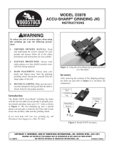
Figure 7. Tapping locations for a ring test.
/