Watts ISCA-121-D-BF Installation guide

Type
Installation guide
WARNING
!
Installation Instructions
Industry Standard Water
Closet Carriers
500 lb. Carriers - ISCA-101/ISCA-121/ISCA-131/
ISCA-141/ISCA-151
750 lb. Carriers - ISCA-103/ISCA-123/ISCA-133
1000 lb. Carriers - ISCA-102/ISCA-122/ISCA-132
Carriers for Floor Mounted Back Outlet Bowls (suf-
fix -BF)
WARNING
!
Local building or plumbing codes may require
modifications to the information provided. You
are required to consult the local building and
plumbing codes prior to installation. If the
information provided here is not consistent
with local building or plumbing codes, the
local codes should be followed. This product
must be installed by a licensed contractor in
accordance with local codes and ordinances.
Read Manual BEFORE using this equipment.
Failure to read and follow all safety and use information can result in death,
serious personal injury, property damage, or damage to the equipment.
Keep this Manual for future reference.
NOTICE
Follow the guidelines listed here for
proper installation, operation, and main-
tenance.
2
Packaging
Industry Standard Water Closet Carriers typically ship in two components. The
carrier faceplate assembly anchors to the floor and supports the bowl. The carrier
fitting attaches to the rear of the faceplate assembly, and connects to the sanitary
piping system.
All Watts faceplates are shipped pre-assembled. 500 lb., 750 lb., and Floor Mounted
Back Outlet faceplates ship boxed. 1000 lb. IS-FP-1-1000 faceplates and carrier
fittings ship loose.
Mounting StudCap Nut
Nipple
Upright
Fitting Gasket
500 lb. Carrier Installation
1.) Locate the rough-in dimension for the fixture outlet centerline from the floor on
the bowl manufacturer’s rough-in sheet. Uprights are scored with incremental height
markings to reference the nipple centerline. Adjust the uprights to match the carrier
nipple centerline to the bowl outlet centerline by loosening the side hex bolts. Note
for low rough-ins, the rounded bottom of the faceplate may need to be removed
along the scored lines.
2.) Attach each carrier upright to a concrete floor with a minimum of one 1/2" dia.
anchor bolt. (supplied by others).
3.) Position the oval fitting gasket between the faceplate and the fitting, with the
gasket lip facing back towards the fitting. Making sure the oval gasket is properly
seated, loosely attach the faceplate assembly to the carrier fitting through the gasket
ears with four 1/2" flanged hex bolts and washers (supplied).
Note: When the carrier fitting is set in a high position the flanged fitting bolts
may conflict with the compression seal boss. If this occurs, replace the two
lower flanged fitting bolts with 1/2" Allen Head bolts and clipped washers
(supplied).
Faceplate
Assembly
Carrier
Fitting
3
Battery Pitch & Rough-In Requirements
C/Bowl Outlet
from Floor
Min. C/L Horiz.
Waste from Floor
Max. C/L Horiz.
Waste from Floor
4 1/2"(115) 3"(76) 4 1/2”(115)
5"(127) 3"(76) 5”(127)
5 1/2"(140) 3”(76) 5 1/2”(140)
6"(152) 3”(76) 6”(152)
6 1/2"(165) 3 1/4"(82) 6 1/2”(165)
7"(178) 3 5/8"(92) 7”(178)
7 1/2"(191) 4 1/8"(105) 7 1/2”(191)
8"(203) 4 5/8"(118) 8”(203)
8 1/2"(216) 5"(127) 8 1/2”(216)
9"(229) 5 3/8"(137) 9”(229)
9 3/8"(239) 5 3/4"(146) 9 3/8”(239)
5.) Once the faceplate and fitting heights are set, ensure the four upright bolts and
four fitting bolts are securely tightened.
6.) Secure the rear anchor support rod through the boss on the back of the carrier
fitting with two hex nuts and washers (supplied) and adjust the height. Attach the
anchor foot to a concrete floor using a 1/2" dia. anchor bolt (supplied by others).
Pipe Chase
Rear Anchor
Support
4.) Adjust the carrier fitting to the desired height before tightening the fitting to the
faceplate. Reference Battery Pitch and Rough-in Requirements to determine the
minimum and maximum fitting centerline heights to configure horizontal carrier
batteries.
4
Finished
Wall
Faceplate
Assembly
Carrier
Fitting
Back-Up Nut
& Washer
Bowl
Gasket
ABS
Nipple
Compression
Flange & Gasket
Oval Fitting
Gasket
Bowl Gasket
7.) Install the ABS nipple inside the compression seal. Do not apply sealant or
lubricant to the compression gasket. Position the nipple so the front horn extends
5/16"(8) beyond the finished wall. If necessary the nipple can be shortened by cutting
from the backside (plain end). A styrofoam sleeve is provided to maintain an open
area around the nipple for compression bolt access.
Note: For wide chase installations the carrier nipple may be extended up to
4"(102) (option M1). If a longer nipple is not available, Sch. 40 PVC or ABS
pipe may be substituted. Beyond 4"(102) an auxiliary support (option CA-
100-EXT) is required to support the nipple and rods at the finished wall.
Extended 5/8"(16) all thread rods are furnished by the installing contractor.
8.) Tighten the four compression seal bolts to a torque of 30-50 in. lbs. to secure the
nipple. If a torque wrench is not available, the bolts can be tightened with a standard
socket or open end wrench.
Note: The compression seal will engage and positively seal the nipple with a
minimum amount of force. Do not overtighten the compression bolts.
9.) Adjust the carrier mounting studs to extend approx. 2 1/4”(57) beyond the
finished wall. Adjust the back-up nuts flush with the finished wall, with the back-up
washers outside the wall. When properly positioned, the back-up washers create a
1/16”(2) gap between the back of the bowl and the face of the finished wall.
10.) Following the system pressure test and prior to setting the bowl, knock out the
nipple test cap with a hammer. Make sure any sharp edges or burrs inside the nipple
resulting from the knockout are removed so the waterway is unobstructed.
11.) Remove the adhesive backing from both sides of the bowl gasket. Adhere the
gasket to the back of the bowl, centered around the bowl outlet. Install the bowl onto
the carrier, making sure the bowl gasket is properly seated against the nipple.
Note: Prior to setting the bowl, double check the depth of the nipple to
confirm it extends 5/16”(8) outside the finished wall. The nipple must be
properly positioned for the bowl gasket to create a positive seal.
12.) Install the four chrome cap nuts and plastic washers to secure the bowl.
Note: It is common industry practice for three cap nuts to be fully tightened,
and the fourth left hand tight. This reduces potential stress that can cause the
bowl to crack under heavy loading.
750 lb. & 1000 lb. Carrier Installation
Note: Follow the installation sequence for 500 lb. carriers, with the exceptions below.
1.) 750 lb. and 1000 lb. carriers are supplied with a rear anchor bar that must be
secured with two 1/2" dia. anchor bolts (supplied by others).
2.) The nipple and rods for 750 lb. and 1000 lb. carriers cannot be extended beyond
the maximum dimension of the factory supplied assembly.
Carriers for Floor Mounted Back Outlet Bowls (suffix -BF)
Note: Carriers for floor mounted back outlet bowls are used to transition from
the bowl outlet to the sanitary piping system, and to form carrier batteries.
Follow the installation sequence for 500 lb. carriers, with the exceptions
below.
1.) -BF faceplate assemblies are supplied with a special plate to accommodate a
4”(102) rough-in for back outlet bowls. The bowl is secured to the carrier with two
attachment studs and chrome plated acorn nuts (provided).
2.) A rear anchor support is not required for -BF carriers.
5
Limited Warranty: Watts Regulator CO. (the “Company”) warrants each product to be free from defects in material and
workmanship under normal usage for a period of one year from the date of original shipment. In the event of such defects
within the warranty period, the Company will, at its option, replace or recondition the product without charge.
THE WARRANTY SET FORTH HEREIN IS GIVEN EXPRESSLY AND IS THE ONLY WARRANTY GIVEN BY THE COMPANY
WITH RESPECT TO THE PRODUCT. THE COMPANY MAKES NO OTHER WARRANTIES, EXPRESS OR IMPLIED. THE
COMPANY HEREBY SPECIFICALLY DISCLAIMS ALL OTHER WARRANTIES, EXPRESS OR IMPLIED, INCLUDING BUT NOT
LIMITED TO THE IMPLIED WARRANTIES OF MERCHANTABILITY AND FITNESS FOR A PARTICULAR PURPOSE.
The remedy described in the first paragraph of this warranty shall constitute the sole and exclusive remedy for breach
of warranty, and the Company shall not be responsible for any incidental, special or consequential damages, including
without limitation, lost profits or the cost of repairing or replacing other property which is damaged if this product does not
work properly, other costs resulting from labor charges, delays, vandalism, negligence, fouling caused by foreign material,
damage from adverse water conditions, chemical, or any other circumstances over which the Company has no control.
This warranty shall be invalidated by any abuse, misuse, misapplication, improper installation or improper maintenance or
alteration of the product.
Some States do not allow limitations on how long an implied warranty lasts, and some States do not allow the exclusion
or limitation of incidental or consequential damages. Therefore the above limitations may not apply to you. This Limited
Warranty gives you specific legal rights, and you may have other rights that vary from State to State. You should consult
applicable state laws to determine your rights. SO FAR AS IS CONSISTENT WITH APPLICABLE STATE LAW, ANY IMPLIED
WARRANTIES THAT MAY NOT BE DISCLAIMED, INCLUDING THE IMPLIED WARRANTIES OF MERCHANTABILITY AND
FITNESS FOR A PARTICULAR PURPOSE, ARE LIMITED IN DURATION TO ONE YEAR FROM THE DATE OF ORIGINAL
SHIPMENT.
IS-WD-CA-Installation 2031 EDP# 8186409 © 2020 Watts
USA: T: (800) 338-2581 • F: (828) 248-3929 • Watts.com
Canada: T: (888) 208-8927 • F: (888) 479-2887 • Watts.ca
Latin America: T: (52) 55-4122-0138 • Watts.com
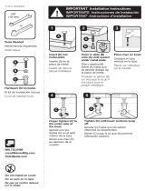
Need for Periodic Inspection/Maintenance: This product
must be tested periodically in compliance with local codes,
but at least once per year or more as service conditions
warrant. All products must be retested once maintenance
has been performed. Corrosive water conditions and/or
unauthorized adjustments or repair could render the product
ineffective for the service intended. Regular checking and
cleaning of the product’s internal and external components
helps assure maximum life and proper product function.
WARNING
!
NOTICE
Inquire with governing authorities for local installation
requirements
  • Page 1 1
  • Page 2 2
  • Page 3 3
  • Page 4 4
  • Page 5 5
  • Page 6 6
  • Page 7 7
  • Page 8 8
  • Page 9 9
  • Page 10 10
  • Page 11 11
  • Page 12 12
  • Page 13 13
  • Page 14 14
  • Page 15 15
  • Page 16 16
  • Page 17 17
  • Page 18 18

Watts ISCA-121-D-BF Installation guide

Type
Installation guide

Ask a question and I''ll find the answer in the document

Finding information in a document is now easier with AI