Page is loading ...

SERVICE
MANUAL
E35 CONVECTION OVEN
Revision 5/F3512
January, 2004
Manual P/N M0ME35

-3-
Revision 5/F3512
CONTENTS
This manual is designed to take a more in depth look at the E35 convection oven for the purpose of making
the unit more understandable to service people.
There are settings explained in this manual that should never require to be adjusted, but for completeness
and those special cases where these settings are required to change, this manual gives a full explanation
as to how, and what effects will result.
SECTION PAGE NO.
1. SPECIFICATIONS.............................................................................................................................. 5
2. INSTALLATION.................................................................................................................................. 8
3. OPERATION....................................................................................................................................... 10
3.1 Description of Controls
3.2 Explanation of Control System
4. MAINTENANCE ................................................................................................................................. 15
4.1 Cleaning
4.2 Routine Procedures
5. TROUBLE SHOOTING GUIDE .......................................................................................................... 17
6. SERVICE PROCEDURES.................................................................................................................. 20
6.2 Access
6.3 Replacement
6.4 Adjustment / Calibration
7. ELECTRICAL SCHEMATICS ............................................................................................................ 36
8. ELECTRICAL WIRING DIAGRAMS .................................................................................................. 39
9. SPARE PARTS .................................................................................................................................. 42
10. ACCESSORIES / OPTIONS............................................................................................................... 45
IMPORTANT: MAKING ALTERATIONS MAY VOID WARRANTIES AND APPROVALS.

-4-
Revision 5/F3512
PARTS DIAGRAMS ..................................................................................................................................... 46
11.1 Main Assembly
11.2 Control Panel Assembly
11.3 Gear Plate Assembly
11.4 Door Assembly
SERVICE CONTACTS ................................................................................................................................. 60
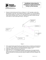
APPENDIX A. STACKING KIT INSTRUCTIONS........................................................................................ 62
APPENDIX B. STAND MOUNTING INSTRUCTIONS ................................................................................ 65
APPENDIX C. MOTOR CONTROL AND STEAM TIMER ADJUSTMENT GUIDE .................................... 66

-5-
Revision 5/F3512
VENT Ø 76 O.D.
MWS
40
E
3
630
9
MWS
720
880
78
3
E
800
0
165
6650
880
165
WATER ENTRY
3
E
MWS
ELECTRICAL ENTRY
1. SPECIFICATIONS
MODEL: E35-26
LEGEND
- Electrical connection entry point
- Water entry - 3/4” BSP hose connection
PLAN
Dimensions shown in millimetres.
Dimensions in inches shown in brackets.
SIDE
FRONT
880
(34.6)
78
(3.0)
720
(28.3)
665
(26.2)
165
(6.5)
880
(34.6)
48
(1.9)
800
(34.6)
155
(6.1)
55
(2.2)
12
(0.5)
40
(1.6)
(3.0)
630
(24.8)

-6-
Revision 5/F3512
3
E
880
78
MWS
E
3
630
41
MWS
VENT Ø 76 O.D.
WATER ENTRY
ELECTRICAL ENTRY
155
800
E
3
0
7650
980
165
MWS
12
MODEL: E35-30
LEGEND
- Electrical connection entry point
- Water entry - 3/4” BSP hose connection
PLAN
Dimensions shown in millimetres.
Dimensions in inches shown in brackets.
FRONT
SIDE
880
(34.6)
78
(3.0)
720
(28.3)
765
(30.1)
165
(6.5)
980
(38.6)
48
(1.9)
800
(34.6)
155
(6.1)
55
(2.2)
12
(0.5)
40
(1.6)
(3.0)
630
(24.8)

-7-
Revision 5/F3512
LOCATION
To ensure correct ventilation for the motor and
controls the following minimum installation
clearances are to be adhered to:
Rear 0mm / 0“
Left-hand side 0mm / 0”
Right-hand side 75mm / 3.0”
OVEN INTERNAL DIMENSIONS
E35-26
Width 465mm / 18
1
/
4
”
Height 685mm / 27”
Depth 760mm / 30”
Oven Volume 0.24m³ / 8.5ft³
E35-30
Width 465mm / 18
1
/
4
”
Height 685mm / 27”
Depth 860mm / 34”
Oven Volume 0.27m³ / 9.7ft³
OVEN RACK SIZE
Width 460mm / 18” or 405mm / 16”
(Adjustable shelf width)
Depth 660mm / 26” or 760mm / 30”
(Based on oven size model)
OVEN RACK SPACING
6 Tray (standard) 105 mm / 4
1
/
8
”
8 Tray (option) 78 mm / 3“
ELECTRICAL SUPPLY SPECIFICATION
OPTIONS
208V, 60Hz, 1P+N+E, 53.7A, 11.2 kW
220V, 50Hz, 1P+N+E, 56.8A, 12.5 kW
220-240V, 60Hz, 1P+N+E, 52.0A, 12.5 kW
230-240V, 50Hz, 1P+N+E, 52.0A, 12.5 kW
208V, 60Hz, 3P+E, 31A/Ph, 11.2 kW
220V, 50Hz, 3P+E, 33A/Ph, 12.5 kW
220-240V, 60Hz, 3P+E, 50.7A/Ph, 12.5 kW
220V, 60Hz, 3P+E, 32.8A/Ph, 12.5kW
380V, 60Hz, 3P+N+E, 18.9A/Ph, 12.5kW
380V, 50Hz, 3P+N+E, 18.9A/Ph, 12.5 kW
400-415V, 50Hz, 3P+N+E, 17.4A/Ph, 12.5 kW
400-415V, 50Hz, 3P+N+E, 11A/Ph, 8kW
ELECTRICAL CONNECTION WIRE
CONDUCTOR SIZES
1P+N+E/Gnd 6AWG/10mm² Copper T75 min
3P+E/Gnd 10AWG/6mm² Copper T75 min
3P+N+E/Gnd 12AWG/4mm² Copper T75 min
WATER SUPPLY CONNECTION
Max Pressure 550 kPa / 5.5 bar / 80 psi
Min Pressure 100 kPa / 1.0 bar / 15 psi

-8-
Revision 5/F3512
It is most important that the oven is installed
correctly and that the operation is correct
before use. Installation shall comply with local
electrical, health and safety requirements.
BEFORE CONNECTION TO POWER SUPPLY
Unpack and check unit for damage and report
any damage to the carrier and dealer. Report
any deficiencies to your dealer. Fit the feet which
are packed inside the oven. Check that the avail-
able power supply is correct to that shown on the
rating plate located on the right-hand side panel.
208V, 60Hz, 1P+N+E, 53.7A, 11.2 kW
220V, 50Hz, 1P+N+E, 56.8A, 12.5 kW
220-240V, 60Hz, 1P+N+E, 52.0A, 12.5 kW
230-240V, 50Hz, 1P+N+E, 52.0A, 12.5 kW
208V, 60Hz, 3P+E, 31A/Ph, 11.2 kW
220V, 50Hz, 3P+E, 33A/Ph, 12.5 kW
220-240V, 60Hz, 3P+E, 50.7A/Ph, 12.5 kW
220V, 60HZ, 3P+E, 32.8A/Ph, 12.5kW
380V, 60Hz, 3P+N+E, 18.9A/Ph, 12.5kW
380V, 50Hz, 3P+N+E, 18.9A/Ph, 12.5 kW
400-415V, 50Hz, 3P+N+E, 17.4A/Ph, 12.5 kW
400-415V, 50Hz, 3P+N+E, 11A/Ph, 8kW
LOCATION
To ensure correct ventilation for the motor and
controls the following minimum installation clear-
ances are to be adhered to:
Rear 0mm / 0“
Left-hand side 0mm / 0”
Right-hand side 75mm / 3.0”
Position the oven in its allocated working posi-
tion. Use a spirit level to ensure the oven is level
from side to side and front to back. (If this is not
carried out, uneven cooking could occur). The
feet/legs used with bench or floor mounting or
provided with stands are adjustable and will re-
quire adjusting in levelling the unit. It should be
positioned so the operating panel and oven
shelves are easily reachable for loading and
unloading.
2. INSTALLATION
WARNING: THIS APPLIANCE MUST BE GROUNDED.
WARNING: ALL INSTALLATION AND SERVICE REPAIR WORK MUST BE CARRIED OUT BY
QUALIFIED PERSONS ONLY.
Bench Mounting
For bench mounted applications the oven must
be fitted with 100mm / 4inch feet.
Floor Mounting
For floor mounted applications the oven must be
fitted with 150mm / 6 inch legs.
Note:
Four 100mm/4 inch or 150mm/6 inch ad-
justable legs are available separately from your
E35 dealer as an optional extra.
Stand Mounting
Ovens that are to be mounted on stands do not
require feet or legs. Refer to Appendix B for
stand mounting instructions.
Avoid having heat producing equipment such as
fryers or steamers adjacent to the right-hand side
of oven.
BEFORE USE
Operate the oven for about 1 hour at 200°C
(400°F) to remove any fumes or odours which
may be present.
ELECTRICAL CONNECTION
Remove side cover panel to allow access to the
terminal block and strain relief cable clamp. The
cable can be fitted through the entry grommet
and secured from strain by tightening the fitted
strain relief bushing. Connect cable to the
terminals as marked. Refit cover panel.
IMPORTANT: FIXED WIRING
INSTALLATIONS MUST INCLUDE AN
ALL-POLE DISCONNECTION SWITCH.
Refer to specifications section for wire
connections required, and supply connection
conductor sizes.
IMPORTANT: THE OVEN VENT
LOCATED ON THE CABINET TOP MUST
NEVER BE OBSTRUCTED.

-9-
Revision 5/F3512
IMPORTANT: MAXIMUM INLET WATER
PRESSURE IS 550 kPa / 80 psi.
WATER CONNECTION
A cold water supply should be fitted to the water
inlet (
3
/
4
” BSP hose connection) which is located
on the rear of the right hand side of the unit.
Alternately, a connection elbow and sealing
washer is supplied with this unit for direct
connection of a
1
/
2
” ID hose, which is
recommended for easy installation and service.
Connect water supply - Max inlet pressure 80psi /
550kPa.
Turn on water supply to check for leaks.
DOUBLE STACKING UNITS
When it is desired to mount an E35 Turbofan
oven on an E85 prover, a double stacking kit
must be used. Available from your dealer or Tur-
bofan distributor. (see Spare Parts).
When mounting one oven on top of another, a
double stacking kit is also required.
For stacking kit assembly instructions, refer to
Appendix A.
RACK WIDTH POSITIONS
The E35 models have an adjustable rack width
setting. This allows for the racking to be
configured for 405mm/16” or 460mm/18” wide
baking sheets/pans or racks.
Position the side racks in their innermost position
for 16” trays and in their outermost position for
18” trays.
Removal of Side Racks (as illustrated)
1) Lift the side rack off the bottom locating pins.
2) Move bottom of rack toward centre of oven.
3) Lower rack to clear top locating pins, and
remove.
Replacement of Side Racks
1) Insert rack into the oven, placing the
appropriate holes over the top locating pins.
2) Lift the side rack over the bottom locating
pins.
3) Lower rack with appropriate holes over bot-
tom locating pins.
RATING PLATE LOCATION
The rating plate for the E35 convection oven is
located at the bottom left corner of the RH side
panel. An internal rating plate is also located
behind the RH side panel on the vertical dividing
panel behind the electrical contactors. (Units
manufactured from July 2002).
Figure 2.2
Locating Stud
Figure 2.3
Rating Plate
Internal Rating Plate

-10-
Revision 5/F3512
3.1 DESCRIPTION OF CONTROLS
3. OPERATION
NOTE: A full user’s operation manual is supplied with the product and can be used for further referencing
of installation, operation and service.
1. VENT
Oven vent closed (incorporates over-
pressure relief when closed).
Oven vent open (light illuminates).
2. THERMOSTAT
Temperature range 60 - 280°C / 100 - 550°F.
(Light illuminates when elements are cycling ON
to maintain set temperature).
3. TIMER
1 Hour bake timer.
(Light illuminates when “time up” (0) reached, and
buzzer sounds).
4. STEAM BUTTON
Push button to activate automatic steam dose
into oven chamber.
(Light illuminates when button activated for
duration of steam cycle).
5. FAN SPEED
HI Full fan speed (Star point connection on
motor).
LO Half fan speed (Delta point connection
on motor).
6. POWER
O UNIT IS OFF
I UNIT IS ON (Light illuminates when
switched to this position).
Oven lights operate continuously.
Fan starts after 10 seconds when door
closed.
1
2
3
4
5
6

-11-
Revision 5/F3512
Oven Lamps
The two oven lamps (12 volt halogen) are on
whenever the Power switch is on. The oven
lamps are supplied with 12 volts from an
electronic lamp transformer fitted on the
oven’s control switchgear assembly. The oven
lamps are on with the oven door open and
closed.
Bake Timer
The 60 minute bake timer is a mechanical timer
and can therefore be operated with the oven’s
power ON or OFF. However only with the oven’s
power switch On and the oven door closed will
the timer turn on the time-up buzzer and time-up
indicator neon on the control panel. The buzzer
and time-up indicator provide indication that the
time setting has run down to zero and at this point
will remain on continuously until the 60 minute
timer has been manually set back to the Off
(vertical) position. The 60 minute timer does not
control any other part of the oven’s operating
system as the timer is independent of the
temperature control, heating, fan, or steam
system.
Oven Vent
The oven vent is a manual operation by way of
the Vent knob on the control panel.
The vent knob directly rotates the vent shaft
through 90 degrees to open and close the vent.
The vent shaft passes through a rotary switch
mounted behind the control panel and this switch
is used to switch on or off the Vent indicating
neon. In the vent open position the indicator is
illuminated. The oven vent restricts venting of the
oven when in the closed position, however the
vent flap is fitted with a spring loaded
over-pressure flap which relieves excess
pressure created during oven steaming. This
avoids steam pressure escaping out of door seals
etc, if the oven is steamed with the vent closed.
The spring pressure on the over-pressure vent
flap ensures that only excess steam is lost out of
the vent.
Door Switch
The oven has a door switch, mechanical
micro-switch below oven opening, which breaks
the power supply to the oven fan, temperature,
and steam control circuits when the door is
opened. Additionally, opening the oven door will
remove power from the Bake Timer buzzer and
indicator, and the vent position indicator neon.
3.2 EXPLANATION OF CONTROL
SYSTEM
The E35 Turbofan convection oven features
multi-function operator controls, and a combined
fan motor and steam control system.
A correct understanding of their operation is
required before carrying out any service or fault
repair work. The control device functions are
explained as follows:
Circuit Protection
All models are fitted with a 3 pole circuit breaker,
from which a control circuit is taken from L1
circuit breaker, and this control circuit is fitted with
a 6A circuit breaker. The 3 pole main circuit
breakers are rated 25A/pole for 3P+N+E/GND
and 1P+N+E/GND supply models, and 40A/pole
for 3P+E/GND (no neutral) models. These pro-
vide control circuit protection via the 6A circuit
breaker, and load circuit protection via the 3 pole
circuit breakers.
Additionally, the 3 pole circuit breaker is
mechanically connected to a Shunt Trip breaker,
which in the event of the oven fan motor
overheating will trip the 3 pole circuit breakers to
isolate power from the unit. The Shunt Trip is
directly connected to thermal limit switches in the
motor windings, and the supply Neutral (or L3 on
3 phase, no neutral models). A supply from the
6A control circuit breaker is connected to the
motor thermal switches. Should any of the motor
windings overheat, the thermal switches close
and supply power to the Shunt Trip, which in turn
trips (triggers) and mechanically trips the 3 pole
circuit breaker.
Accordingly, causes of circuit breakers tripping
can be ascertained with the above knowledge,
and this is covered in more detail in the Fault
Diagnosis section.
Power On/Off
A Power switch on the control panel isolates
power to the operator controls of the oven. With
the power switch OFF all functions of the oven
are inoperable.
An integral cooling fan, behind the control panel
used to keep the electrical controls of the oven
cool, is on continuously whenever the power
supply to the oven is on. Switching the oven
control panel Power switch off will leave the
cooling fan running.
With the Power switch ON (illuminated neon
indicator), power is supplied to all operator
controls.

-12-
Revision 5/F3512
This allows only the oven lights to be operational
if the oven door is opened.
Thermostat Control
Heating of the oven is controlled by an
electronic thermostat control, comprising of a
potentiometer dial and knob on the control panel,
a temperature sensing probe (thermistor type) in
the oven chamber, and the thermostat control
board behind the control panel. Power to the
electronic thermostat is supplied through an
over-temperature/hi limit thermostat. Accordingly
a failure of the electronic thermostat control
causing a temperature over-run will result in the
over-temperature thermostat switching and
removing power from the heating control circuit.
The over-temperature thermostat is able to be
manually reset, however a serviceman is required
to perform this function, as removal of the R/H
service panel is required to access this safety
protection device.
The electronic thermostat when set to a
temperature will illuminate the heating neon
indicator on the control panel whenever the oven
heating elements are on. When the indicator
neon goes out, the oven is up to the set
temperature.
Heating / Elements
The electronic thermostat when requiring heating
of the oven, switches power to the heating
contactor (referred to as C1 contactor in this
manual). The heating contactor closes to supply
power through to the heating elements in the
oven. In all ovens all 3 poles of the contactor are
used to supply L1, L2, and L3 phase circuits to
the 3 heating elements on each side of the oven
fan motor.
On 3 Phase + Neutral supply models, all 6
elements are looped to neutral, and the 3 Phase
power to the elements is to each set of three
elements in parallel connection. Hence each of
the elements is supplied with the Phase to
Neutral voltage.
On 3 Phase supply models (no neutral), the set
of three elements each of the fan motor are
connected in Delta configuration, which each
element being supplied the Phase to Phase
voltage.
On 1 Phase + Neutral supply models, all 6
elements are looped to neutral, and the 1 Phase
power to the elements is split into three poles at
the main circuit breakers on the oven, then feed
through the three poles of the heating contactor,
from where each pole is connected to two of the
six elements in parallel. Hence each of the
elements is supplied with the Phase to Neutral
voltage.
The heating elements are rated at 2000 Watts
each, therefore providing a total of 12000 Watts
or 12kW of heating.
In some cases special heating kilowatts may be
supplied to special request, so always check
rating plate information on the unit if in doubt.
The heating contactor cycles ON/OFF as
controlled by the thermostat to maintain set oven
temperature.
Fan / Motor
The E35 Turbofan ovens use a dual speed,
bi-directional oven fan circulation system, in order
to provide even heat distribution through the
oven, and fan speed control to suit different
product types.
To provide both dual fan speed and bi-direction, a
motor of 4pole/8pole configuration is used.
Fan / Motor Direction
The direction change is made by swapping two
phases to the motor through the motor contactors
C2 and C3. In one direction L1, L2, and L3 are
switched through motor contactor C2 with motor
contactor C3 open. In the alternate direction,
motor contactor C2 is open, and C3 is closed. L1
and L2 are reversed on the C3 contactor
connections. Motor contactors C2 and C3 are
mechanically interlocked (interlock fitted to rear of
contactors) to prevent any switching overlap.
Motor direction change is automatic, and the
duration of the direction cycle is factory set.
Additionally, a dwell period between at each
change of direction occurs to allow the motor to
restart in the opposite direction only after the
motor rotation has slowed down. This is
necessary to avoid motor overheating due to the
high current load that would be required to
change direction instantaneously.
Each direction cycle is 90 seconds long, at the
beginning of which is a preset 10 second dwell/
delay. As the dwell is at the beginning of the cy-
cle, the fan always has a 10 second start delay
when the oven is first turned on, or when the door
is closed after opening.
The direction control timing is provided from three
electronic timers mounted below the motor
contactors on the electrical switchgear panel of
the oven. Timer T1 controls the direction cycle
time, timer T3 controls the dwell for one direction,
and timer T5 controls the dwell for the opposite
direction.

-13-
Revision 5/F3512
When the door is closed and power is ON, cycle
timer T1 will switch power to dwell timer T3 for 90
seconds. Timer T3 will then switch power
through to motor direction contactor C2 after the
preset 10 second delay. The motor will then run
for the remainder of the 90 second cycle.
At the completion of the 90 second cycle,
cycle timer T1 will switch the power from T3 dwell
timer to T5 dwell timer. This T3 dwell timer will
then switch power through to the other motor
direction contactor (refer previous) after the
preset 10 second delay, and the motor will run in
the opposite direction for the remainder of that 90
second cycle. At the completion of that cycle the
cycle timer T1 switches power back to the other
dwell timer, and this continues until the oven door
is opened, or the power is turned off.
Fan / Motor Speed
For HI speed operation the motor is run as a 4
pole motor. (1420 rpm 50Hz/1750 rpm/60Hz) For
LO speed operation the motor is run as an 8 pole
motor. (715 rpm 50Hz/850 rpm/60Hz)
Selection of the pole configuration for run speed
is made though the motor contactors C4, C5 and
C6.
In HI speed setting the motor contactors C4 and
C6 close, C4 switching power to the motor on the
4 pole connection leads, and C6 binding 4 of the
8 motor poles to allow motor to run as a 4 pole
motor.
In LO speed setting the motor contactor C5
closes to switch power to the motor on the 8 pole
connections leads, with contactors C4 and C6
remaining open.
Motor contactors C5 and C6 are mechanically
interlocked (interlock fitted to rear of contactors)
to prevent any switching overlap between LO and
HI speed changes.
The motor speed control is by manual operation
of the Fan Speed switch on the control panel.
This rotary switch simply supplies power to either
motor contactors C4 and C6 for HI speed, or C5
for LO speed. The contactors stay closed in the
selected setting unless the oven door is opened.
Closing the oven door allows the contactors to
switch on again.
Fan / Motor - Single Phase Models
The operation of the fan motor on single phase
E35 models is the same as other three phase
models for two speed and bi-direction operation,
except for the electrical circuit required.
On single phase models the same motor is used
as on three phase models, but with capacitors in
the motor circuit to create an artificial phase lag,
that is normally part of the three phase supply on
three phase models. Use of the three phase
motor is required to retain the bi-direction
operation.
On single phase models the L1 supply to the
motor connects to the normal L1 connection of
the motor, and the Neutral supply connects to the
normal L2 (as connected on three phase models)
connection of the motor. A capacitor is then
connected to the normal L3 (as connected on the
three phase models) connection of the motor, and
this capacitor is supplied power from the L1/
Phase supply. This capacitor is referred to as the
Run capacitor as it is permanently in the circuit
during motor operation. Each motor on single
phase models has two run capacitors, one for the
LO speed operation (lower capacitance) and one
for the HI speed operation (higher capacitance).
Each Run capacitor is only used when the motor
is running at that speed setting.
Additionally a Start capacitor is also fitted on
single phase models, and is used for starting the
motor rotation at the beginning of each direction
change when in HI speed setting only. This
capacitor is switched on for approximately 7
seconds only at the beginning of each motor start
up, with a contactor C7 switching the Start
capacitor on and off, and with a timer T6
controlling the timing of the contactor C7.
Fan direction change in single phase models is
still controlled by motor contactors C2 and C3.
However unlike three phase models where C2
and C3 swap phases over to change motor start
rotation/direction, single phase models use C2
and C3 to switch the run capacitor form the L1
supply to the Neutral supply for direction change.
Control of the motor cycle timing and dwell timing
is the same as three phase models.
Motor Protection
Refer Circuit Protection at start of section.
Steam System
The E35 Turbofan ovens feature an
automatically timed oven chamber steaming
system, that allows operators to inject a 10
second period of steam into the oven at any
stage. The steam is generated when a solenoid
valve opens and supplies mains water to a
calibrated wide spray angle nozzle in the oven
that discharges the water as a fine spray into the
oven fan. The fine spray at a wide angle is then
immediately thrown by the fan circulation across
the oven heating elements either side of the fan.
The fine spray instantaneously turns to steam on

-14-
Revision 5/F3512
the hot elements, which is supported by the hot
air of the oven also turning the water droplets into
steam.
The steam is initiated by depressing the Steam
switch on the control panel. When depressed the
steam switch provides power one of two Steam
timers which are preset to 10 seconds steam
cycle duration. These Steam timers are T2 and
T4.
T2 is associated with fan dwell timer T3 and is
used when steam is required during the fan
direction cycle that uses the T3 dwell timer.
T4 is associated with fan dwell timer T5 and is
used when steam is required during the fan
direction cycle that uses the T5 dwell timer.
This ensures that steam can be used in either fan
direction cycle, and additionally allows the fan to
be turned on as soon as steam is activated, even
if the fan was in a direction change dwell.
Ensuring that the fan is running when steam is
required is necessary to atomise the water
droplets by the mechanical action of the fan, and
by the fan throwing the water across the
elements.
The Steam switch on the control panel only
needs to be depressed momentarily as the
duration of the steam injection is automatically
timed by the steam timers. The Steam switch will
illuminate for the duration of the steam injection to
provide a visual confirmation of the steaming
process. The light in the steam switch is
independent of the switch contacts and is
powered by the electrical circuit to the water
solenoid valve. Therefore the switch is
illuminated for as long as the water solenoid is
open: 10 seconds.
Summary of Components
The electrical switchgear (not user controls)
components are summarised as follows:
C1 Heating contactor
Switches elements ON/OFF
C2 Motor direction contactor
Phases switched in line
C3 Motor direction contactor
Phases L1 and L2 swapped on 3 phase
models
Run capacitor swapped from L1 to
Neutral on 1 phase models
C4 Motor speed contactor
HI speed
C5 Motor speed contactor
LO speed
C6 Motor speed contactor
HI speed (changes motor from 8 pole
to 4 pole)
T1 Fan cycle timer
Direction cycle
T2 Steam timer
For T3 dwell direction
T3 Fan dwell timer
Alternate direction (always initial
direction dwell)
T4 Steam timer
For T5 dwell direction
T5 Fan dwell timer
Alternate direction (always 2
nd
direction
dwell)
C7 Motor start capacitor contactor.
(Single phase models only)
T6 Motor start capacitor timer
(Single phase models only)
Motor contactor interlocks fitted to C2+C3
(mounted on rear on contactors)
Motor contactor interlocks fitted to C5+C6
(mounted on rear on contactors)
The following Troubleshooting Guide should be
used to identify any incorrect oven operation. On
correct identification of the operating fault the
Troubleshooting guide will make reference to the
corrective action required, or refer to the Fault
Diagnosis section and/or Service section to assist
in correction of the fault.

-15-
Revision 5/F3512
IMPORTANT: THIS UNIT IS NOT
WATER PROOF.
DO NOT USE A WATER JET SPRAY TO
CLEAN INTERIOR OR EXTERIOR OF THIS
UNIT.
WARNING: ALWAYS TURN THE
POWER SUPPLY OFF BEFORE
CLEANING.
EXTERIOR
Clean with a good quality stainless steel cleaning
compound. Harsh abrasive cleaners may dam-
age the surface.
INTERIOR
Ensure that the oven chamber is cool. Do not use
wire brushes, steel wool or other abrasive materi-
als. Clean the oven regularly with a good quality
oven cleaner. Take care not to damage the fan
or the tube at the right side of the oven which
controls the thermostat.
SIDE RACKS
To remove, follow instructions given in the
installation section.
OVEN DOOR (HINGED GLASS)
Outer surfaces: Clean with conventional glass
cleaners
Inner surfaces: To clean between the inner and
outer door glasses, firstly ensure the door is
locked shut. With a screwdriver, coin, or other
suitable device,
1
/
4
turn the outer glass locks to
release the outer glass and allow it to be hinged
open for cleaning access (refer to figure 4.1 for
correct procedure).
4. MAINTENANCE
4.1 CLEANING
WARNING: ALL INSTALLATION AND SERVICE REPAIR WORK MUST BE CARRIED OUT BY
QUALIFIED PERSONS ONLY.
TOP
LOCKED
BOTTOM
UN-LOCKED
UN-LOCKED
LOCKED
Figure 4.1
Figure 4.2
OVEN DOOR (HINGED GLASS)
Outer surfaces: Clean stainless steel with quality
stainless steel cleaner.
Inner surfaces: Clean stainless steel with
quality stainless steel cleaner.
Door glass: Clean with conventional glass
cleaners.
OVEN SEALS
To remove, pull out the seal starting at each
corner. The seal may be washed in the sink, but
take care not to cut or damage it. To replace, fit
the seal in at the corners first, then push in the
rest of the seal.
IMPORTANT: ALWAYS ENSURE
THAT THE OUTER GLASS IS HINGED
CLOSED AND LOCKED INTO
POSITION BEFORE OPENING DOOR.

-16-
Revision 5/F3512
4.2 ROUTINE PROCEDURES
PROCEDURE INTERVAL
DOOR SEALS Check for deterioration. 12 months
DOOR PIVOT BUSHES Check for wear. 12 months
DOOR CATCH Ensure that catch is adjusted such that the door closes
properly.
12 months
ELEMENT Check that element resistance is correct to it’s rating (refer
6.3.12).
12 months
WATER NOZZLE Check for lime build-up in water nozzle. 12 months

-17-
Revision 5/F3512
5. TROUBLE SHOOTING
FAULT POSSIBLE CAUSE REMEDY
THE OVEN DOES NOT
OPERATE / START
The mains isolating switch on the
wall, circuit breaker or fuses are
“off” at the power board.
The power switch on the oven is
off (‘0’).
Incorrect electrical supply.
Oven circuit breaker tripped.
Power switch on unit faulty.
Turn on.
Turn switch to ‘I’ position.
Ensure electrical supply correct.
Identify fault.
Reset circuit breaker.
Replace.
(Refer service section 6.3.1)
FAN DOESN’T OPERATE Door not closed.
(Fan only operates when the
door is closed).
Door microswitch out of
adjustment.
Door microswitch faulty.
Fan motor faulty.
Wiring.
Fan timers.
Close door.
Adjust.
(Refer service section 6.4.1)
Replace.
(Refer service section 6.3.3)
Replace.
(Refer service section 6.3.21)
Check and tighten any loose
wiring.
Replace.
(Refer service section 6.3.11)
STEAM LIGHT DOES NOT
ILLUMINATE
Blown bulb. Replace bulb.
NO STEAM
(continued next page)
Water not turned on.
Blocked filter in water solenoid.
Nozzle blocked.
Check valve blocked/corroded.
Turn water on at isolating valve.
Clean filter.
Remove, clean or replace.
(Refer service section 6.3.16)
Remove check valve.
(Refer service section 6.3.15)
WARNING: ALL INSTALLATION AND SERVICE REPAIR WORK MUST BE CARRIED OUT BY
QUALIFIED PERSONS ONLY.

-18-
Revision 5/F3512
FAULT POSSIBLE CAUSE REMEDY
NO STEAM
(continued)
Steam tube blocked.
Faulty solenoid coil.
Steam switch faulty.
Timer faulty.
Remove, clean or replace.
Replace.
(Refer service section 6.3.16)
Replace.
(Refer service section 6.3.14)
Adjust / Replace.
(Refer service section 6.3.11)
STEAMS ONLY SOMETIMES Steam timer faulty.
Replace.
(Refer service section 6.3.11)
NO HEAT Faulty contactor.
Thermostat faulty.
Replace.
(Refer service section 6.3.11)
Replace.
(Refer service section 6.3.8)
SLOW RECOVERY Faulty contactor.
Element(s) blown.
Replace.
(Refer service section 6.3.11)
Replace.
(Refer service section 6.3.12)
NO TEMPERATURE
CONTROL
Faulty door microswitch.
Faulty heating contactor.
Over-temperature control tripped.
Faulty thermostat controls.
Adjust or replace.
(Refer service section 6.3.3)
Replace.
(Refer service section 6.3.11)
Reset.
Replace.
(Refer service section 6.3.7)
OVER-TEMPERATURE
CONTROL TRIPS
Oven too hot, thermostat out of
calibration.
Over-temp out of calibration.
Replace.
(Refer service section 6.3.8)
Replace.
(Refer service section 6.3.13)
TIMER WILL NOT TIME DOWN Faulty timer.
Replace.
(Refer service section 6.3.18)
NO TIME UP ALARM
INDICATION
Faulty timer.
Faulty buzzer.
Replace.
(Refer service section 6.3.18)
Replace.
(Refer service section 6.3.19)
NO HIGH FAN SPEED
NO LOW FAN SPEED
Fan selector switch faulty.
Fan selector switch faulty.
Replace.
(Refer service section 6.3.22)
Replace.
(Refer service section 6.3.22)

-19-
Revision 5/F3512
FAULT POSSIBLE CAUSE REMEDY
OVEN LIGHTS NOT
ILLUMINATING
Blown bulb(s).
Faulty lighting transformer.
NOTE: If both light bulbs have
blown then there will be no
output from the lighting
transformer.
Replace.
(Refer service section 6.3.4)
Replace.
(Refer service section 6.3.6)
OVEN VENT INDICATOR NOT
ILLUMINATING WHEN IN ‘OPEN’
POSITION
Indicator faulty.
Switch faulty.
Replace.
(Refer service section 6.3.2)
Replace.
(Refer service section 6.3.23)
OVER-PRESSURE VENT NOT
OPERATING DURING STEAM
CYCLE
Vent blocked.
Over-pressure vent mechanism
restricted.
Remove and clean blockage.
Remove and clean.
DOOR DOES NOT CLOSE Tray in way of door.
Door seal obstruction.
Door handle in wrong position.
Door setting incorrect.
Correctly position tray in rack.
Correctly install door seal.
(Refer maintenance section)
Reposition door handle.
Adjust.
(Refer service section 6.4.3)
DOOR SEAL LEAKS Door seal damaged.
Door seal incorrectly fitted.
Replace.
(Refer maintenance section)
Correctly install door seal.
(Refer maintenance section)
RACKS DO NOT FIT Incorrect pin location. Relocate on correct pin.

-20-
Revision 5/F3512
SECTION PAGE NO.
6.2 ACCESS ............................................................................................................................................. 22
6.2.1 Control Panel ...................................................................................................................... 22
6.2.2 Service Panel (RH Side Panel)........................................................................................... 22
6.2.3 Baffle................................................................................................................................... 22
6.2.4 Side Panel (LH Side) .......................................................................................................... 22
6.2.5 Control Panel Rear ............................................................................................................ 22
6.3 REPLACEMENT................................................................................................................................. 23
6.3.1 Power Switch ...................................................................................................................... 23
6.3.2 Indicator Neon Light............................................................................................................ 23
6.3.3 Door Microswitch ................................................................................................................ 23
6.3.4 Light Bulb / Glass................................................................................................................ 24
6.3.5 Light Fitting ......................................................................................................................... 24
6.3.6 Lighting Transformer........................................................................................................... 24
6.3.7 Thermostat Dial .................................................................................................................. 24
6.3.8 Thermostat Board ............................................................................................................... 25
6.3.9 Thermostat Probe ............................................................................................................... 25
6.3.10 Timer / Contactor ................................................................................................................ 26
6.3.11 Elements............................................................................................................................. 26
6.3.12 Over Temperature Thermostat ........................................................................................... 26
6.3.13 Steam Switch...................................................................................................................... 27
6.3.14 Spray Nozzle ...................................................................................................................... 27
6.3.15 Check Valve........................................................................................................................ 27
6.3.16 Water Solenoid ................................................................................................................... 27
6.3.17 Cooling Fan ........................................................................................................................ 28
6.3.18 Bake Timer ......................................................................................................................... 28
6.3.19 Buzzer................................................................................................................................. 28
6.3.20 Oven Fan ............................................................................................................................ 28
6.3.21 Fan Motor ........................................................................................................................... 29
6.3.22 Fan Speed Selector Switch ................................................................................................ 29
6.3.23 Vent Switch......................................................................................................................... 29
6.3.24 Vent / ‘Over Pressure’ Vent ................................................................................................ 29
6.3.25 Door Outer Glass................................................................................................................ 30
6.3.26 Door Inner Glass................................................................................................................. 30
6.3.27 Door Catches...................................................................................................................... 30
6.3.28 Door Handle........................................................................................................................ 30
6.3.29 Door Catch Mechanism ...................................................................................................... 30
6.3.30 Door Handle Mechanism .................................................................................................... 31
WARNING: ENSURE POWER SUPPLY IS SWITCHED OFF BEFORE SERVICING.
6. SERVICE PROCEDURES
WARNING: ALL INSTALLATION AND SERVICE REPAIR WORK MUST BE CARRIED OUT BY
QUALIFIED PERSONS ONLY.

-21-
Revision 5/F3512
6.4 ADJUSTMENT / CALIBRATION........................................................................................................ 31
6.4.1 Door Microswitch Adjustment ............................................................................................. 31
6.4.2 60 Minute Timer Zero Position Adjustment......................................................................... 31
6.4.3 Door Setting / Adjustment................................................................................................... 32
6.4.4 Door Reversal..................................................................................................................... 32
6.4.5 Fan and Steam Timer Operation / Adjustment ................................................................... 34
Fan / Steam Flow Chart...................................................................................................... 35
/