
This manual is the property of
Cembre:
any reproduction is forbidden without written permission.
Ce manuel est la proprieté de
Cembre:
toute reproduction est interdite sauf autorisation écrite.
Der Firma
Cembre
bleibt das Eigentumsrecht der Bedienungsanleitung vorbehalten.
Ohne vorherige schriftliche Genehmigung darf die Bedienungsanleitung weder vollständig noch teilweise vervielfältigt werden.
Este manual es propriedad de
Cembre.
Toda reproducción está prohibida sin autorización escrita.
Questo manuale è di proprietà della
Cembre:
ogni riproduzione é vietata se non autorizzata per scritto.
ENGLISH
FRANÇAIS
DEUTSCH
ESPAÑOL
ITALIANO
10 M 009
OPERATION AND MAINTENANCE MANUAL
NOTICE D'UTILISATION ET ENTRETIEN
BEDIENUNGSANLEITUNG
MANUAL DE USO Y MANTENIMIENTO
MANUALE D'USO E MANUTENZIONE
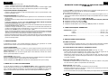
CRIMPING FORCE GAUGE
DISPOSITIF POUR VÉRIFIER LA FORCE DE SERTISSAGE
DRUCKMESSGERÄT
DISPOSITIVO VERIFICACIÓN FUERZA DE COMPRESIÓN
DISPOSITIVO PER LA VERIFICA DELLA FORZA DI COMPRESSIONE
cod. 6261324
MPC7
Cembre Ltd.
Dunton Park
Kingsbury Road, Curdworth - Sutton Coldfield
West Midlands B76 9EB (Great Britain)
Tel.: 01675 470440 - Fax: 01675 470220
E-mail: [email protected]
Cembre S.p.A.
Via Serenissima, 9
25135 Brescia (Italia)
Telefono: 030 36921
Telefax: 030 3365766
E-mail: [email protected]
Cembre S.a.r.l.
22 Avenue Ferdinand de Lesseps
91420 Morangis (France)
Tél.: 01 60 49 11 90 - Fax: 01 60 49 29 10
B.P. 37 - 91421 Morangis Cédex
E-mail: [email protected]
Cembre España S.L.
Calle Verano, 6 y 8 - P.I. Las Monjas
28850 Torrejón de Ardoz - Madrid (España)
Teléfono: 91 4852580
Telefax: 91 4852581
E-mail: [email protected]
Cembre AS
Fossnes Senter
N-3160 Stokke (Norway)
Phone: (47) 33361765
Telefax: (47) 33361766
E-mail: [email protected]
Cembre GmbH
Heidemannstraße 166
80939 München (Deutschland)
Telefon: 089/3580676
Telefax: 089/35806777
E-mail: [email protected]
Cembre Inc.
Raritan Center Business Park
181 Fieldcrest Avenue
Edison, New Jersey 08837 (USA)
Tel.: (732) 225-7415 - Fax: (732) 225-7414
E-mail: [email protected]
www.cembre.com
Page is loading ...

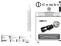
CRIMPING FORCE GAUGE
MPC7
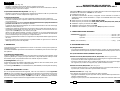
The MPC7 gauge has been designed to measure the maximum force developed by 15
to 60 kN
Cembre
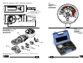
hydraulic tools and consists of (Ref. Fig. 1):
A Hydraulic force transducer, coupled to a dial gauge marked in coloured bands showing
acceptable levels of force for each type of tool.
B Test die-set for tools type
HT45, B35-45, B46 (all versions)
C Test die-set for tools type HT51, HT61, B35-50, B51, B55, B62, RH50, RH61 (all versions)
D Test adaptor for tools type B54 (all versions)
E AU55-50 adaptor for tools type B55 (all versions)
F AD-B15/MPC7 adaptor for tools type B15 (all versions), optional accessory.
1. GENERAL CHARACTERISTICS
– Dimensions: length ....................................................................... 472 mm (18.6 in.)
width ........................................................................ 260 mm (10.2 in.)
height ....................................................................... 225 mm (8.8 in.)
– Weight: (transducer) ..................................................................... 3,1 kg (6.8 lbs)
2. INSTRUCTIONS FOR USE
2.1) Setting
– With the hydraulic tool in the rest condition, that is, with the oil pressure completely
released and consequently with the ram fully retracted, continue as follows:
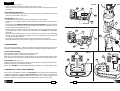
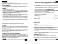
2.1.1) Inserting the adaptor/test die-sets
Tool type HT45; B35-45; B46; B35-50; B51; RH50 (Ref. Figs. 2a, 2b):
– Open the latch (01) and release the upper die holder (02).
– Insert the test dies (B or C) into the lower (03) and upper (02) die supports until the dies
lock.
Tool type HT61; B62; RH61 (Ref. Fig. 2c):
– Insert one test die (C) on the ram (04) then insert the other die into the
the upper part
of the head (05)
.
Tool type B54 (Ref. Fig. 2d):
With the tool free of it’s jaws, proceed as follow:
– Place the test adaptor (D) in the seat (S) of the transducer and insert it into the tool
(06).
– Fully insert the locking pin (07) into the hole of the adaptor (D) and lock it.
ENGLISH
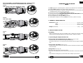
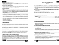
DEVICE POSITIONING - POSITIONNEMENT DU DISPOSITIF - ARBEITSPOSITION
COLOCACIÓN DEL DISPOSITIVO - POSIZIONAMENTO DEL DISPOSITIVO
FIG. 3b
HT61 ; B62 ; RH61
FIG. 3d
B55
FIG. 3a
HT45 ; B35-45 ; B46 ; HT51 ; B35-50 ; B51 ; RH50
13 2
FIG. 3c
B54

3
2
1
3
1
2
1
2
1
1
2
2
ENGLISH
01
FIG. 2a
02
02
03
03
04
05
312
Tool type B55 (Ref. Fig. 2e):
– Insert the AU55-50 adaptor (E) into the seat of the ram (08).
–
Insert one test die (C) into the adaptor AU55-50 (E) and one into the upper part of the
head (09).
2.2) Positioning the device
– Ensure that the hydraulic transducer is correctly located in the hydraulic tool head for
the tool type as shown in Figs. 3a-d.
2.3) Operation (Ref. Fig. 4)
– Position the tool so that it is easy both to operate and to read the dial.
– Actuate the tool so that the test dies exert a gradually increasing pressure on the trans-
ducer.
– Continue pumping until the maximum pressure valve is activated and a “click” is heard.
The pointer of the transducer will remain locked in the maximum compression force
position reached by the tool (Ref. Fig. 4).
– Check to make sure that the pointer is within the green band corresponding to the type
of tool being tested; if this is not the case, return the tool to
Cembre
for recalibration
(See § 4).
NOTE: RH50 and RH61 heads must be connected to a hydraulic pump developing
700 bar; in case of unsatisfactory reading, the pressure delivered by the pump should
be checked with MPC1 device.
– Completely re-open the dies using the pressure release device on the tool.
– Return the pointer to the start position using the pressure release lever on the device.
3. MAINTENANCE
The crimping force gauge is robust and requires very little daily maintenance however
compliance with the following points should help to maintain its optimum performance.
3.1) Accurate cleaning
Dust, sand and dirt are a danger for any hydraulic device.
Avoid putting the device on muddy or dusty ground.
After every use the crimping force gauge and test die-sets should be wiped with a clean
cloth, taking care to remove any residual particles, particularly around the moving parts.
3.2) Storage (Ref. to Fig. 5)
When not in use, the crimping force guage and test die-sets should be stored and trans-
ported in the plastic case to prevent damage.
Plastic case: VAL MPC7, size 350x260x90 mm (13.7x10.2x3.5 in.), weight 0,65 kg (1.4 lbs)
4. RETURN TO
Cembre
FOR OVERHAUL
In the case of a breakdown contact our Area Agent who will advise how to dispatch the
Crimping force gauge to our nearest service Centre; if possible, attach a copy of the Test
Certifi cate supplied by
Cembre
together with the device or, if no other references are
available, indicate the approximate purchase date and the device serial number.
01
06
07
S
E
09 08
FIG. 2d
FIG. 2b
FIG. 2c FIG. 2e
D
C
C
C
B
Page is loading ...
Page is loading ...
Page is loading ...
Page is loading ...
-
 1
1
-
 2
2
-
 3
3
-
 4
4
-
 5
5
-
 6
6
-
 7
7
-
 8
8


Ask a question and I''ll find the answer in the document
Finding information in a document is now easier with AI
in other languages
- italiano: Cembre MPC7 Manuale utente
- français: Cembre MPC7 Manuel utilisateur
- español: Cembre MPC7 Manual de usuario
- Deutsch: Cembre MPC7 Benutzerhandbuch
Related papers
-
Cembre MPC2 User manual
-
Cembre CAA-M Operating instructions
-
-
Cembre B68M-P18E User manual
-
-
-
-
-
-