
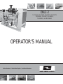
ONL2-2
For Models: NL1064D, NL1064T1, NL1064T2,
NL1064H1, NL1066T, NL1066H1,
NL1066H2, and NL1066H3
OPERATOR’S MANUAL
Marine Generators | Marine Diesel Engines | Land-Based Generators

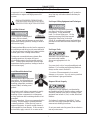
Diesel engine exhaust and some of its constitu-
ents are known to the State of California to cause
cancer, birth defects, and other reproductive harm.
— CALIFORNIA —
Proposition 65 Warning:
Northern Lights
4420 14th Avenue N.W.
Seattle, WA 98107
Tel: (206) 789-3880
Fax: (206) 782-5455
Copyright ©2013 Northern Lights, Inc.
All rights reserved. Northern Lights™, and
the Northern Lights logo are trademarks of
Northern Lights, Inc.
Printed in U.S.A.
PART NO.: ONL2-2 7/13

ONL2-2 7/13
1
Read this operator's manual thoroughly before starting to operate your equipment.
This manual contains information you will need to run and service your new unit.
OPERATOR'S MANUAL
#ONL2-2 for Models:
NL1064D, NL1064T1, NL1064T2, NL1064H1,
NL1066T, NL1066H1, NL1066H2, and NL1066H3
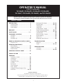
INTRODUCTION ....................................................2
Models Included .................................................2
Model Numbers ..................................................2
Serial Numbers ...................................................2
WARRANTY ..........................................................3
SAFETY RULES ..................................3 - 7
COMPONENT LOCATIONS
NL1064T2 ...........................................................8
NL1066T .............................................................9
NL1066H2, H3 ................................................ 10
ENGINE & GENERATOR CONTROL PANELS
Series 3B & 1B .................................................11
OPERATING PROCEDURES
Before Starting ................................................. 12
Shutdown Procedures ...................................... 12
Break-In Period ................................................ 13
SERVICING SCHEDULE CHART ................. 14
SERVICE RECORD ......................................... 15
SERVICING
Lubrication - General ....................................... 16
Checking Oil .................................................... 16
Oil Changes ..................................................... 16
Changing Oil Filter .......................................... 16
Air Filter .......................................................... 16
Belt Tension ..................................................... 17
Valve Clearances .............................................. 18
Fuels - General ................................................. 19
Crankshaft Vibration Damper (6 Cyl.) ............ 20
Fuel Filters ............................................... 19 - 20
Proprietary Information
This publication is the property of Northern Lights, Inc.
It may not be reproduced in whole or in part without the written permission of Northern Lights, Inc.
© Northern Lights, Inc. All rights reserved. Litho U.S.A. Publication number ONL2-2 7/13
Table of Contents
Bleeding the Fuel System ........................ 20 - 22
Injection Pump ......................................... 22 - 25
Turbocharger .................................................... 25
Turbo Boost ..................................................... 25
Cooling System - General ................................ 25
Engine Coolant Specifi cations ................. 26 - 27
Cooling System Flushing ......................... 27 - 28
Generator Ends ................................................ 28
Electrical System - General ............................. 28
Booster Batteries .............................................. 28
Battery Care ..................................................... 29
Winterizing / Out-of-Service ........................... 29
TROUBLESHOOTING
Electrical .......................................................... 30
Engine ...................................................... 31 - 32
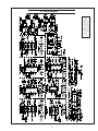
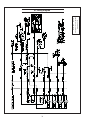
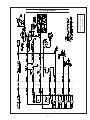
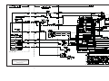
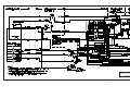
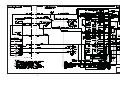
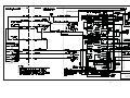
WIRING DIAGRAMS
AC Wiring ........................................................ 33
DC Wiring ................................................ 34 - 40

ONL2-2 7/13
2
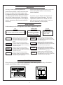
Servicing of marine engines and generator sets
presents unique problems. In many cases boats cannot
be moved to a repair facility. Marine engines cannot
be compared to the servicing of automobiles, trucks or
even farm equipment. Failures often occur in remote
areas far from competent assistance. Marine engines
are taxed far more severely than auto or truck engines;
therefore, maintenance schedules must be adhered to
more strictly.
Failures begin with minor problems that are overlooked
and become amplifi ed when not corrected during
routine maintenance.
As operator, it is your obligation to learn about your
equipment and its proper maintenance. This is not a
comprehensive technical service manual. Nor will it
make the reader into an expert mechanic. Its aim is to
aid you in maintaining your unit properly.
Introduction
D, T, H
NL - Northern Lights industrial generator set
Model number
106 mm bore, 4 Cylinder
or
106 mm bore, 6 Cylinder
Model Numbers
Model numbers give the unit's application, block model, aspiration, and RPM:
D - Naturally aspirated
T - Turbocharged
H - High output
++
Northern Lights
®
naturally aspirated,1800
RPM industrial diesel generator set with a
John Deere Powertech Tier II 4045 engine
block with a mechanically controlled fuel
system.
NL
1064 or 1066
=
=
Northern Lights
®
turbocharged industrial
generator set with a John Deere Powertech
Tier II 4045 engine block with a mechanically
controlled fuel system.
Northern Lights
®
turbocharged industrial
generator set with a John Deere Powertech
Tier II 4045 engine block with an electronically
controlled fuel system.
Northern Lights
®
turbocharged industrial
generator set with a John Deere Powertech
Tier II 4045 engine block with an electronically
controlled fuel system, high output.
Northern Lights
®
turbocharged industrial
generator set with a John Deere Powertech
Tier II 6068 engine block with an electronically
controlled fuel system.
Northern Lights
®
turbocharged industrial
generator set with a John Deere Powertech
Tier II 6068 engine block with an electronically
controlled fuel system, high output.
Northern Lights
®
turbocharged industrial
generator set with a John Deere Powertech
Tier II 6068 engine block and an electronically
controlled fuel system, high output.
Northern Lights
®
turbocharged industrial
generator set with a John Deere Powertech
Tier II 6068 engine block and an electronically
controlled fuel system, high output.
NL1064T1
=
=
=
Serial Numbers
When referencing Alaska Diesel Electric equipment by serial number, please refer only to the number
stamped on the Northern Lights
®
serial number plate.
NL1064T2
=
=
NL1066H1
NL1064H1
NL1064D
=
NL1066T
NL1066H2
NL1066H3

ONL2-2 7/13
3
A warranty registration certifi cate is supplied
with your set. The extent of coverage is described
in the Limited Warranty Statement. We
recommend that you study the statement carefully.
NOTE: If the warranty is to apply, the servicing
instructions outlined in this manual must be
followed. If further information is needed, please
contact an authorized dealer or the factory.
Warranty
Safety Rules
Revised 7/10/13
NOTICE: Accident reports show that careless use of engines causes a high percentage of accidents.
You can avoid accidents by observing these safety rules. Study these rules carefully and enforce them on the job.
IMPORTANT SAFETY INSTRUCTIONS.
Electromagnetic equipment, including generator sets
and their accessories, can cause bodily harm and
life threatening injuries when improperly installed,
operated or maintained. To prevent accidents be aware
of potential dangers and act safely.
READ AND FOLLOW ALL SAFETY
INSTRUCTIONS IN THIS MANUAL,
PRIOR TO THE INSTALLATION
OF ANY GENERATOR SET OR
ACCESSORY. KEEP THESE
INSTRUCTIONS FOR FUTURE
REFERENCE.
Recognize Safety Symbols and Instructions
In addition to the information found in this section, this
operator’s manual uses three different signal words to
outline potential dangers of a specifi c nature.
Follow All Safety Instructions
Carefully read and understand
all safety messages in this
manual and on your machine’s
safety signs. Keep signs in good
and clean condition. Replace
missing or damaged signs. Be
sure new equipment components and repair parts
include the current safety signs. For replacement signs,
proper placement of safety signs or clarifi cation on any
safety issue, consult your Northern Lights dealer or the
factory.
There can be additional safety information contained
on parts and components from outside suppliers
that is not reproduced in this manual. Consult the
suppliers for additional safety information.
Learn how to operate the machine and how to use
the controls properly. Only trained personnel should
operate machines, or work on or around them.
Keep you machine in proper working condition.
UNAUTHORIZED MODIFICATIONS TO THE
MACHINERY MAY IMPAIR ITS FUNCTION
AND SAFETY PARAMETERS.
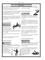
Prevent Bypass and Accidental Starting
Do not start engine by shorting
across start terminal. Engine will
start if normal circuitry is bypassed,
creating a hazard by runaway
machinery.
Start engine only from operator’s station.
Handle Fuel Safely - Avoid Flames
Diesel is highly fl ammable and should be treated
with care at all times. Do not refuel while smoking
or when near sparks or open fl ame.
ALWAYS STOP ENGINE
BEFORE FUELING
MACHINE. Always fi ll
portable fuel tank outdoors.
Never fuel a hot engine.
DANGER indicates a hazardous situation which, if
not avoided, will result in death or serious injury.
WARNING indicates a hazardous situation which, if
not avoided, could result in death or serious injury.
CAUTION indicates a hazardous situation which,
if not avoided, could result in minor or moderate
injury.

ONL2-2 7/13
4
Safety Rules
updated 2/23/12
Operating equipment requires the full attention of
the operator. Do not use radio or music headphones
while operating machinery.
Practice Safe Maintenance
Understand all service procedures
before starting work. Keep area clean and dry.
Never lubricate, service, or adjust machine while it is
in operation.
Keep hands, feet and clothing away from power-
driven equipment. When shutting down an engine,
disengage all power and operator controls. Allow
the engine to cool completely before beginning any
service work.
Securely support any machinery elements that must
be raised for service work with support or lifting
machinery specifi cally intended for that purpose.
Keep all parts in good conditions and properly
installed. Fix damage immediately. Replace any
worn or broken parts. Remove any build up of
grease, oil or debris.
Disconnect battery ground cable (-) before making
any adjustments or service work.
Stay Clear of Rotating Drivelines
Entanglement in rotating drivelines can cause serious
injury or death. Keep shields in place at all times.
Make sure that rotating shields turn freely in pace
with the drivelines.
Do not wear loose fi tting equipment around rotating
drivelines. Stop the engine and make sure that all
moving parts have stopped
before making any adjustments,
connections, or performing
any other type of service to
the engine or other driven
equipment.
Prevent accidental discharge of starting fl uids by
storing all cans in a cool, safe place, away from sparks
or open fl ame. Store with cap securely on container.
Never incinerate or puncture a fuel container.
Prevent fi res by keeping machine clean of accumulated
trash, grease and debris. Always clean any spilled fuel
as swiftly as possible. Do not store oily rags, which
can ignite and burn spontaneously.
Be prepared if a fi re starts. Keep a fi rst aid kit and fi re
extinguisher handy. Keep emergency contact numbers
for fi re department, doctors, ambulance and hospital
near the telephone.
Service Machines Safely
Do not wear a necktie, scarf,
necklace, rings or other
jewelry, or any loose clothing
when working near moving
parts. Tie long hair behind your head. If any of these
items get caught in moving machinery, severe injury or
death could result.
Check for any loose electrical connections or faulty
wiring.
Look completely around engine to make sure that
everything is clear before starting.
Wear Protective Clothing
To prevent catching anything in moving machinery,
always wear close fi tting clothes and safety equipment
appropriate to the job.
Prolonged exposure to loud noise can cause hearing
loss or impairment.
Wear suitable authorized
hearing protection, such
as earmuffs or plugs to
protect against loud noises.

ONL2-2 7/13
5
Safety Rules (Continued)
Updated 2/23/12
Install all Safety Guards
Direct contact with rotating
fans, belts, pulley and drives
can cause serious injury.
Keep all guards in place at all
times during engine operation.
Wear close-fi tting clothes. Stop the engine and be
sure all fans, belts, pulleys and drives are stopped
before making adjustments, connections, or cleaning
near fans and their components.
Do not allow anything on your person to dangle into
or come in contact with a moving fan, belt, pulley or
drive. Fans can act as vacuums and pull materials
up from below, so avoid that area as well while in
service.
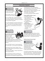
Safe Battery Handling
Prevent Battery Explosions
Battery gas is highly
fl ammable. Battery
explosions can cause severe
injury or death. To help
prevent battery explosions, keep sparks, lighted
matches and open fl ame away from the top of battery.
When checking battery electrolyte level, use a
fl ashlight.
Never check battery charge by contacting the posts
with a metal object. Use a volt-meter or hydrometer.
Frozen batteries may explode if charged. Never
charge a battery that has not been allowed to warm to
at least 16
o
C (60
o
F).
Always remove grounded (-) battery clamp fi rst and
replace ground clamp last.
S
ulfuric acid in battery electrolyte is poisonous and
strong enough to burn skin, eat holes into clothing and
other materials, and cause blindness if splashed into eyes.
To Avoid Hazards:
• Fill batteries only in well-ventilated areas.
• Wear appropriate eye protection and rubber gloves.
• Never use air pressure to clean batteries.
• Wear appropriate ventilation equipment to avoid
inhaling fumes when adding electrolyte.
• Do not spill or drip electrolyte.
• Use correct jump-start procedure if required.
If acid is spilled on skin or in eyes:
1. Flush skin with water.
2. Apply baking soda or lime to
help neutralize acid.
3. Flush eyes with water for
15-30 minutes.
4. Get medical attention
immediately.
If acid is swallowed:
1. DO NOT induce vomiting.
2. Drink large amounts of
water or milk, without
exceeding 2 liters
(2 quarts)
3. Get medical attention immediately
Battery posts, terminals, and related accessories
can contain lead and lead compounds, chemicals
known to the State of California to cause cancer and
reproductive harm. Wash hands after handling.
Handle Chemical Products Safely
Direct exposure to hazardous
chemicals can cause serious injury.
Among the potentially hazardous
chemicals that may be used
with Northern Lights
products are lubricants,
coolants, paints and adhesives.
All potentially hazardous chemicals come with a Material
Data Safety Sheet (MSDS). The MSDS provides specifi c
details on chemical products, including physical hazards,
safety procedures and emergency response techniques

ONL2-2 7/13
6
Safety Rules (Continued)
Updated 2/23/12
Read and understand the MSDS for each chemical before
you start any job that includes it. Follow the procedures
and use appropriate equipment exactly as recommended.
Contact your Northern Lights dealer or Northern Lights
factory for MSDS’s used on Northern Lights products.
Work in Well Ventilated Areas
Exhaust fumes from engines contain carbon monoxide
and can cause sickness or death. Work in well ventilated
areas to avoid prolonged exposure to engine fumes. If it
is necessary to run an engine in an enclosed area, route
the exhaust fumes out of the area with an approved, leak
proof exhaust pipe extension.
Remove Paint Before Welding or Heating
Hazardous fumes can be generated
when paint is heated by welding,
soldering or using a torch. To avoid
potentially toxic fumes and dust,
remove paint before heating.
•
Remove paint a minimum of 100
mm (4 in.) from the
area that will be affected by heat.
•
If paint cannot be removed, wear an approved respirator.
• If you sand or grind paint, use an approved respirator.
• If you use solvent or paint stripper, remove stripper
with soap and water before welding. Remove
solvent or paint stripper containers from the area.
• Allow at least 15 minutes for fumes to disperse
before welding or heating.
Do not use a chlorinated solvent in an area where welding
will occur. Work only in areas that are well ventilated.
Dispose of paint and solvent properly.
Service Cooling System Safely
Opening a pressurized cooling
system can release explosive
fl uids and causing serious burns.
Before opening any pressurized
cooling system, make sure the
engine has been shut off. Do not remove a fi ller cap
unless it
is cool enough to comfortably grip with bare
hands. Slowly loosen cap to relieve pressure before
opening fully.
Avoid High Pressure Fluids
Relieve pressure prior to
disconnecting pressurized lines.
Escaping fl uid under pressure
can penetrate the skin causing
serious injury. Always relieve pressure before
disconnecting hydraulic or other pressurized lines.
Tighten all connections fi rmly before re-applying
pressure.
If searching for leaks, use a piece of cardboard.
Always protect your hands and other body parts from
high-pressure fl uids.
If an accident occurs, see a doctor immediately. Any
high pressure spray injected into the skin must be
removed within a few hours to prevent the risk of
gangrene or other infection.
Avoid Heating Near Pressurized Fluid Lines
Flammable spray can be generated
by heating near pressurized fl uid
lines, resulting in severe burns and
bodily injury. Pressurized lines
can rupture when heat goes beyond the immediate
fl ame area. Do not weld, solder or use a torch or
open fl ame near pressurized lines or other fl ammable
fl uids.
Do Not Open High-Pressure Fuel System
Many Northern Lights engines use high-pressure
fuel injection. High-pressure fl uid remaining in fuel
lines can cause serious injury. Do not disconnect or
attempt any repair of fuel lines, sensors, or other

ONL2-2 7/13
7
Safety Rules (Continued)
Updated 2/23/12
material containing asbestos. Keep all bystanders
away from any area where asbestos dust may be
generated.
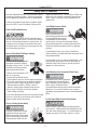
Use Proper Lifting Equipment and Techniques
Lifting heavy components incorrectly
can cause severe injury or damage
to machinery. Avoid unbalanced
loads. Do not use lifting eyes. Lift the
generator set using lifting bars inserted
through the lifting holes on the skid.
Follow all recommended removal and installation
procedures in this and associated Northern Lights
manuals.
Use Proper Tools
Makeshift tools and procedures
can create safety hazards.
Always use appropriate tools for
the job.
Use power tools only to loosen threaded parts and
fasteners. For loosening and tightening hardware,
always use the correct sized tools.
Do not use US measurement tools on metric
fasteners, or vice versa. Use only service parts that
meet Northern Lights specifi cations.
Dispose of Waste Properly
Disposing of waste improperly can threaten the
environment and lead to unsafe working conditions.
Potentially harmful waste used in Northern Lights
equipment can include oil, fuel, coolant, fi lters and
batteries.
Use leakproof containers to drain fl uid. Do not
use food or beverage containers that may mislead
someone into drinking from them.
Do not pour waste onto the ground, down a drain or
into any water source.
components between the high-pressure fuel pump
and nozzles on engines with high pressure fuel
systems.
ONLY AUTHORIZED TECHNICIANS
CAN PERFORM REPAIRS ON AN HIGH
PRESSURE FUEL INJECTION SYSTEMS.
Avoid Hot Exhaust
Avoid exposure to and physical
contact with hot exhaust
gases. Exhaust parts and streams can reach high
temperatures during operation, leading to burns or
other serious injury.
Cleaning exhaust fi lters can also lead to exposure to
hot exhaust gas and the injury risk associated with
it. Avoid exposure to and physical contact with hot
exhaust gases when cleaning exhaust fi lters.
During auto or manual/stationary exhaust fi lter
cleaning operations, the engine will run at
elevated temperatures for an extended period of
time. Exhaust parts and streams can reach high
temperatures during operation, leading to burns or
other serious injury.
Avoid Harmful Asbestos Dust
Inhaling asbestos fi bers may cause
lung cancer. Avoid breathing any
dust that may be generated when
handling components containing
asbestos fi bers, including some
gaskets.
The asbestos used in these components is usually
found in a resin or otherwise sealed. Normal
handling of these components is not dangerous,
as long as airborne dust containing asbestos is not
generated.
Avoid creating dust. Never use compressed air for
cleaning. Avoid brushing or grinding materials
containing asbestos. When servicing, wear an
approved respirator. A special vacuum cleaner is
recommended to clean asbestos. If this vacuum is
not available, apply a mist of oil or water on the

ONL2-2 7/13
8
General Policy
To avoid dangerous or hazardous situations, refrain from
any of the following:
• Removing or bypassing a guard or other safety device
• Placing any part of your body in a position where you
could be caught by moving machinery.
• Cleaning or oiling machinery when in operation.
• Adjusting circuits, chillers, pumps, air handlers, valves,
circuit breakers or fans while in operation.
• Working on piping or high pressure systems.
Lock Out/Tag Out Instructions -
Electrical Equipment
Be sure the equipment’s ON/OFF switch is in the OFF
position and is unplugged from any electrical source before
attempting to perform any type of work on the equipment.
Obtain an electrical plug cap cover with a lockset. Secure
the plug terminal end using the electrical plug lockout cap.
Lock the cap and retain the key.
If the equipment is directly wired into an electrical box with
a shut off switch, obtain a lock pad and/or the appropriate
colored tags and place the lock and tag through the shut
off lever. Retain the key until the repair is completed and
the machine is safe to start. Be certain the shut off lever
is in the OFF position before restarting. NEVER give a
lock out key to unauthorized personnel.
If the equipment is directly wired into an electrical box
without a shut off switch and lock out capability, then a
circuit breaker lock out will be required. Obtain a circuit
lock and tag set. Install the lock onto the circuit breaker
box. Ensure the unit ON/OFF switch is in the OFF position
before restarting.
Lock Out/Tag Out Instructions -
Pneumatic and Hydraulic Equipment
For servicing pneumatic and hydraulic equipment, the
following additional procedures must be implemented,
following completion of lock out/tag out procedures for
the unit to be serviced:
Shut off air, water or supply valves at the equipment to
be serviced.
Check the local bleed-off point for completed release of
pressurized air, water or oil.
If shutting off of air, water or other material cannot be
achieved at the local supply valve, shut off valves further
back in the system and re-check the bleed-off point until
complete shut-off is achieved.
Affi x a DO NOT OPERATE tag to each valve handle that
requires shut off. Each DO NOT OPERATE tag must be
signed and dated by the authorized technician servicing
the equipment.
Lock Out/Tag Out Instructions -
Air Hose Connected Pneumatic Equipment
Equipment connected to the compressed air system
through an air hose with a detachable fi tting must be
shutdown and unplugged. Excess air must be bled prior
to removing the air hose, prior to any maintenance or
repair activities.
Affi x a DO NOT OPERATE tag to the air hose near the
detachable fi tting. Each DO NOT OPERATE tag must be
signed and dated by the authorized technician servicing
the equipment. Check that the equipment cannot be
operated by activating the ON switch.
Stored Energy
Immediately after applying Lock Out or Tag Out devices,
ensure that all potentially hazardous stored or residual
energy is relieved, disconnected, restrained and otherwise
rendered safe.
Verifi cation of Isolation
Verify the machinery or equipment is actually isolated and
de-energized prior to beginning work on a machine or on
equipment that has been locked out.
Restarting Procedures
Follow the procedures below prior to restoring energy:
• Ensure that all machinery or equipment is properly
reassembled. Inspect the machinery or equipment to
verify non-essential items have been removed.
• Ensure that all personnel are safely outside danger
zones. Notify personnel that lock out/tag out devices have
been removed and energy will be reapplied.
• Only authorized personnel may remove lock out/tag out
devices or notices.
Scope
During maintenance, repairs or retooling of a Northern Lights generator set, simply turning the machine off or unplugging
it while it is being worked on does not give enough protection to others who are not performing the maintenance or
repair. Many serious accidents happen when someone thought the machine was turned off, or all of its energy was
safely blocked or released.
Lock Out / Tag Out Procedures
Added 2-24-12

ONL2-2 7/13
9
Notes

ONL2-2 7/13
10
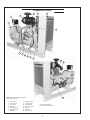
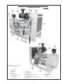
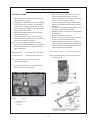
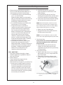
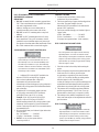
1. Junction Box
2. Control Panel
3. Air Cleaner
4. Rain Cap
5. Exhaust Elbow
6. Radiator Shroud
7. Alternator
8. Vibration Mount
9. Lube Oil Filter
10. Fuel Manifold
11. Lube Oil Dipstick
12. Starter
13. Fuel Filter
14. Turbocharger
15. Exhaust Manifold
16. Electronic Control Unit
Component Locations
Figures 1 & 2: NL1064T2 (Electronically
Controlled Fuel System)
1
2
3
4
5
6
7
8
9
10
11
12
13
14
16
15

ONL2-2 7/13
11
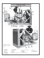
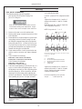
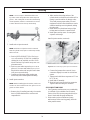
Component Locations
1. Junction Box
2. Control Panel
3. Air Cleaner
4. Rain Cap
5. Exhaust Elbow
6. Low Coolant Level Gauge
(optional)
7. Radiator Shroud
Figure 3 & 4: NL1066T (Electronically
Controlled Fuel System)
1
2
3
4
5
6
7
8
9
10
11
12
13
14
15
16
2
17
18
8. Alternator
9. Vibration Mount
10. Lube Oil Filter
11. Low Oil Level Gauge (optional)
12. Lube Oil Dipstick
13. Fuel Filter/ Water Separator (optional)
14. Fuel Filter
15. Turbocharger
16. Exhaust Manifold
17. Starter
18. Electronic Control Unit

ONL2-2 7/13
12
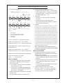
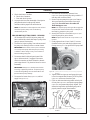
1. Junction Box
2. Control Panel
3. Air Cleaner
4. Rain Cap
5. Turbocharger
6. Exhaust Elbow
7. Radiator Shroud
8. Low Coolant Level
Gauge (optional)
9. Alternator
10. Oil Filter
11. Dipstick
12. Low Oil Level Gauge (optional)
13. Fuel Filter/ Water Separator
(optional)
14. Fuel Filter
15. Fuel Manifold
16. Secondary Fuel Filter
Component Locations
Figures 5 & 6: NL1066H2, H3
(Electronically Controlled Fuel
System)
6
4
2
1
3
5
7
8
17
18
11
9
16
12
14 10
13
15
19
17. Starter
18. Exhaust Manifold
19. Vibration Mounts
17

ONL2-2 7/13
13
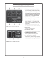
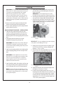
Northern Lights Control Panels
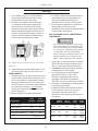
Figure 7: Series 3-B Generator Control Panel
Figure 8: Series 1-B Generator Control Panel
1. SHUTDOWN BYPASS-PREHEAT SWITCH
Two functions are built into this switch: the preheat-
ing of the engine, and bypassing of the engine safety
shutdown circuit. Hold switch in the ON position
10 - 20 seconds before starting the engine, and con-
tinue holding on during engine cranking. Release the
switch as soon as the engine is running. Holding the
switch on too long can burn out the heater element.
2. ENGINE CONTROL SWITCH
To start the engine, hold this switch in the START
position until the engine is running.
After the engine starts, release the switch and it will
return to RUN position. To stop the engine, hold the
switch in the STOP position until the engine has com-
pletely stopped.
NOTE: The rocker switch is used on Series 1 panels
only, and has a light that glows when the set is running.
3. HOUR METER
Keeps track of engine running time.
4. OIL PRESSURE GAUGE
Shows the oil pressure in the engine lubricating system.
5. ENGINE TEMPERATURE GAUGE
Registers the temperature of the engine coolant.
6. D.C. VOLTMETER OR AMMETER
When the engine is stopped, the voltmeter indicates the
condition of the battery. When the engine is running, the
voltmeter indicates the voltage output of the alternator.

ONL2-2 7/13
14
Operating
1. Check Gauges Often: Oil pressure must be above
29 PSI (if not above 15 PSI within 5 seconds of
starting, the engine should be stopped and the
problem should be explored). Normal oil pres-
sure is 50 PSI at rated load speed (1800 to 2500
RPM). Oil temperature should be 115
0
C (240
0
F) for
normal operating temperature. Coolant temperature
should be 82 - 94°C (180 - 202°F) for electronically
controlled fuel systems, 90 -100°C (194 -212°F)
for mechanically controlled fuel systems. The D.C.
voltmeter should read between 13 and 14 volts (26-
28 volts, 24 volt systems).
2. Check AC voltage and frequency meters (Series 4
Panel). If gauges deviate from normal levels, shut
down the set and investigate.
3. Check belt for good alignment.
4. Let the unit run unloaded for a three to fi ve minute
warm-up period before applying load.
5. Do not add full electrical load until engine is at
maximum operating temperature.
6. If the air temperature is below -10°C (14°F) use an
engine block heater.
Shutdown
1. Turn the Engine Control Switch to the OFF position.
2. Close the fuel valves, and put the battery switch
in the OFF position if the unit will be off for an
extended period.
Do not turn the battery switch to OFF while the
engine is running.
SHUTDOWNS AND ALARMS
1. Your unit is fi tted with a system to protect it from
high water temperature or low oil pressure.
a. Generator sets have shutdown systems to stop the
engine. They have no warning horns.
b. Other alarms and shutdowns are available as
optional equipment.
NOTE: Do not rely on your warning or shutdown
system to the exclusion of careful gauge monitoring.
Watching your gauges can prevent damage to the unit
and dangerous power losses.
2. Do the following when your shutdown system is
activated:
a. Check the coolant temperature gauge. If the
temperature is above 205°F (97°C), shut off the
engine immediately.
Operating Procedures
BEFORE STARTING
1. Check the water level by removing the pressure
cap from the expansion tank. In order to give the
cooling water room to expand, the level should be
about 1 3/4 in. (4-5 cm) below the fi ller cap sealing
surface when the engine is cold. When fi lling with
coolant, the venting cock on top of the turbocharger
should be opened to ensure that no air pockets form
in the cooling system.
Use protective clothing and open
the fi ller cap carefully when the engine is warm
to prevent burns.
2. Check the oil level in the crankcase with the dipstick.
The oil level should be in the “waffl ed area” or on or
below “full”. Always add the same viscosity of oil
as is already in the crankcase.
3. Check the fuel tank level and open any fuel valves.
4. Disengage clutch, if equipped.
5. Close the seacock, check and clean the strainer and
reopen the seacock.
6. Place the battery switch in the ON position.
NOTE: The battery switch must always be kept ON
while the engine is running. If the switch is turned
OFF while the engine is running, the battery charging
regulator could be ruined.
Starting
1. While holding the Shutdown Bypass switch in the
ON position, push the Engine Control switch to the
START position.
2. As soon as the engine starts, release both switches.
Do not crank the starter for more than 20 seconds.
3. If the engine fails to start the fi rst time, be sure the
starter has stopped before re-engaging.
4. Operate engine at or below 1200 RPM with no-
load for 1 to 2 minutes to ensure proper lubrication.
When operating at below freezing temperatures
extend this period to 2 to 4 minutes.
NOTE: If there is a governor locked at a specifi c
speed on the generator set, there may not be a slow
idle function, so in that case operate the engine at
high idle for 1 to 2 minutes before adding load. If
the stand-by generator set is loaded as soon as it
reaches rated speed, this procedure would not apply.
revised 2-24-12

ONL2-2 7/13
15
Operating Procedures
Do not remove the water fi ll cap of an overheated
engine. Escaping high temperature steam can cause
severe burns. Allow the engine to cool and then
remove the cap slowly, using
protective clothing.
b. Use the Trouble Shooting Guide on pages 27- 29
to isolate the cause of the overheat.
c. Make repairs and restart after the temperature
gauge registers below 180°F (83°C).
d. Watch the temperature gauge regularly and turn
off the unit if the temperature rises above 200°F
(94°C). Repeat the troubleshooting process.
3. If the shutdown is activated and the temperature
gauge shows temperature within normal temperature
range:
a. Check the engine crankcase oil level.
b.
If the oil level is low, fi ll with recommended lubricating
oil and restart. Do not add oil above the crosshatch
pattern or “full” mark. Watch the oil pressure gauge
carefully and shut off the engine if it does not show a
normal reading after a few seconds of operation.
c. If the oil level was normal, DO NOT restart the
engine. Call your Northern Lights or Lugger
dealer for assistance.
BREAK-IN PERIOD
1. The fi rst 100 hours on a new or reconditioned engine
are critical to its life and performance.
2. Operate the engine under various conditions,
particularly heavy loades with minimal idling, to
help seat engine components properly.
3. Constantly check the engine temperature and oil
pressure gauges.
4. Oil consumption is greater during break-in as piston
rings and cylinder liners take time to seat.
5. Break-In Oil Changes: Change engine oil and fi lter
at 50 hours. Change oil and fi lter again at 100 hours
(Consult Lubricants Section for oil recommendation).
Cold Weather Operation
1. Cold weather starting aids are required for air
temperatures below 0°C (32°F). These might
include intake air heaters, coolant heaters, fuel
heaters, or ether injectors. Additional starting aids
may be needed in temperatures below -30°C
(-22°F) or above 1500 m (5000 ft) in altitude.
Do not use starting fl uid on engines with air
intake heaters or glow plugs. Ether
injector starting fl uid is highly fl ammable and
may explode. Do not incinerate or puncture a
starting fl uid container.
2. After starting an electronically controlled fuel
system engine without an air intake heater,
manually activate ether injectors if required.
3. On electronically controlled fuel systems the
air intake heater activates automatically by the
ECU. The preheater indicator light (above the
key switch) should light up when the switch is on.
The light is briefl y on in warm weather. In cold
weather the light stays on during the automatic
operation of the air heater; do not crank the engine
until the light turns off. The time might vary
according to the ambient temperature.
revised 1-10-13

ONL2-2 7/13
16
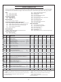
The Servicing Schedule Chart below shows the service schedule required for proper maintenance of your marine engine
or generator set. More detailed coverage of each Service Point (SP) is listed on the page noted in the ‘page’ column.
DAILY:
SP1 Check oil level in engine
SP8 Check primary fuel fi lter
SP15 Check cooling water level
AFTER FIRST 50 HOURS:
SP2 Change engine oil
SP3 Change lube oil fi lter
EVERY 50 HOURS:
SP21 Check electrolyte in batteries
AFTER FIRST 100 HOURS/ EVERY TWO WEEKS
5
:
SP2 Change engine oil after fi rst 100 hrs., then check every 2 wks.
SP3 Change oil fi lter after fi rst 100 hrs., then check every 2 wks.
SP4 Check air cleaner valve & restriction indicator gauge
6
SP7 Check crankshaft vibration damper
7
SP15 Check coolant level
EVERY 250 HOURS
SP2&3 Change engine oil & fi lters (fuel fi lter/water bowl)
EVERY 500 HOURS / YEARLY:
SP4 Replace air cleaner
SP5 Check V-belt condition
SP9 Change primary fi lter element (Racor)
SP10 Change secondary fuel fi lter
SP11 Check injectors
SP14 Check turbocharger boost pressure
SP16 Check cooling system
SP22 Check the state of the charge of the batteries
SP25 Check engine mounts
SP26 Clean crankcase vent tube
SP27 Check air intake hoses
SP29 Check electrical ground connection
SP30 Check engine speeds
EVERY 2000 HOURS:
SP6 Check & adjust valve clearance
SP7 Check crankshaft vibration damper
SP12 Check fuel injection pump
SP16 Flush cooling system
SP18 Check and clean radiator
SP23 Test thermostats
SP31 Adjust variable speed (droop) (Mechanical Engines Only)
1) Change the oil and fi lter before the fi rst 100 hours of operation during engine
break-in.
2) Perform all maintenance once a year even if hour level has not been reached.
3) Consult manufacturer's maintenance schedule, note on chart.
4) Whenever necessary.
Service Schedule Chart
SERVICE 50 100 250 500 2000
POINT PAGE OPERATION DAILY Hours Hours Hours Hours Hours
ENGINE:
SP1 13 Check oil level •
SP2 13 Change engine oil 1) 2) • • •
SP3 13 Change lube oil fi lters 1) 2) • • •
SP4 13 Check air cleaner valve & change element 2) 4) 6) ••
SP5 Check belt condition 2) •
SP6 15 Check valve clearances 2) •
SP7 17 Check crankshaft vibration damper 7) •
SP25 Check engine mounts •
SP27 Check air intake hoses •
SP30 Check engine speeds •
FUEL SYSTEM:
SP8 16 Check primary fi lter (Racor) 3) •
SP9 16 Change primary fi lter element (Racor) 3) 4) •
SP10 17 Change secondary fuel fi lter 2) 4) •
SP11 Check injectors 8)
SP12 Check fuel injection pump •
TURBOCHARGER:
SP13 22
Check air, oil & cooling water lines for leakage
2)
•
SP14 22 Check boost pressure •
COOLING SYSTEM:
SP15 24 Check cooling water level •
SP16 24 Check and fl ush cooling system 2) • •
SP18 Check and clean radiator
•
ELECTRICAL SYSTEM:
SP21 26 Check electrolyte level in batteries 2) 4) •
SP22 26 Check condition of batteries with hydrometer 2) •
SP23 Test thermostats •
SP29 Check electrical ground connection •
5) Operate engine at rated speed with 50-70% load for 30 minutes at
least.
6) Replace air cleaner element when restriction indicator shows
vacuum of 625 mm (25 in.) H
2
0.
7) Replace damper every 4500 hours or after 60 months.
8) Check at 5000 hours.

ONL2-2 7/13
17
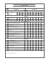
Service
Point
HOURS/DATE
Service Record
OPERATION
50 HOURS
SP21 Check electrolyte
in batteries
250 HOURS
SP2 Change engine oil*
SP3 Change lubricating oil fi lters*
500 HOURS
SP4 Check air cleaner*, replace as needed
SP5 Check belt condition
SP9 Change primary fuel fi lter element
SP10 Change secondary fuel fi lter
SP11 Check injectors
SP13 Check turbocharger air, oil & cooling lines for leakage
SP14 Check turbocharger boost pressure
SP16 Check cooling system
SP22 Check state of charge of batteries
2000 HOURS
SP6 Check valve clearance
SP7 Check crankshaft vibration damper
SP12 Check fuel injection pump
SP16 Flush cooling system
SP18 Check radiator
* After fi rst 50 and then 100 hours.

ONL2-2 7/13
18
LUBRICATION
Break-in oil
1. Use one of the following during the fi rst 100 hours
of operation:
a. John Deere Engine Break-In Oil
b. API Service CC, CD, or CE oil
c. ACEA Specifi cation E1 or E2
2. Do not use John Deere PLUS-50 oil or engine oils
meeting API CI-4, CH-4, CG-4, CF-4, or CF-2,
ACEA E5, E4, or E3 performance levels during
the fi rst 100 hours of operation of a new or rebuilt
engine. These oils will not allow the engine to
break-in properly.
Lubrication - General
1. Use only clean, high quality lubricants stored in
clean containers in a protected area.
2. These oils are acceptable after the fi rst 100 hours:
a. API Service Catagory CI-4 or CH-4 oils.
b. ACEA Oil Sequence E4 or E5.
d. ACEA Oil Sequence E3.
3. Use the proper weight oil for your average operation
temperature, multi-viscosity diesel engine oils are
preferred. Quality and sulfur content must comply
with local existing emission regulations.
4. Some increase in oil consumption may be expected
when SAE 5W and SAE 5-20W oils are used. Check
oil level frequently.
5. Never put additives or fl ushing oil in crankcase.
SP1. CHECK ENGINE OIL LEVEL
1. Check the oil level in the crankcase, with the oil
dipstick, daily.
2. The oil level must be between the “Waffl ed area”
and the “add”. Never allow the level to go below the
“add”.
3. Always add the same viscosity of oil as is already in
the crankcase.
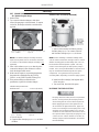
SP2. OIL CHANGES
1. Using the oil recommended above, change the engine
oil and fi lter after the fi rst 50 hours of operation, the
fi rst 100 hours and every 250 hours thereafter.
2. During intermittent cold weather operation, change oil
every 100 hours or six weeks, whichever comes fi rst.
3. Change oil at any seasonal change in temperature
when a new viscosity of oil is required.
a. Remove plug from outlet in base frame. Screw in
owner-supplied drain hose.
b. Open valve at oil pan outlet. After oil has been
drained into suitable container, close valve, remove
drain hose and replace plug in base frame outlet.
c. Refi ll engine with recommended oil.
4. Engine Lube Oil Capacity:
SP3. CHANGING OIL FILTER
1. Change the lube oil fi lter every 250 hours.
2. Use a fi lter wrench to remove old fi lter. Dispose of
fi lter in approved manner.
3. Make sure the gasket from the old fi lter is removed
and discarded.
4. Lubricate the rubber gasket on the new fi lter and screw
it on nipple until gasket meet the sealing surface.
5.
Using hands only, no wrench, tighten fi lter one-half turn
farther. Overtightening can do damage to fi lter housing.
6. Fill engine with recommended oil. Start engine and
check for leakage. Stop engine and check oil level.
Add additional oil if necessary.
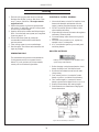
SP4. AIR CLEANER
1. Inspect air cleaner every 100 hours. Replace air
cleaner element every 500 hours.
2. Clean the rubber tube at the cleaner. Loosen the hose
clamp and the attaching strip for the cleaner.
3. Make sure the rubber tube is in good condition and
that new fi lter is absolutely clean and installed
properly.
4. Start the engine and check for leaks.
NOTE: Make absolutely sure no impurities enter the
engine while changing the element. Do not run the
engine with the air cleaner removed.
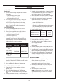
Air Single Multi
Temperature Viscosity Viscosity
Above 32°F
(0°C)
SAE-30W SAE15-40W
-10°F to 32°F
(-23°C to 0°C)
SAE-10W SAE10-30W
Below -10°F
(-23°C)
SAE-5W SAE5-20W
NL1064D,T1,T2, H1 14.7 liters 15.5 qts.
NL1066T 20.0 liters 21.1 qts.
NL1066H1,H2,H3 31.5 liters 33.3 qts.
Servicing
Page is loading ...
Page is loading ...
Page is loading ...
Page is loading ...
Page is loading ...
Page is loading ...
Page is loading ...
Page is loading ...
Page is loading ...
Page is loading ...
Page is loading ...
Page is loading ...
Page is loading ...
Page is loading ...
Page is loading ...
Page is loading ...
Page is loading ...
Page is loading ...
Page is loading ...
Page is loading ...
Page is loading ...
Page is loading ...
Page is loading ...
Page is loading ...
Page is loading ...
-
 1
1
-
 2
2
-
 3
3
-
 4
4
-
 5
5
-
 6
6
-
 7
7
-
 8
8
-
 9
9
-
 10
10
-
 11
11
-
 12
12
-
 13
13
-
 14
14
-
 15
15
-
 16
16
-
 17
17
-
 18
18
-
 19
19
-
 20
20
-
 21
21
-
 22
22
-
 23
23
-
 24
24
-
 25
25
-
 26
26
-
 27
27
-
 28
28
-
 29
29
-
 30
30
-
 31
31
-
 32
32
-
 33
33
-
 34
34
-
 35
35
-
 36
36
-
 37
37
-
 38
38
-
 39
39
-
 40
40
-
 41
41
-
 42
42
-
 43
43
-
 44
44
-
 45
45


Nothern Lights NL1064T1 User manual
- Category
- Engine
- Type
- User manual
Ask a question and I''ll find the answer in the document
Finding information in a document is now easier with AI
Related papers
-
Nothern Lights NL673L User manual
-
-
-
-
-
-
-
-
-
Other documents
-
 Northern Lights Lugger M773LW3 User manual
-
 Northern Lights M673L3 User manual
-
 Lugger L1276A User manual
-
LightIt! 30016-308 Operating instructions
-
 Northern Lights Lugger M843NW3 User manual
-
 Lugger L944D User manual
-
 Northern Lights Lugger M773LW3 User manual
-
 Lugger L1066A User manual
-
Doosan DE12T Operation & Maintenance Manual
-
P3 International P7840 User manual


