Page is loading ...

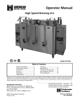
PrecisionBrew™ Barista™ Series Urns
Operator Manual
Grindmaster-Cecilware
4003 Collins Lane, Louisville, KY 40245 USA
Phone: 502.425.4776 Toll Free: 800.695.4500
Fax: 502.425.4664
Web: gmcw.com Email: info@gmcw.com
Safety Information..................2
Description ..............................3
Installation...............................3
Start up....................................5
Operation ................................6
Adjustments ............................7
Cleaning.................................11
Maintenance .........................11
Troubleshooting Guide.........13
Parts Diagram and List..........15
Wiring Diagram.....................17
Thank you for purchasing this quality urn. For your safety and the safety of others, read all warnings and the
operator manual before installing or using the product. Properly instruct all operators. Keep training records. For
future reference, record serial number here:
Table of Contents
©2016 Grindmaster-Cecilware
Printed in USA
0516 Form # AM-345-04
Part # 390-00066
Grindmaster-Cecilware provides the
industry’s BEST warranty. Visit gmcw.com
for warranty terms and conditions.
Model PB-8113E
Model PB-8103E

GB Series Cecilware
®
2
For safe and proper operation, the appliance must be placed in a stable, vertical position.
To reduce risk of serious burns or scalding, do not place hand or other body parts under dispenser or container
while product is brewing.
Always unplug unit from power supply before servicing.
Hot liquid in brew basket could cause burns. Remove with care.
Surfaces are hot and can cause burns.
CAUTION
To reduce risk of electrical shock, do not remove side panels. No user-serviceable parts inside. Repair should be
done by authorized service personnel only.
The appliance is not intended for outdoor use.
Do not clean with pressurized water or use in an area where pressurized water may be used.
Cleaning and maintenance shall be made only by properly trained persons with supervision.
This appliance is not intended for use by persons with reduced physical, sensory, or mental capabilities, or lack
of experience and knowledge, unless they have been given supervision or instruction concerning use of the
appliance by a person responsible for their safety.
Children should be supervised to ensure that they do not play with the appliance.
Do not alter or deform the power cord or plug in any way! Altering or deforming the plug may cause electrical
shock, damage unit and will void warranty.
To reduce risk of explosion or fire, do not use near combustibles.
WARNING
Safety Information
2 American Metal Ware PrecisionBrew™ Urns
Important Safety Information
This is the safety alert symbol. It is used to alert you to potential personal injury hazards. Obey all safety messages
that follow this symbol to avoid possible injury or death.
For your safety and the safety of others, read all warnings and the operator manual before installing or using
the product.
DANGER: This term warns the user of imminent hazard that will result in serious injury or death.
WARNING: This term refers to a potential hazard or unsafe practice, which could result in serious injury or death.
CAUTION: This term refers to a potential hazard or unsafe practice, which could result in minor or moderate
injury.
NOTICE: This term refers to information that needs special attention or must be fully understood.
Use only on a circuit that is properly protected and capable of the rated load.
Electronically ground the chassis.
Follow national and local electrical codes.
Do not use extension cord.
This equipment must be installed in compliance with applicable Federal, State, and/or Local plumbing codes
having jurisdiction. This product requires an approved back flow prevention water device, such as a double
check valve, to be installed between the machine and the water supply.
NOTICE

PrecisionBrew™ Urns American Metal Ware 3
Installation
Unpacking Instructions
Carefully unpack the machine and inspect immediately
for shipping damage. The packaging may contain
unattached parts. Your machine was shipped in a carton
designed to give it maximum protection in normal
handling. It was thoroughly inspected before leaving
the factory. In case of damage, contact the shipper, not
Grindmaster-Cecilware.
NOTICE: The person installing this appliance is
responsible for ensuring that electric and water
connections meet the requirements of the national
electric code, national plumbing code, and any local
ordinances.
DO NOT RUN TUBING, PIPES, CONDUIT, OR CABLE
UNDER CENTER PORTION OF BARISTA SERIES URNS.
THIS AREA MUST BE KEPT CLEAR FOR SERVICING URN
CONTROLS.
See rough-in drawings on next page for dimensions and
locations of electric and water input.
Mechanical Installation
NOTICE: This brewer should be installed by a
knowledgeable and experienced commercial
equipment installer.
1. Inspect unit to see if any damage occurred in
shipment.
2. Remove the urn from the packing material and
attach its legs.
3. Position the brewer on a strong, stable table or
counter.
4. Position urn so that the faucets drip into a drip
trough or drain receptacle of some type.
5. Level urn both front to back and left to right. The
feet are adjustable for this purpose.
CAUTION
These urns are heavy pieces of equipment. It is
recommended that moving or lifting the unit be done
by two people to avoid injury.
Description
The Barista Series Urn is a digitally controlled brewing system. This list of features will help you understand the
controls available in the brewing process.
1. Each liner has three independent batch volumes.
• Each batch volume is independent
• Each batch can be programmed with pulse brewing feature
2. Each liner has an independent coffee-hold, countdown timer.
3. Spray arms are fitted with a sensor that allows the control to detect the spray arm position.
4. The main display shows the time of day by default. A single press of the UP arrow and it displays the jacket
temperature for 5 seconds and then reverts back to time of day.
5. The control system has energy saving features that allow the urn to turn off the heater during long periods
of non-usage. Each weekday can be individually programmed with an ON time and OFF time. (i.e., if the coffee
shop opens for business at 6 am, the urn can be programmed to heat at 5 am so that it’s ready to brew by
5:30 am. If the coffee shop closes at 7 pm, the urn can be programmed to turn off the heat at 7 pm.)
6. The urn has an automatic air agitation feature that is used to keep the un-dissolved solids in the coffee in
suspension. The operator can program the “ON” and “OFF” time intervals.
7. The urn is equipped with an audio alarm. It will sound 2 beeps (2 seconds on 2 seconds off) at the end of the
brew cycle – notifying user that brewed coffee is ready to be served. And it will sound continuously for 5
minutes at the end of the specified hold time. The main control is equipped with an ALARM OFF button that
silences the system.
8. The urn has Low Temp No Brew function. If enabled, the urn will not brew unless the water temperature is
within 5ºF of set point. If enabled and one tries to start a brew before reaching the minimum brew
temperature, the display will flash “COLD” for 3 seconds and the alarm will sound 3 beeps; 1 second on, 1
second off.
9. Program mode is password protected. The default password is: “1208”

4 American Metal Ware PrecisionBrew™ Urns
:$7(5
,1/(7
(/(&75,&
,1387
:$7(5
,1/(7
(/(&75,&
,1387
Installation (continued)
Model PB8113E
Model PB8103E

PrecisionBrew™ Urns American Metal Ware 5
Installation (continued)
Water Hook-up
NOTICE: This equipment must be installed in
compliance with applicable Federal, State, and/or Local
plumbing codes having jurisdiction. This product
requires an approved back flow prevention water
device, such as a double check valve, to be installed
between the machine and the water supply. Incoming
pressure should be greater than 30 psi and not more
than 70 psi.
1. Cold or hot water (160 degrees F. maximum) may be
used. Heat input capacity is ample for the coldest
water, and cold water should be used for best
brewing results.
2. Provide shut-off valve and union in supply line near
urn.
3. Minimum inlet pressure at urn should be 30 PSI.
4. Maximum inlet pressure recommended at 70 PSI.
5. Copper flex tubing should be used for valve
connections.
6. To ensure pressure at the urn of at least 30 PSI, use
3/8" OD tubing for short runs, 1/2" OD tubing for
longer runs, and larger size tubing for unusually
long runs. Be sure other appliances will not reduce
water pressure excessively.
7. Turn on the water supply line and check for leaks.
NOTE: For the best tasting coffee, add a filtering system
to the water supply line to eliminate any taste and/or
odor from the water.
Electrical Hook-up and Start-up Procedure
NOTICE: This equipment must be installed in
compliance with applicable Federal, State, and/or Local
electrical codes having jurisdiction. Do not use
extension cords. Make sure that the outlet the urn plugs
into is grounded.
1. Check rating marking on urn nameplate to be sure
electric lines match voltage, phase, and amperage
requirements of urn. Select the proper cord and
cord grip for electrical rating of the urn. The cord
must be an oil resistant type such as SO, SOO, STO,
STOO, SEO, SJO, SJOO, SJTO, SJTOO, SJEO, HSO,
HSOO, HSJO, or HSJOO. Alternatively, flexible metal
conduit and type THHN wires may be used.
2. The terminal block and ground screw are located
behind a cover plate on the right side.
3. A neutral wire is normally required on all single
phase and on 208 Volt, 3 phase power supplies to
power the 120 VAC control circuit. In the case of
single phase, 2 wire service (no neutral), or 3 phase
3 wire service (no neutral), a separate 120 VAC cord
and plug (NEMA 5-15P) supplies 120 VAC power to
the control circuit (or for use of transformer on heat
exchange urns). This cord must be ordered
separately.
4. A fused disconnect switch should be installed near
urn.
5. Urn body MUST be grounded. A grounding
terminal is provided for this purpose.
6. Use only copper wire to connect this urn.
Start up
1. Open water supply line valve to urn.
2. Turn on or plug in the power supply to the urn.
Water compartment will begin to fill automatically.
Do not power up the urn when the water line is off.
3. Pump urns have a fast fill feature. This applies to
Triple urns and models with a suffix (P) To fill the
urn in only ten minutes on these models:
The fast fill valve is located on the underneath, rear of
the urn. The valve has a knurled knob that sticks out
past the control drawer. Turn valve to the right to close.
Turn valve to the left to open. During initial fill the valve
should be open. Close valve after initial fill so that the
valve will be closed during normal urn operation.
4. For heat exchange urns, just turn on the water. The
urn will begin to fill and then heat. It will take up
to 45 minutes to heat water, depending on inlet
water temperature, and urn heater wattage.
5. Brew and discard at least one batch of water into
each liner. Check that the fill level is correct. See the
adjustments section if changes are needed.
WARNING: ELECTRIC SHOCK HAZARD!
Installation of this appliance should be performed by
qualified service personnel only. Improper installation
could result in electrocution.
WARNING: ELECTROCUTION HAZARD!
Never use the ground conductor as a neutral. This
could cause electrocution.

6 American Metal Ware PrecisionBrew™ Urns
Operation
1. Place filter paper in brew basket with designated
amount of coffee grounds. Coffee experts
recommend from 6 to 10 ounces of coffee per
gallon of water. Make certain you have a level bed
of coffee. Consult your coffee supplier for exact
brewing specifications. Acceptable filter paper sizes
are:
Liner size Filter size Grindmaster Part #
3 gallon 18” x 6” ABB3WP
2. Replace cover. Lift and rotate the spray arm to
position the nozzle in the hole on the basket cover.
3. Press the batch size desired on the liner that the
spray arm is set to brew in.
• The timer display for the batch will flash “S” or
“M” or “L”; depending on which batch size
button was pressed.
• To stop the brew at any time, press any of the
three batch buttons for that liner.
• If the spray arm is not pointed to the same liner
in which the batch button is pressed, the display
will show “ARM”. You will need to move the
spray arm to the correct position, or press the
batch size on the liner that the spray arm is set
to brew in.
•
If after pressing a batch size, the display
momentarily shows “COLD”, it means the water
is not hot enough to brew. Wait for a few minutes
and try again. To check the water tank
temperature press the UP arrow button once and
the tank temperature will display for 5 seconds.
4. The brew cycle takes from 1 to 6 minutes depending
on the batch size. When the brew is finished, allow
one to four minutes for the coffee to drain from the
basket. Drain time is dependent on the amount of
coffee grounds used.
5. When the drip period is complete, center the spray
arm and remove the basket to throw away the
grounds. Replace the liner cover to keep the coffee
hot.
6. Coffee is ready to serve.
NOTICE: Tank temperature can be adjusted from
170°F – 205°F (77°C – 96°C). This urn can be set for
maximum water temperature of 205°F (96°C). The
boiling point of water is lower as altitude increases. The
setpoint temperature of the brewer should be
maintained below the boiling point at a given
elevation. Refer to chart below for recommended
maximum setpoint for given altitudes.
CAUTION: HOT LIQUID HAZARD
Water used for brewing coffee is very hot. Use
caution when brewing, pouring, or transporting
coffee. Accidental spills may result in severe burns.
Altitude (ft)
Approximate Boiling Point Recommended Max. Temp
°F °C °F °C
0 212 100 205 96.1
500 211.1 99.5 204 95.6
1000 210.2 99.0 203 95.0
1500 209.3 98.5 202 94.4
2000 208.4 98.0 201 93.9
2500 207.5 97.5 200 93.3
3000 206.6 97.0 199 92.8
3500 205.7 96.5 199 92.8
4000 204.8 96.0 198 92.2
4500 203.9 95.5 197 91.7
5000 203 95.0 196 91.1
5500 202 94.4 195 90.6
6000 201.1 93.9 194 90.0
6500 200.2 93.4 193 89.4
7000 199.3 92.9 192 88.9
7500 198.3 92.4 191 88.3
CAUTION: HOT LIQUID HAZARD
Coffee basket contains very hot water until the drip
is completed. Early removal of a dripping basket could
result in burns.

PrecisionBrew™ Urns American Metal Ware 7
Adjustments
The URN CONTROL has several factory-set options that can be modified by the operator. These are divided into
two categories: Universal Settings and Brew Settings. Universal Settings pertain to the whole unit, and Brew
Settings pertain to brew cycles for each individual liner.
Brew Settings:
Left Liner
(for each batch size: Small, Medium, Large)
Middle Liner (On Triple urns only) (For each batch size: Small, Medium, Large)
Right Liner (On twins and Triple urns only) (For each batch size: Small, Medium, Large)
• Brew time
• Number of pulses (0 to 10)
• Pulse Brew ON time
• Pulse Brew OFF time
The urn control has a battery back-up so that all settings are retained during a power loss. The original factory
settings can be restored by using the System Restore Function.
Universal Settings:
• Temperature Scale: ºF or ºC
• Water Temperature: Set water jacket temperature, 205 ºF maximum
• Clock Settings: Set for 12 hours clock (AM and PM) or 24 hour clock
• Energy Savings Settings: Set ON and OFF time for each week day
• Air agitation setting: Set for automatic or manual air agitation
• Low Temp no Brew: Enable or disable low temp no brew function
• Coffee hold time setting: Enable or disable hold time and set hold time
• Display brightness: Set display brightness level
• Audio loudness: Set volume for audio alarm
Entering Program Mode:
1. To enter program mode press and hold the UP and DOWN button simultaneously for 5 seconds until “PASS”
is shown on the display.
2. Now the password “1208” must be entered.
Press the Middle, Large portion button 8 times to display the 8 of 1208.
Press the Middle, Small portion button 2 times to display the 2
of 1208.
Press the Left, Large portion button 1 time to display the 1
of 1208.
No need to press anything for the 0 in 1208, since 0 is the default number.
3. Once “1208” appears on the display, press the alarm button once: The display will change to “PRO”.
4. If you need to enter the UNIVERSAL SETTING program Mode, press the ALARM OFF once more. The display
will change to: “ºF”
5. If you need to change a BREW SETTING program mode, press the portion button of the particular liner you
want to change. The display will change to: “br-t”
NOTE: The triple urn display decal is shown above. On twin urns, the MIDDLE artwork is deleted from the decal
but the buttons are still functional. On single urns, the LEFT and RIGHT artwork is deleted from the decal but the
buttons are still functional for entering the password.

8 American Metal Ware PrecisionBrew™ Urns
Adjustments (continued)
Brew Setting Program Mode
Brew Settings – Brew Cycle Selection
There are 3 brew cycles per liner for a total of nine independent settings.
The BREW SETTING program mode adjusts settings for the brew cycle selected by the keypad. For instance, if
you want to change settings for MIDDLE LARGE BREW, enter program mode as explained in “Entering
Program Mode” section. After entering the password and pressing the ALARM OFF button the display will show
“PRO”, and then press the MIDDLE LARGE BREW button to change the parameters for that portion. Then follow
the steps shown on the table below.
After setting the brew settings for that portion, the display will show “DONE”. If you want to program another
batch size go ahead and press that batch button and repeat the program steps on the table below. If you are
finished programming and “DONE” is showing on the display, press the ALARM OFF button once to exit program
mode.
Advancing through the menu is done by pressing the corresponding BATCH SIZE button. Each parameter is
adjusted by pressing the UP and DOWN buttons.
Step Setting Display Adjustments
1 Show Brew Time Indication “br-t” None
2 Set Brew Time Displays the current selection. “0:01” to “6:00”
Total amount of spray time for (in minutes/
the brew cycle. seconds)
3 Show Preinfusion Indicator “PrE” None
4 Preinfusion On Time Displays Preinfusion ON time “0 to Cycle Brew
selection. Time” (in
selection. seconds)
5 Preinfusion Indicator “Pre-OFF” None
6 Preinfusion OFF Time Displays Preinfusion OFF “0” to “120”
Time Selection. (in seconds)
7 Show Pulse Brew Indication “P-b” None
8 Pulse Brew Number Displays the current selection. “OFF” to “10”
Sets the number of pulses in the
brew cycle.
9 Show Pulse Brew Pour On Time “P on” None
If Pulse Brew Number not OFF.
10 Pulse Brew Pour On Time Displays the current selection. “5” to “60”
Sets the amount of ON time in each (in seconds)
pulse.
11 Show Pulse Brew Pour Off Time “PoFF” None
If Pulse brew Number not OFF
12 Pulse brew Off Time Displays the current selection. “5” to “60”
Sets the amount of delay time between (in seconds)
each pulse.
13 DONE “donE” press a different
Batch button to
program or the
ALARM OFF
button to exit
programming
mode.

PrecisionBrew™ Urns American Metal Ware 9
Adjustments (continued)
Universal Settings Program Mode
Universal Settings Menu Navigation: Advancing through the menu is done by pressing the ALARM OFF button.
Each parameter is adjusted by pressing the UP or DOWN button. The table below shows how it steps through the
menu.
Step Setting Display Adjustments
1 Temperature Scale Displays the current selection. “° F” or “° C”
between °F or °C Factory default is “° F”
2 Water Temperature Displays the current selection. “170” to “205” °F
set point in °F or °C Factory default is “200” °F or “91” °C “77” to “96” °C
3 Clock Format: 12/24 HR Displays the current selection. “12H” or “24H”
Factory default is “12H”
4 Set Time Displays the current selection. XX:XX
5 Set Day of Week* Displays the current selection. “1” to “7”
6 Show Display Mode “diSP” None
7 Set Display Mode Displays the current selection. “d CL” or “d tP”
8 Set Energy Saving Enable/Disable* Displays the current selection. “ESEn” or “ESdS”
Factory default is “ESdS” Disabled
9 Show Energy Saving Temperature* “EStP” None
If Energy Saving Enabled Factory default is 70°F or 21°C
10 Set Energy Saving Temperature* Displays the current selection. “70” to “205” °F
If Energy Saving Enabled Factory default is “70” °F or “21” °C. “77” to “21” °C
11 Show Day ON*+ X “on” : This defines day of the week, X = “1” to “7”
If Energy Savings Indicator Enabled generally day 1 is Monday, Day 2
Tuesday, etc.
12 Set On Time Settings*+ Displays the current selection. XX:XX
If Energy Savings Setting Enabled (The time the urn starts to heat)
13 Show Day OFF*+ X “oFF” X = “1” to “7”
If Energy Savings Indicator Enabled (The time the urn will stop heating)
14 Set OFF Time*+ Displays the current selection. XX:XX
If Energy Savings Setting Enabled
15 Set Air Stir Enable/Disable Displays the current selection. “A-En” or “A-dS”
Factory default is “A-En” Enabled
16 If Air Stir Enabled “A on” : How long air agitation should None
Show Air Stir On Time be on. Should be approximately 20
– 30 sec.
17 Set Air Stir On Time Displays the current selection “1” to “255”
Total amount of on time for the Factory default is 30 in seconds
Air Stirrer.
18 If Air Stir Enabled “Aoff” None
Show Air Stir Off Time
19 Set Air Stir Off Time Displays the current selection “1” to “255”
Total amount of off time for the Factory default is 180 in seconds
Air Stirrer.
21 Show Low Temp No Brew “Ltn” None
22 Set Low Temp No Brew Displays the current selection. “OFF” or “On”
Enable / Disable Factory default is “OFF”
23 Show Coffee Hold time Displays the current selection. “CHtE” or “CHtd”
Enable / Disable Factory default is “CHtE”
* Designated settings that are available only when Energy Savings is Enabled.
+This group/series is looped through 7 times to allow for setting independent On/Off times for each day of the week.
Continued next page

10 American Metal Ware PrecisionBrew™ Urns
Adjustments (continued)
Universal Settings Program Mode (continued)
Step Setting Display Adjustments
24 Show Hold Time “Hd-t” None
If enabled total amount of time for
holding the coffee brewed before
Alarm
25 Set Hold Time Displays the current selection “1” to “99”
If enabled total amount of time in Factory default is 35 in minutes.
minutes for holding the coffee
brewed before Alarm
26 Show Display Brightness “DiSP”
27 Set Display Brightness Displays the current selection. Factory “100” , “75”, “50”
default is “25” or “25”
28 Show Audio Loudness “Au L”
29 Set Audio Loudness Displays the current selection. “100” , “75”, “50”
Factory default is “75” or “25”
30 DONE “donE” Press a Brew Key
to program or the
ALARM Key to
exit programming
mode
* Designated settings that are available only when Energy Savings is Enabled.
+This group/series is looped through 7 times to allow for setting independent On/Off times for each day of the week.
System Restore Function
The factory original programmed settings may be reset by the following procedure.
1. Press and hold, for 5 seconds, the LEFT SMALL BREW and RIGHT LARGE BREW buttons.
2. The 4 digit display will show “PASS”. See Entering Program mode instructions on page 7.
3. When the proper password is shown press the ALARM OFF button Key.
4. The main display will show “rStr”.
5. Then press and hold for 5 seconds the LEFT LARGE BREW key.
6. The main display will display “done” when completed.
7. Press ALARM OFF button to exit.
8. The System Restore Function will exit automatically after 4 minutes of idle time.

PrecisionBrew™ Urns American Metal Ware 11
Cleaning
NOTICE: All sanitizing agents in the food zone must
comply with 21 CFR 178.1010. Sanitize all food
dispensing units periodically. All parts to be sanitized
must be cleaned first. Cleaning and sanitizing
frequency must follow state and local health
department regulations.
After Each Brew:
1. Dispose of grounds and rinse brew basket.
Every Day:
1. Clean liners by rinsing and scrubbing with large,
plastic bristle brush.
2. Wipe outside surfaces of the urn with a damp
cloth.
3. Clean the brew basket. Remove wire basket insert
if needed.
4. Wipe clean the liner covers.
5. Fill the liners with about one gallon of water to
prevent coffee oil burn-in.
Weekly or Bi-Weekly, Depending on Use:
1. Fill the urn liners with about one gallon of hot
water.
2. Pour into the liner the recommended
concentration of urn cleaner. Excessive amounts
of cleaner will attack the stainless steel.
3. Scrub the liner interior with a plastic bristle brush.
4. Rinse and drain the liner.
5. With the liners empty, remove the coffee faucets
by unscrewing the large plastic wing-nuts which
fasten the faucets. Scrub from the opening into
the center of the urn with a long brush.
6. Unscrew the top of the faucet from its body. Scrub
faucet body. Clean the silicone seat cup with a soft
cloth and soapy water.
7. Reassemble faucets. Fill the liners with hot water
and drain until the liner and all parts are
completely rinsed.
Maintenance
The rest of this manual contains information to aid
the service technician who is maintaining this
equipment.
This section has information on performing common
service tasks.
Controls, options, and heater wiring diagrams are
provided. To find the correct diagram you must know:
Number of heaters and the electric ratings (see
nameplate for electric ratings).
To Access Controls:
All controls are located on drawer under the urn. To
access these controls:
1. Shut off power to the urn.
2. Remove screws on front of the control drawer.
3. Drop panel by lowering front and pulling
forward. If diagnosis must be made with power
on and drawer dropped, be sure no live parts
contact body of urn.
To Move the Urn:
The urn must be completely drained (jacket and liners)
and allowed to cool prior to moving this urn.
To Drain the Tank (Jacket):
Note: Read all instructions before draining.
1. Disconnect electric power to the urn.
2. The urn body contains one water tank. It will
contain one, two, or three coffee liners,
depending on model, that may contain hot
liquids.
3. Connect a drain hose with hose fitting to drain
valve located under the urn. Make sure the drain
hose is capable of withstanding 210ºF (100ºC)
water.
4. Place other end of drain hose in proper drain
receptacle such as a sink or trough.
5. Open drain valve. Be careful, hot water will pour
from urn.
6. Drain each liner by opening the faucet in front of
the urn for each liner.
7. Close the drain valve after the urn is drained.
Note: To perform the tasks listed below, the urn
must be totally drained and cool.
To Remove a Liner:
1. Unscrew the liner nut at the bottom of the liner.
A tool to do this may be purchased from
Grindmaster-Cecilware Corporation.
2. With a rubber mallet, tap the side of the liner near
the bottom until the liner is loose. Find and
remove the rubber washer which seals the bottom
of the liner.
CAUTION: BURN HAZARD
The urn surfaces and water inside jacket are very hot.
Use caution when cleaning this urn to prevent burns.
CAUTION: BURN HAZARD
Do not remove hot water faucet for cleaning. Hot
water will empty from jacket, causing burns.
WARNING: SHOCK AND BURN HAZARD
To prevent electric shock and burn hazard, all tasks
described in this section are to be performed by a
trained and qualified service technician.
CAUTION: BURN HAZARD
This urn is filled with scalding hot water. Always
completely drain the jacket and liners and allow to
cool before attempting to move this urn. Failure to
drain and cool could result in severe burns.

12 American Metal Ware PrecisionBrew™ Urns
Maintenance (continued)
Note: To perform the tasks listed below, the urn
must be totally drained and cool.
To Replace a Liner:
1. Place a liner washer over the inlet to the coffee
tube. You must use a new washer whenever the
liner is removed.
2. Place the liner in the urn, lining the hole in the
bottom of the liner to the coffee tube.
3. With a rubber mallet, tap the top perimeter of the
liner ring to seat the liner on the coffee tube. Tap
down evenly along the circumference of the liner
ring.
4. Tighten the liner nut at the bottom of the liner.
To Replace a Heater (drain the urn first):
1. Remove the control drawer as described above.
(Refer to page 11 To Access Controls)
2. Locate the heater terminals under the urn.
3. Remove the heater liner which is closest to the
terminals.
4. Loosen the heater connection and remove heater.
Clean area around holes to make sure you will get
a good seal with new heater.
5. Place the copper sealing washer on the new
heater with the split toward the element.
6. Position the new heater in the urn and tighten the
nut.
7. Be sure the electrical connections are tight. Close
the female terminal gap with pliers if it is too
loose. Replace the wires if they are damaged.
To Convert Between Single and Three Phase
(on urns with three heaters only, 208-240V
only):
Refer to the heater wiring diagram #091-227 at the
end of the manual.
Use extra caution in ensuring that all wires are
correctly and securely connected.
To Replace a Spray Over Pump on Pump Urns:
1. Disconnect power from urn.
2. Remove the cover over the controls.
3. Locate the brass hose clamp in the control panel.
(Usually located in plastic bag with wiring
diagrams.)
4. Clamp off intake hose to pump from water jacket.
(Hose leading to center of pump.)
5. Disconnect wires from pump to control (label
wires.)
6. Disconnect ground wire.
7. Slip hoses off pump. Some residual water may exit
from hose (2 to 3 ounces.)
8. Loosen screws which hold pump in place and
remove pump.
9. Retain fittings and mounting bracket for use with
replacement pump.
10. Replace pump; be sure it is level. Reconnect
wiring, including ground and tubing. Make sure
orientation of pump outlet is same as original
pump.
11. Restore power to the urn and test.
WARNING: SHOCK AND BURN HAZARD
To prevent electric shock and burn hazard, all tasks
described in this section are to be performed by a
trained and qualified service technician.

PrecisionBrew™ Urns American Metal Ware 13
Troubleshooting Guide
The following procedures must be performed by a qualified service technician. Disconnect power to
machine before servicing.
Before you call for help, please read the following:
WARNING: To reduce the risk of electrical shock, unplug the power cord before repairing or replacing
any internal components of the unit. Before any attempt to replace a component, be sure to check all electrical
connections for proper contact. Only a qualified service technician should perform electrical and mechanical
adjustments or repairs.
Filling Problems
PROBLEM POSSIBLE CAUSE SERVICE CHECK SOLUTION
Overfilling water •
Fill valve not
•
Water entering tank
•
Disassemble valve and clean
tank when power sealing properly. continuously, usually out debris. Valve may need
is off. slowly. new plunger if seal is worn.
Overfilling water • High electrode •
Remove electrode assembly
tank only when coated with lime or and clean the probes. If
power is on. faulty.
problem is not corrected,
replace electrode assembly.
Tank does not • No electrical power to • Nothing operates. • Check main switch or circuit
refill. equipment. breaker, urn’s circuit breaker
or power switch if provided.
• No water supplied to • Cracked water inlet • Establish water supply
equipment. fitting. to unit.
• Water strainer clogged.
•
Water pressure before
•
Remove and clean or replace
strainer but not after. strainer’s mesh.
•
Electrodes faulty.
•
Tank fills only when
•
Replace electrodes. If no
probe wire is remedy, check for improper
disconnected. wiring or level probe tip
touching metal.
• Fill valve faulty. • 120V is across terminals, • Disassemble valve and
but no fill. clean or replace plunger if
frozen. If plunger is OK, coil
may need replacement.
Heating Problems
PROBLEM POSSIBLE CAUSE SERVICE CHECK SOLUTION
Tank does not • Low electrode faulty or • Clean electrode, check wiring.
heat. covered with lime. If no remedy, replace
electrodes.
• Heater contactor coil • Check for 120V across • If correct voltage, but
faulty. contactor coil. contactor not closing, replace
contactor.
• Heater contactor • Check for heater • If no continuity across
contacts faulty. voltage between each contactor when it is closed,
heater pole on contactor replace contactor.
and a different terminal
pole.
• Heater faulty. • Check resistance across • If resistance is much
elements with wires different than 10 to 15 ohms,
disconnected. replace heater.
Recovery time is • Heater faulty. • see above. • see above.
very long.

14 American Metal Ware PrecisionBrew™ Urns
Troubleshooting Guide (continued)
WARNING: To reduce the risk of electrical shock, unplug the power cord before repairing or replacing
any internal components of the unit. Before any attempt to replace a component, be sure to check all electrical
connections for proper contact. Only a qualified service technician should perform electrical and mechanical
adjustments or repairs.
Brewing Problems
PROBLEM POSSIBLE CAUSE SERVICE CHECK SOLUTION
Brew volume too
• Timer out of • Adjust timer.
large or too small. adjustment.
• Flow rate is incorrect. • Brew batch for one • Adjust flow rate. If flow rate
minute and measure cannot be adjusted, check for
volume. Compare to lime in spray arm, or spray
factory setting chart. arm post.
• Pressure not adequate • Water line must be 3/8” • Increase water line size.
at urn. ID and pressure at least Plumb line so other
30 PSI. equipment does not interfere
with pressure.
Brew volume • Pump cavitation • Water temperature • Lower temperature setting.
erratic.
above 200º F.
• Water supply pressure • Check water pressure • Plumb water supply so that
fluctuates. with and without other
water pressure is not
appliances operating.
significantly affected by
other appliances.
Note: Small variations from batch to batch are normal.
Brew cycle will • Pump faulty • 120V between electrical Check for lime in pump
not start.
input at pump, but pump impeller. Clean or replace
does not operate.
impeller. If no remedy,
replace pump.
• Spray arm clogged • Cannot blow through • Clean lime out of spray
with lime.
spray arm. nozzle.
Agitation does not • Air pump faulty. • Pressing manual • Replace air pump.
automatically start
agitation button does
after brew. not start air pump. Also
check for 120V at
electrical input to pump.
Agitation pump •
Silicone tube at top
•
Visual.
•
Replace tubing.
starts, but does not from pump to bottom
stir coffee.
fitting broken.
If you still need help, call Grindmaster-Cecilware Technical Service Department, (502) 425-4776 or (800) 695-4500
(USA & Canada only) (Monday through Friday 8 AM - 6 PM EST). Please have the model and serial number ready
so that accurate information can be given.
Prior authorization must be obtained from Grindmaster-Cecilware for all warranty claims.
Grindmaster-Cecilware provides the industry’s BEST warranty. Visit our website at gmcw.com for
warranty terms and conditions.

PrecisionBrew™ Urns American Metal Ware 15
Parts Diagram and List
PB8103E WITH ONE LINER REMOVED
2
4
5
6
7
8
9
12
10
11
ITEM PART # DESCRIPTION
1 A411-027 LINER 3GAL INSUL.OPT198 WELDMENT
2 A718-019 8" GAUGE GLASS ASSY COFFEE
3 A1214063 ASSY 3G SPRAYARM NO BYPASS
5 A1211016 FAUCET SHANK WITH GAUGE BASE
9 A536-018 THERMISTOR PROBE
10 A712-014 ASSY,ELECTRODE 8103/9103/8113
11 A718-011 FILL TUBE ASSY / 3 GAL SPACE SAVER
8 A537-053 FAUCET MODEL ES W/BLACK HANDLE
7 A1211015 FAUCET SHANK WITH SHUT OFF VALVE
6 A718-040 7" GAUGE GLASS ASSY WATER
12 A318-283 TUBE,36" AIR AGITATION
13 A418-009P WATER COIL 3 GAL TW BX LEFT PLATED
14 A535-XXX HEATING ELEMENT (REFER TO ELECTRICAL SPEC)
4 A531-098 SWITCH, REED NORMALLY OPEN
PB8103E WITH ONE LINER REMOVED
1
13
14
3

16 American Metal Ware PrecisionBrew™ Urns
Parts Diagram and List (continued)
CONTROL DRAWER PB8103E
1
2
3
4
5
6
7
8
11
9
10
ITEM PART # DESCRIPTION
1 A537-171 VALVE, CHECK VEND.P/N CVT-18
2 A512011 TUBING, 1/8" X 1/2 SILICONE
3 A508004 DUAL AIR PUMP
4 A530-062 CONTROLLER MAIN PREC BREW URN
8 A61481 TRANSFORMER, 40V
9 A550-288 HARNESS, MAIN PB URN TWIN
10 A530-063 DISPLAY MAIN PREC BREW URN
7 A546-44 DECAL, TIMER DISPLAY
6 A530-064 DISPLAY LEVEL PREC BREW URN
5 A515072 CIRCUIT BREAKER 10 AMP
11 A546-458 DECAL, TWIN PB URN TOUCHPAD
CONTROL DRAWER PB8103E

PrecisionBrew™ Urns American Metal Ware 17
Wiring Diagram
208V-240V 2 or 3 Heating Element Wiring (All Urns)

18 American Metal Ware PrecisionBrew™ Urns
Wiring Diagram (continued)
380V-480V 3PH, 3 Element Wiring (All Urns)

PrecisionBrew™ Urns American Metal Ware 19
Wiring Diagram (continued)
208V-240V 1PH Alternate Low Water Heater

20 American Metal Ware PrecisionBrew™ Urns
Wiring Diagram (continued)
208V-240V 3PH Alternate Low Water Heater
/