Trendnet RB-TV-IP343PI User guide

Category
Security cameras
Type
User guide

This manual is also suitable for

TRENDnet User’s Guide
Cover Page
© Copyright 2014 TRENDnet. All Rights Reserved.
TRENDnet User’s Guide
Table of Contents
i
Contents
Product Overview .................................................................................. 1
Package Contents .............................................................................................................1
Features ............................................................................................................................1
Product Hardware Features .............................................................................................2
Installation ............................................................................................ 3
Hardware Installation .......................................................................................................3
Camera Installation ..........................................................................................................4
Configuration ......................................................................................... 7
Viewing Camera Basic Function .......................................................................................7
Configuring the Camera Setting .......................................................................................9
SYSTEM ...........................................................................................................................10
NETWORK .......................................................................................................................12
AUDIO/VIDEO SETTING ..................................................................................................23
EVENT CONFIGURATION ................................................................................................28
Logout.............................................................................................................................33
How to Access the IP camera via IP Installer ......................................... 34
Troubleshooting .................................................................................. 35
© Copyright 2014 TRENDnet. All Rights Reserved.
1
TRENDnet User’s Guide
TV-IP343PI
Product Overview
TV-IP343PI
Package Contents
TV-IP343PI
Multi-Language Quick Installation Guide
CD-ROM (Utility, Software & User's guide)
Power adapter (12V DC. 1A) (1.5M / 5 ft.)
Network cable (1.5 M/ 5 ft.)
RJ-45 coupler
Camera Mounting hardware
Features
The Outdoor 2MP Full HD PoE Day/Night Network Camera, model TV-IP343PI, offers 25
meters ( 82 ft.) night vision, an IP66 weather rating, tamper detection, and 3.5x manual
optical zoom for installation flexibility. Record full 1080p HD video (1920 x 1080) at 30
fps in a space saving H.264 compression format. Manage up to 32 TRENDnet cameras
with included complimentary software and mobile apps.
Resolution
Record 2 Megapixel Full 1080p HD, 1920 x 1080 at 30 fps, in the space saving H.264
compression format
Multi-Language Interface
Support for English, French, Spanish, German, and Russian
Time and Text Stamp
Enable time and additional identifying text stamp overlays
IPv6
IPv6 support
ONVIF
ONVIF v2.20 and v1.01 compliant
Dynamic DNS Support
Support for dyn.com, no-ip.com, and iptecno.com
Samba Support
Record video to a defined network storage device
Tamper Detection
© Copyright 2014 TRENDnet. All Rights Reserved.
2
TRENDnet User’s Guide
TV-IP343PI
Receive tamper detection video clips via email, ftp, or save to network storage device or
Micro-SD card
D-WDR
Improved image quality in high contrast light environments with Digital Wide Dynamic
Range technology
Motion Detection
Create up to 3 motion detection windows with separate sensitivity settings and event
triggers
Privacy Masks
Create up to three privacy masks to conceal sensitive areas
Product Hardware Features
Camera Overview
Shield: It is used to protect the camera for the inclement weather.
IR Lens: IR lens for the camera.
Camera Stand: the mounting stand to hold the camera.
Shield
IR Lens
Camera Stand
© Copyright 2014 TRENDnet. All Rights Reserved.
3
TRENDnet User’s Guide
TV-IP343PI
Camera Connectors
Power Connector: Connects the power adapter to supply power to the camera
if using non-PoE connection
BNC Video Out: Connect a CRT monitor or handheld monitor.
Microphone In: Connects an external microphone to receive the on-the-spot
sound where the camera is installed
.
Ethernet/PoE Port: Plugs the network cable to connect to your local area
network (LAN). If you are using the PoE, you must have the network cable
connect to your PoE switch or PoE Injector.
GPIO Port: Connect external device. Please refer to I/O setting paragraph. It's
also used for IP camera reset. Please refer to Factory Default paragraph.
Speaker Out: Connects an external audio device (such as the active speaker) to
deliver sound via the camera.
Installation
Hardware Installation
Viewing Angle
Choose the location where has good angle to shoot the image you expect to see. The
motion detection area should also be considered when installing the camera.
Bracket Installation
Turn and lock the bracket into the mounting hole of IP camera. Use screws to fix the
bracket to ceiling or wall, and turn the knob tightly to fix the angle of camera.
Vari-Focal Lens
The camera equipped with external vari-focus lens control. Using flathead screwdriver
or paper clip to adjust zoom/focus button.
Power
Connector
Speaker
Out
Microphone
In
Ethernet /PoE
Port
BNC
Video Out
© Copyright 2014 TRENDnet. All Rights Reserved.
4
TRENDnet User’s Guide
TV-IP343PI
LED Indicator
The green LED will be flash when power on the camera and if there is the data
transmission.
Waterproofing
The camera is designed featuring waterproof. However, you need to protect the cable
connectors from water soaking. For example, you can tape the junction points of the
connectors while you connect the cables or purchase a weatherproof cable/power cord
protector.
SD Card Slot
After installed a Micro SD Card, please ensure the cover was screw tightly to protect
water soaking.
Camera Installation
1.
Insert the Installation CD-ROM into your computer’s CD-ROM drive to initiate the
Auto-Run program. Click the Install Camera.
2.
Write down the MAC ID of the camera.
Power On
LED
© Copyright 2014 TRENDnet. All Rights Reserved.
5
TRENDnet User’s Guide
TV-IP343PI
3.
Plug in and connect the power adapter to the camera. If you are using the PoE to
supply power to the camera, please skip to the next step. Click Next when you are
done.
4.
Connect a network cable to the camera’s network port and then to your router. If
you are using PoE, please ensure the cable is connected to a PoE switch or PoE
injector.
5.
Wait while camera is searching.
6.
The founded cameras will show on the screen. The camera already selected by
default if you have only one camera installed. If you have more than one camera in
the same Network, you will need to identify the camera by the MAC ID. Click Next.
© Copyright 2014 TRENDnet. All Rights Reserved.
6
TRENDnet User’s Guide
TV-IP343PI
7.
Select "DHCP" option to assign an IP by DHCP server or Select "Fixed IP" to set IP
address manually. Click Next.
8.
If you select "Fixed IP", fill out the IP address, subnet mask, default gateway, DNS
server. Please ensure that the IP address of the camera and the computer must
within the same network. Click Next.
9.
Type in the Password. The default password is “admin”. You must change the
default password of the camera. Enter the default password: admin and enter the
new password. The password must be between 8 and 32 characters.
(Alphanumeric: a-z, A-Z, 0-9), and entering the password two to confirm password.
10.
Click the hyperlink to access to the camera’s web page or click Next. It is
recommended that you access the IP camera now if it was using a DHCP
connection.
© Copyright 2014 TRENDnet. All Rights Reserved.
7
TRENDnet User’s Guide
TV-IP343PI
11.
Click Finish to exit the program or click Home to return to the main screen.
This device also supports the Mobile App. Using your mobile device to scan the QR
code to install the App.
Configuration
Viewing Camera Basic Function
Open the Web browser on your computer (example showed in this User’s Guide is
based on the Internet Explorer). In the Address bar, type the IP address you got from
"Camera Installation" chapter or found by IP Installer, and then press [Enter].
When the login window appears, enter the User name (admin) and Password and press
OK to access to the main screen of the camera’s Web Configuration.
Note: if you are initially access to the camera, you will be prompted to install a new
plug-in for the camera. Permission request depends on the Internet security settings of
your computer. Click Allow and Install to process.
© Copyright 2014 TRENDnet. All Rights Reserved.
8
TRENDnet User’s Guide
TV-IP343PI
After you login into the live screen of the camera, the main page will appear as below:
The live screen of the IP camera configuration provides you with many useful
information and functions, including:
SETUP : Click the button to configure the camera.
SNAPSHOT: Click the button to take a snapshot. The snapshot will pop up another
window for your review first. Right click the mouse to save the snapshot at the
desire destination.
System Information: It shows current system Date, Time, Video Resolution, and
Video Refreshing Rate.
Digital Zoom: The drop down menu has 3 images size available, 1/2x, 1x and 2x. The
default is 1/2x.
Streaming Profile: Use the drop down menu to select Streaming 1 & Streaming 2
video. (If the streaming 2 setting is closed on “AUDIO/VIDEO SETTING >> Video”,
this option will not appear)
Speaker/Microphone: Click the "Mic" to speak out through the camera. Click the
“Speaker” to receive the on-side sound and voice from the camera.
Online Visitor: It shows how many people connect to this IP camera.
Relay On: Click the Relay out "ON" to trigger the relay output for testing. click "Off"
to stop triggering. To switch between these two types of relay out, please refer to
Event Configuration >> GPIO Setting session for detail.
Logout: Click to logout the camera. Please note: Closing the browser does not
logout the camera. It will remain in the same session. If camera in the idle time for
3 minutes, it will automatic logout the session.
One the live view video, right click the mouse for the additional menu options.
Snapshot: Save a JPEG picture
Record Start: Record the video in the local PC. It will ask you where to save the
video. To stop recording, right-click the mouse again. Select Record Stop”. The
video format is AVI. Use Microsoft Media Player to play the recorded file.
Mute: Turn off the audio. Click again to turn on it.
The "mute" button does not affect the playback recording video. As long as the "2-
Way Audio" option in the audio setting is enabled, all the audio will be recorded
into the playback video even you click "mute" in the live page.
Full Screen: Full-screen mode.









© Copyright 2014 TRENDnet. All Rights Reserved.
9
TRENDnet User’s Guide
TV-IP343PI
Zoom: Enable zoom-in and zoom-out functions. Select “Enable digital zoom” option
first within the pop-up dialogue box and then drag and drop the bar to adjust the
zoom factors.
Frame Buffer mSec: This function is to build a temporary buffer to accumulate
several video frames. This function can make video smooth-going when the
Network speed is slow and lag. If you select “100”, then it plays video after 100
mSec when starting receiving images from camera. The slower of the Network is,
the bigger value should be selected. The default value is null.
Configuring the Camera Setting
To configure the camera, click on the live screen.
The Web Configuration contains the settings that are required for the camera in the left
menu bar, including System, Network, Audio/Video Setting, Event Setting and Logout.
To return to the live screen, please click the button.
© Copyright 2014 TRENDnet. All Rights Reserved.
10
TRENDnet User’s Guide
TV-IP343PI
SYSTEM
System >> System Information >> Server Information
MAC Address: It indicates the IP Camera’s MAC address.
Server Name: The Camera name.
LED Indicator: Turn the LED light on or off by click the ON/OFF button.
Language: There are 5 languages options. When changing the language, it will
prompt dialogue box for confirmation. Click "Yes" to proceed.
System >> System Information >> OSD Setting
Time Stamp: Enable or disable the time that will show on the live screen.
Position: After enabling time stamp, you can select the position of time stamp
on the live screen.
Text: Enable the Text option to have the desire text show on the camera live screen.
Text Edit: Click it to call out "text edit" window:
Text: Key in the words you want to show on the live screen.
Opaque: Set the background transparency of the text.
© Copyright 2014 TRENDnet. All Rights Reserved.
11
TRENDnet User’s Guide
TV-IP343PI
System >> System Information >> Time Setting
Server Time: It shows current IP camera server time.
Date Format: Select the date display format.
Time Zone: Select your time zone. It affect server time when you use "NTP" time.
Enable Daylight Saving: select the start and end daylight saving time.
NTP: Type in the IP address of the NTP server and interval time. The time of the IP
camera will be synchronized with NTP server time. To use this option, if the NTP
Server is under WAN, the IP camera must be set to access WAN ( Using the WAN IP
that provide by your ISP provider, or setup by UPnP Port Forwarding (page 18)
Synchronize with PC's time: In "Date" and "Time" column it shows your current PC
time. Click "Apply" to make the IP camera time the same with PC time. Note that IP
camera will not check with PC at every moment automatically. Every time when you
want to synchronize the IP camera time with PC time again, please select this
option and click "Apply".
Manual: Type in the date and time, and click "Apply".
System >> User Management
Direct Video Stream Authentication:
To stream the video directly without going through the configuration page, you can
access it via Internet.
Stream 1 Video: http://camera_ip_address:port/stream1view.htm
Stream 1 Video: http://camera_ip_address:port/stream2 view.htm
Enable Password Protection:
Yes: User needs to enter user name and password to stream the camera.
No: User can stream the camera without entering the username and
password.
Add user: Enter the username and password to add guest users to access the
camera. The guest user can only view the live view video and is not allowed to do
any configuration.
© Copyright 2014 TRENDnet. All Rights Reserved.
12
TRENDnet User’s Guide
TV-IP343PI
User List: List all users that were added into the camera. Click Edit” to modify
the user information. Click Remove” to remove the users from the list.
System >> Tools
Firmware Upgrade:
To update the firmware, click Browse to select the firmware, then click
Upgrade to proceed. Please do not disconnect power or Network cable during
firmware upgrading.
System Reboot: Click Reboot to reboot the IP camera.
Factory Reset: Click Reset to reset all the settings back to factory default value
Configuration:
Backup: Click Backup to save the configuration to your computer.
Restore: Click "Browse..." to select the configure file from your computer then
click Restore to restore all setting
NETWORK
© Copyright 2014 TRENDnet. All Rights Reserved.
13
TRENDnet User’s Guide
TV-IP343PI
Network >> Network Setting >> IP Address Setting
DHCP: Select this option when your network uses the DHCP server. When the
camera starts up, it will be assigned an IP address from the DHCP server
automatically.
Static IP: Select this option to type in IP address, subnet mask, gateway, and DNS
manually. Default IP address is 192.168.10.30 if the camera doesn't connect with
DHCP server. DNS (Domain Name System) translates domain names into IP
addresses. Enter the Primary DNS and Secondary DNS that are provided by the ISP.
Network >> Network Setting >> IPv6 Setting
IPv6 is a newer numbering system that provides a much larger address pool than IPv4,
which accounts for most of today’s Internet traffic. You can manually enter IPv6 address
, enable DHCPv6 to get IPv6 address automatically.
Manually setup the IPv6 address: You can set up IPv6 manually by enter IP Address,
Gateway, and DNS.
DHCPv6: If you have a DHCPv6 server, enable this option to assign the IPv6 from
server. The assigned IP address will be displayed
IPv6 Address: A virtual IPv6 address generated by the IP camera. This virtual IPv6
address cannot use on WAN. To access the IP camera via IPv6 address, open a web
browser and type in http:// [IPv6 Address] in the address bar. The [ ] parentheses
mark is necessary for IPv6 address.
Network >> Network Setting >> Port Setting
Web Page Port: Setup HTTP web page connecting port which is also video
transmitting port (Default: 80)
HTTPS Port: Setup HTTPS connecting port (Default:443)
Network >> Network Setting >> Web Authentication
The camera supports two levels of authentication, Basic and Digest. The Basic option
having the username and password transmitted as plain text. The digest option
encrypted username and password during data transmission. The default
authentication is set to Digest.
Network >> Network Setting >> UPnP
© Copyright 2014 TRENDnet. All Rights Reserved.
14
TRENDnet User’s Guide
TV-IP343PI
UPnP:
This IP camera supports UPnP (Universal Plug and Play) which is a set of computer
network protocols that enable the device to device interoperability
UPnP Port Forwarding:
When the camera is installed under a router, enable UPnP Port Forwarding to let
the router open ports so that the video streams can be sent out from a LAN. Set
Web Port, Https Port, and RTSP port, and make sure your router supports UPnP and
the function has been activated.
After type in the port number and click "Apply", the port forwarding status will
display beside the port column. There are three status will show.
Registered successfully: UPnP port forwarding setting succeeds.
The router doesn't support UPnP Port Forwarding: The camera can detect the
router, but router return a message that it does not support UPnP Port
Forwarding.
The router is with some problems. Please reboot it: The camera cannot detect
the router. Please check your router.
If this router has a WAN IP, this function allows the camera to do WAN access. In
the address bar of browser, key in: "https:// (router WAN IP) : (external web port)
/" to access the IP camera.
Network >> Network Setting >> RTSP Setting
RTSP Server:
Enable it, then you can access camera and get image via RTSP protocol.
If you have a media player that supports RTSP protocol, you can use it to receive the
video streaming from IP camera. The RTSP address can be set for two streamings
respectively.
RTSP Authentication:
"Disable" means everyone who knows your camera IP Address can link to your
camera via RTSP. No username and password are required.
Under "Basic" and "Digest" authentication mode, the camera asks the user to give
username and password before allows accessing. The password is transmitted as
plain text under basic mode, which provides a lower level of security than under
digest mode. Make sure your media player supports the authentication schemes.
RTSP Port: It's used for TCP connection. Setup port for RTSP transmitting (Default:
554)
RTSP Start and End Port: It's used for UDP connection. Setup port for RTSP
transmitting (Default: 5000, 9000)
Network >> Network Setting >> Multicast Setting (Based on the RTSP Server)
Multicast is a bandwidth conservation technology. This function allows several users to
share the same packet sent from IP camera. To use Multicast, appoint IP Address and
© Copyright 2014 TRENDnet. All Rights Reserved.
15
TRENDnet User’s Guide
TV-IP343PI
port here. TTL means the life time of packet. The larger the value is, the more user can
receive the packet.
To use Multicast, be sure to enable the function "Force Multicast RTP via RTSP" in your
media player. Then key in the RTSP path of your camera: "rtsp://(IP address)/" to
receive the multicast.
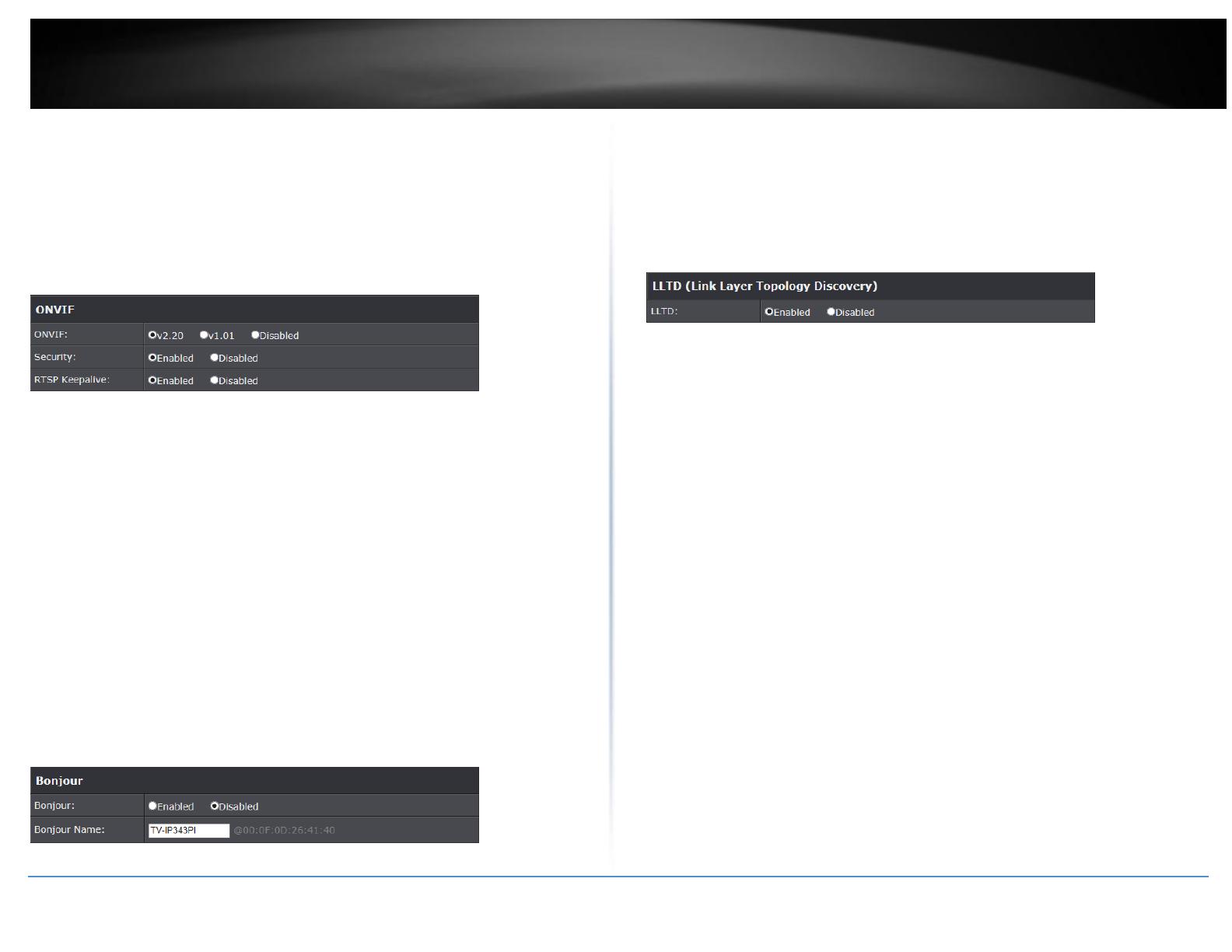
Network >> Network Setting >> ONVIF
Under ONVIF connection, the video will be transmitted by RTSP. Be sure to enable the
RTSP server in IP setting, or you're not able to receive the video via ONVIF.
ONVIF:
Choose your ONVIF version. The two devices that use ONVIF to communicate
should be set to the same version.
Security:
Select "Disable", then the username and password are not required when
accessing the camera via ONVIF. Select "Enable", then username and password
are necessary.
RTSP Keepalive:
When the function is enabled, the camera checks once in a while if the user who
links to the camera via ONVIF still keeps connecting. If the connection had been
broken, the camera stops transmitting video to user.
Network >> Network Setting >> Bonjour
This function enable Safari browser's bookmark to link to this IP camera. The Bonjour
name is the name that display in the bookmark. Please note the Bonjour function on
Safari browser does not support https protocol. If you selected “https” mode, you will
see the camera appears on Safari’s bookmarks but will not be able to access the camera.
Network >> Network Setting >> LLTD
If your PC supports LLTD, enable this function then you can check the connection status,
properties, and device position(like IP address) of this IP Camera in the network map. In
Windows Vista or Windows 7, you can find LLTD through the path: Call out the Control
Panel → Network and Internet → Network and Sharing Center → Click "See full map".
Network >> Advanced >> HTTPS
When the users access cameras via Https protocol, the transmitted information will be
encrypted so that the security level is arisen.
You can select the connection type.
Http: user can access the camera via Http path.
Https: user can access the camera via Https path but cannot via Http path.
Http & Https: Both the Http and Https path can be used to access the camera.
When you change the setting of connection type, it may cause connection error or
disconnection error if you switch the protocol directly. Therefore, Http & Https
mode is necessary. If you want to change from Http to Https, please switch to “Http
& Https” mode first, and then switch to “Https” mode. Same method when you
change from Https to Http.
The Https protocol has certificate verifying mechanism. When the user access a website
via Https, the browser will check the certificate of that domain and verify its trustiness
and secure.
© Copyright 2014 TRENDnet. All Rights Reserved.
16
TRENDnet User’s Guide
TV-IP343PI
Certificate generation process:
1.
Remove the existing certificate: Before you generate a new certificate, please
remove existing one. Select "Http" connection type and click "Remove". If a dialog
box pops up to ask you to confirm, click “Yes”.
2.
Created Request: Fill in the following form and click “apply”.
3.
After you generate a certificate request, if you choose to turn it to the trusted third-
party to verify, please click “Content” and copy all the request content.
4.
According to the certificate source, there are two ways to install the certificate.
If you had sent the certificate request to do sign and received a signed
certificate, please click” browse” and find the certificate file in your computer.
Click “Apply” to install it.
If you choose to generate a self-signed certificate, fill in the following forms and
set validity day, click “Apply” to finish installed it.
After finishing installation, you can click “Content” to call out and check the
certificate content.
© Copyright 2014 TRENDnet. All Rights Reserved.
17
TRENDnet User’s Guide
TV-IP343PI
5.
To use Https to access camera, open your browser, and key in "https://(IP
address)/" in the address bar. Now your data will be transmitted via encrypted
communications, and the browser will check your certificate status. If it shows you
a warning message. The warning message meant that the certificate is self-signed
or signed by distrusted institution. Click Continue to this website to view the view
the camera.
Network >> Advanced >> SNMP
SNMP (Simple Network Management Protocol) provides a simple framework for
administering networked hardware. To manage the IP camera, you have to prepare a
MIB browser or similar tools first. SNMPv1, SNMPv2c, and SNMPv3 can be enabled
simultaneously.
The following examples are based on MG- SOFT MIB Browser. Depending on your MIS
Browser, you may see different interface and options. Please refer to the user manual of
your MIB Browser.
SNMPv1 and SNMPv2:
The term "Community name" in SNMPv1 and SNMPv2c can be roughly regarded as
key. The person who has the community name has the authority to read or edit the
information of IP camera via SNMP.
Click the box to enable SNMPv1 or SNMPv2c protocol, and specify the community
name for write (read and write) and read (read-only). The user who use read
community name to access the IP camera cannot modify any data of the camera.
The community name can be any English characters and numbers, and must be
shorter than 31 bits.
SNMPv3:
For data security reason, the authentication and encryption assurances are added
when developing SNMPv3. The user has to give not only the security name (similar
with "community name" in v1&v2c) but the password in order to access the IP
camera. Please set security name, authentication type, authentication password,
encryption type, encryption password of write and read respectively. The security
© Copyright 2014 TRENDnet. All Rights Reserved.
18
TRENDnet User’s Guide
TV-IP343PI
name can be any English characters and numbers, and must be shorter than 31
letters. The password must be 8~64 letters in length.
Different from in SNMPv1 and v2c, the user have to create an account when using
SNMPv3. In the account parameters, key in the security name and password you
set in the camera to get accessing.
SNMPv1/SNMPv2 Trap:
Trap is a mechanism that allows a managed device to send messages to the
manager instead of waiting passively for polling from the manager. Specify the trap
event. When those events occur, the camera will send the ring message to the Trap
Address, which is usually the manager's IP address. Trap Community means the
community that can receive the trap message.
Note: Trap Address must be under the same LAN with IP camera.
Cold Start: The camera starts up or reboots.
Setting changed: The SNMP setting is changed.
Network Disconnected: The network connection was broken down. (The
camera will send trap messages after the network being connected again)
V3 Authentication Failed: A SNMPv3 user account tries to get authentication
but failed. (Due to incorrect password or community)
Network >> Advanced >> IP Address Filter
You can allow or
deny an IP address or even a range of the IP address to access the IP camera. If you
would like to deny a range of IP address but would allow an IP within that range can
access the camera, please setup the allow IP address in the 1
st
priority and set the deny
range of IP address as 2
nd
priority as example below.
  • Page 1 1
  • Page 2 2
  • Page 3 3
  • Page 4 4
  • Page 5 5
  • Page 6 6
  • Page 7 7
  • Page 8 8
  • Page 9 9
  • Page 10 10
  • Page 11 11
  • Page 12 12
  • Page 13 13
  • Page 14 14
  • Page 15 15
  • Page 16 16
  • Page 17 17
  • Page 18 18
  • Page 19 19
  • Page 20 20
  • Page 21 21
  • Page 22 22
  • Page 23 23
  • Page 24 24
  • Page 25 25
  • Page 26 26
  • Page 27 27
  • Page 28 28
  • Page 29 29
  • Page 30 30
  • Page 31 31
  • Page 32 32
  • Page 33 33
  • Page 34 34
  • Page 35 35
  • Page 36 36
  • Page 37 37
  • Page 38 38
  • Page 39 39
  • Page 40 40

Trendnet RB-TV-IP343PI User guide

Category
Security cameras
Type
User guide
This manual is also suitable for

Ask a question and I''ll find the answer in the document

Finding information in a document is now easier with AI