
(English)
DM-BR0003-09
Dealer's Manual
Dual Pivot Caliper Brake/
DUAL CONTROL LEVER
BR-9000
BR-9010
BR-6800
BR-6810
BR-5800
BR-5810
BR-RS500
BR-5710
BC-9000
BC-R680
SM-CB90

2
CONTENTS
IMPORTANT NOTICE .............................................................................................. 3
TO ENSURE SAFETY ............................................................................................... 4
INSTALLATION ....................................................................................................... 7
Installation to the handlebar ......................................................................................................................7
Installation of the brake cable ...................................................................................................................8
Installing SM-CB90 .....................................................................................................................................11
Installation of the brake caliper ................................................................................................................ 12
Brake shoe setting position .......................................................................................................................21
Fixing the BC-9000/R680 cable ..................................................................................................................22
ADJUSTMENT ...................................................................................................... 26
Arch spring tension adjustment ................................................................................................................26
Readjustment of the shoe clearance (In the case the brake shoes are worn) ........................................ 27
MAINTENANCE .................................................................................................... 30
Replacement of the cartridge shoe ...........................................................................................................30
Brake shoe characteristics ......................................................................................................................... 32

3
IMPORTANT NOTICE
•
This dealer’s manual is intended primarily for use by professional bicycle mechanics.
Users who are not professionally trained for bicycle assembly should not attempt to install the components themselves using the
dealer’s manuals.
If any part of the information on the manual is unclear to you, do not proceed with the installation. Instead, contact your place
of purchase or a local bicycle dealer for their assistance.
•
Make sure to read all instruction manuals included with the product.
•
Do not disassemble or modify the product other than as stated in the information contained in this dealer’s manual.
•
All dealer’s manuals and instruction manuals can be viewed on-line on our website (http://si.shimano.com).
•
Please observe the appropriate rules and regulations of the country, state or region in which you conduct your business as a
dealer.
For safety, be sure to read this dealer’s manual thoroughly before use, and follow it for correct use.
The following instructions must be observed at all times in order to prevent personal injury and physical damage to
equipment and surroundings.
The instructions are classified according to the degree of danger or damage which may occur if the product is used
incorrectly.
DANGER
Failure to follow the instructions will result in death or serious injury.
WARNING
Failure to follow the instructions could result in death or serious injury.
CAUTION
Failure to follow the instructions could cause personal injury or physical damage to equipment and surroundings.

4
TO ENSURE SAFETY
WARNING
•
When installing components, be sure to follow the instructions that are given in the instruction manuals.
It is recommended that you use only genuine Shimano parts. If parts such as bolts and nuts become loose or damaged, the bicycle
may suddenly fall over, which may cause serious injury.
In addition, if adjustments are not carried out correctly, problems may occur, and the bicycle may suddenly fall over, which may
cause serious injury.
•
Be sure to wear safety glasses or goggles to protect your eyes while performing maintenance tasks such as replacing parts.
•
After reading the dealer's manual thoroughly, keep it in a safe place for later reference.
Be sure to also inform users of the following:
•
It is important to completely understand the operation of your bicycle’s brake system. Improper use of your bicycle’s brake
system may result in a loss of control or a fall, which could lead to severe injury.
Because each bicycle may handle differently, be sure to learn the proper braking technique (including brake lever pressure and
bicycle control characteristics) and operation of your bicycle.
This can be done by consulting your professional bicycle dealer and the bicycle’s owners manual, and by practicing your riding
and braking technique.
•
If the front brake is applied too strongly, the wheel may lock and the bicycle may fall forward, and serious injury may result.
•
Always make sure that the front and rear brakes are working correctly before you ride the bicycle.
•
The required braking distance will be longer during wet weather. Reduce your speed and apply the brakes early and gently.
•
If the road surface is wet, the tires will skid more easily. If the tires skid, you may fall off the bicycle. To avoid this, reduce your
speed and apply the brakes early and gently.
•
Be careful not to allow any oil or grease to get onto the brake shoes. If any oil or grease does get on the shoes, contact the
place of purchase or a bicycle dealer, otherwise the brakes may not work correctly.
•
Check the brake cable for rust, fraying, and cracks, and contact the place of purchase or a bicycle dealer if any such problems
are found. If this is not done, the brakes may not work correctly.
•
Because of the characteristics of the carbon fiber material, you must never modify the levers, otherwise the lever may break
and the brakes may no longer work as a result.
•
Check before riding that there is no damage such as carbon separation or cracking. If there is any damage, stop using the
bicycle and contact the place of purchase or a bicycle dealer. Otherwise, the lever may break, and braking may become
disabled.

5
For Installation to the Bicycle, and Maintenance:
•
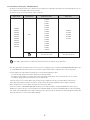
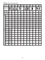
For brake use the dual control lever or brake lever according to the combination specified in the following table. Do not use
the combinations with "NO!" indication in the table.
The brakes may be excessively effective, and you may fall.
Caliper brake Combinations Dual Control Lever Brake lever
BR-9000
BR-9010
BR-7900
BR-6800
BR-6810
BR-5800
BR-5810
BR-RS500
BR-5710
BR-5700
OK
ST-9070
ST-9071
ST-9001
ST-9000
ST-6870
ST-6871
ST-6800
ST-6770
ST-5800
ST-5700
ST-4600
ST-3500
ST-2400
ST-R460
ST-R353
ST-R350
BL-4600
BL-3500
BL-R780
BL-2400
BL-TT79
Dual control lever for road bikes
other than the above
Brake lever for road bikes
other than the above
: The “NO!” symbols indicate combinations that should not be used under any circumstances.
•
The cable adjustment nut and the quick release lever are not equipped on the rear brake of BR-9010/6810/5810/5710; be sure
to use SM-CB90. When the brake shoes are worn down, it becomes impossible to adjust the shoe clearance by hand.
•
Securely tighten the caliper brake mounting nuts to the specified tightening torque.
·
Use lock nuts with nylon inserts (self-locking nuts) for nut-type brakes.
·
For sunken nut type brakes, use sunken nuts of the appropriate length which can be turned six times or more; when
re-installing, apply sealant (locking adhesive) to the nut threads.
If the nuts become loose and the brakes fall off, they may get caught up in the bicycle and the bicycle may fall over.
Particularly if this happens with the front wheel, the bicycle may be thrown forward and serious injury could result.
•
Brakes designed for use as rear brakes should not be used as front brakes.
•
For the shoe holder of BR-9010/6810/5810/5710, always use the dedicated brake shoe (R55C4, R55C4 (for carbon rim), or
R55C4-1 (for carbon rim)). The conventional brake shoes (R55C3, R55C3 (for carbon rim), R55C2, R55C (for carbon rim), R55C
(for ceramic rim), and R55C+1) have a different fixing position. This prevents the fixing bolt from being tightened, which will
cause the brake shoe to come off and disable braking.

6
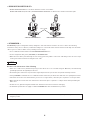
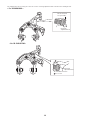
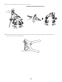
< BR-9010-RS/6810-RS/5810-RS >
•
BR-9010-RS/6810-RS/5810-RS is a rear brake. Cannot be used as a front brake.
BR-9010-F/6810-F/5810-F (front brake) and BR-9010-RS/6810-RS/5810-RS use different shoe holders and internal parts.
Shoe holder
< BR-9010-F/6810-F/5810-F > < BR-9010-RS/6810-RS/5810-RS >
< BC-9000/R680 >
BC-9000/R680 (polymer coating brake cable) is designed to have low frictional resistance. Be sure to observe the following
instructions. If they are not observed, a sufficient holding force of the brake cable cannot be delivered. This may cause the brake
cable to get loose and lose brake control, resulting in severe injury.
•
Use in combination with a brake in the BR-9000/6800/5800/RS500 series.
•
Use the designated cable grease (Y04180000) for BC-9000/BC-R680.
•
When the inner cable is passed through an outer casing, grease may adhere on the inner cable fixing section. Be sure to wipe
off the grease with a cloth before fixing the inner cable.
NOTICE
Be sure to also inform users of the following:
•
In the case of carbon levers, wash them by using a soft cloth. Be sure to use a neutral detergent. Otherwise, the material may
get damaged, and the strength may be affected.
•
Avoid leaving the carbon levers in places where high temperatures are present. Also keep them well away from fire.
•
If using SHIMANO's road brake shoes in combination with ceramic rims, the brake shoes will wear more quickly than normal.
•
If the brake shoes have worn down until the grooves are no longer visible, contact the place of purchase or a bicycle dealer.
•
Different brake shoes have their own characteristics. Contact the place of purchase or a bicycle dealer when purchasing the
brake shoes.
•
Products are not guaranteed against natural wear and deterioration from normal use and aging.
•
For maximum performance we highly recommend SHIMANO lubricants and maintenance products.
The actual product may differ from the illustration because this manual is intended chiefly to explain the procedures for
using the product.

7
INSTALLATION
List of tools to be used
The following tools are needed to assemble this product.
Brake caliper
Usage location Tool
Brake-fixing bolt
5 mm hexagon wrench (BR-9000/6800/5800/RS500)
4 mm hexagon wrench (BR-9010/6810/5810/5710)
Shoe fixing bolt 4 mm hexagon wrench
Cable fixing bolt 5 mm hexagon wrench
Centering adjustment bolt
3 mm hexagon wrench (BR-9000/6800/5800/RS500)
2 mm hexagon wrench (BR-9010/6810/5810/5710)
Spring adjustment bolt 2 mm hexagon wrench (BR-9000/9010*/6800)
* BR-9010 consists of F and R models only.
(Spring adjustment cannot be carried out for BR-9010-RS.)
Brake cable
Usage location Tool
Cable cutter TL-CT12
Dual control lever
Usage location Tool
Clamp bolt 5 mm hexagon wrench
When installing the components to carbon frame/handle bar surfaces, verify with the manufacturer of the carbon frame/parts for
their recommendation on tightening torque in order to prevent over tightening that can cause damage to the carbon material and/
or under tightening that can cause lack of fixing strength for the components.
ST-9000/6800/5800/5700
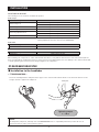
Installation to the handlebar
< ST-9000/6800/5800 >
•
Secure the assembly with the clamp bolt at the upper section of the bracket. Pull the bracket cover back side and use a 5 mm
hexagon wrench to tighten the clamp bolt.
Tightening torque:
6 - 8 N·m
Clamp bolt
Notice:
The clamp band, clamp bolt, and clamp nut of ST-9000/6800/5800 have no compatibility with other products. Do not use
components that are used in other products together.

8
< ST-5700 >
Move the bracket cover forward, and then securely tightening the mounting nut with a 5 mm hexagon wrench.
Tightening torque:
6 - 8 N·m
5 mm
hexagon wrench
Hollow
Bracket cover
The correct way for
clamp washer (B) to
face is so that the
small hollow on the
surface is in the
top-left corner.
Installation of the brake cable
A lubricant appropriate for this product is used for the brake cable and it is shipped in a properly lubricated state.
WARNING
When passing the inner cable through an outer casing, if grease adheres on the inner cable fixing section, wipe it off with a cloth
before fixing the inner cable. If grease adheres on the fixing section, a sufficient holding force of the brake cable cannot be
delivered. This may cause the brake cable to get loose and lose brake control, resulting in severe injury.
Notice:
Be careful not let the BC-9000/R680 inner cable come into contact with the shifting lever or the metal section (adjustment section)
of the caliper brake. When the inner cable is installed, coating may be damaged and become fluffy; however, it will not affect the
function.
Use a cable which still has some length to spare even when the handlebars are turned all the way to both sides.
Cable used
< ST-9000/6800/5800 >
BC-9000/BC-R680 Inner cable Outer casing
ɸ 1.6 mm
ɸ 5 mm
< ST-5700 >
BC-1051 Inner cable
SLR outer casing
ɸ 1.6 mm
ɸ 5 mm

9
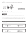
Cutting the outer casing
Notice:
•
Use a cable which still has some length to spare even when the handlebars are turned all the way to both sides.
•
Be careful not to get your hand injured by the TL-CT12 needle section.
1.
Use the cable cutter (TL-CT12) or an equivalent tool to cut the cable so that the coil does not tip over inward.
Good example
Coil not tipping
over inward
Bad example
Coil tipping over
inward
TL-CT12
2.
After cutting, expand the tip of the liner (ɸ 2.2 or more) with TL-CT12 or other narrow tool.
TL-CT12
Arranging the cut surface
into a perfect circle
TL-CT12 needle
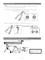
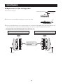
Rear brake cable/Outer cap with tongue installation position
•
Install the outer cap with tongue at the position (
A
,
B
/
A
,
B
) specified in the illustration.
BR-9000 / 6800 / 5800 / RS500 / 9010-RS / 6810-RS
BR-9010 / 6810 / 5810 / 5710
B
B
A
A
Notice:
If using the inner cable BC-1051, use
ordinary outer caps not outer caps
with tongue.

10
< ST-9000/6800/5800 >
Move the lever in the direction of brake operation and put the brake cable through.
Cable hook
Outer casing
Inner end
Make sure that the inner end is firmly
seated in the cable hook.
Cable hook
Inner end
< ST-5700 >
Pass the inner cable through as shown in the illustration, and then set the inner cable drum into the cable hook.
Name plate
Outer casing
Cable hook
Inner cable drum

11
Temporarily secure the outer casing to the handlebar (by using tape or
similar material).
Tape
Outer casing
WARNING
The cable adjustment nut and the quick release lever are not equipped on the rear brake of BR-9010/6810/5810/5710; be sure to use
SM-CB90 (Cable adjuster). When the brake shoes are worn down, it becomes impossible to adjust the shoe clearance by hand.
Installing SM-CB90
Install at the position specified in the illustration.
2
3
4
1
Outer insertion
opening on the
brake side
Cable adjustment
barrel
Inner cable
Outer casing
(BL side)
Lock nut
Outer casing (BR side)
OPEN
CLOSE
Notice:
Do not install where it is entangled with the top tube when the handle is turned.
Wrong setting

12
BR-9000/6800/5800/RS500/9010/6810/5810/5710
Installation of the brake caliper
< BR-9000/6800/5800/RS500 >
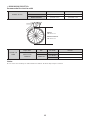
Recommended tire size/rim width
Available tire size
Thickness Outside tire diameter
BR-9000/6800 ɸ 25 mm or less ɸ 680 mm or less
BR-5800/RS500 ɸ 28 mm or less ɸ 684 mm or less
BR-9000/6800
680 mm or less
BR-5800/RS500
684 mm or less

13
Available rim
width
Caliper brake Rim Rim width Remarks
BR-9000/6800/5800/RS500
Aluminum rim 19.6 - 24 mm
Carbon rim
19.6 - 24 mm
24 - 28 mm Please use R55C4-1 (for carbon rims)
Notice:
When using a carbon rim with a width of 24 to 28 mm use the R55C4-1 (for carbon rims).
The front brake cannot be installed as the rear brake and vice versa.
Compress the arch‚ and set while the shoe is in firm contact with the rim.
Centering
adjustment bolt
Notice:
If the brake arm touches the frame
when the handlebar is turned, attach
the frame protection sticker which is
included to the frame.
Tightening torque:
8 - 10 N·m
5 mm hexagon wrench

14
The adjustment position serving as a reference for the centering adjustment bolt is shown in the drawing below.
< For BR-9000/6800 >
The bolts must
not protrude.
Centering
adjustment bolt
<For BR-5800/RS500>
A
The standard interval of
A
is 2 - 3 mm.
Centering
adjustment bolt

15
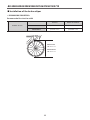
< BR-9010/6810/5810/5710 >
Recommended tire size/rim width
Available tire size
Thickness Outside tire diameter
BR-9010 ɸ 25 mm or less ɸ 680 mm or less
BR-6810/5810/5710 ɸ 28 mm or less ɸ 684 mm or less
BR-9010
680 mm or less
BR-6810/5810/5710
684 mm or less
Available rim
width
Caliper brake Rim Rim width Remarks
BR-9010/6810/
5810/5710
Aluminum rim 21 - 24 mm
Carbon rim
21 - 24 mm
24 - 28 mm Please use R55C4-1 (for carbon rims)
Notice:
Do not remove the assembly tool until installation is finished. The brake caliper may be scratched.

16
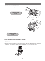
Front
1.
Temporarily fix the assembly tool together on the frame base.
Tightening torque:
0.5 N·m
1
4 mm
hexagon wrench
2, 3.
Pull out the assembly tool in the direction of the arrow.
2
3
4.
Fully tighten the brake fixing bolt.
Tightening torque:
5 - 7 N·m
5.
Finally, remove the protection sheet.

17
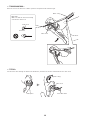
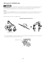
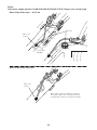
Rear
< BR-9000/6800/5800/RS500/9010/6810 >
1.
Temporarily fix the assembly tool together on the frame
base.
4 mm
hexagon wrench
Brake fixing bolt
Tightening torque:
0.5 N·m
2.
Pull out the assembly tool in the direction of the arrow.
2
3.
Fully tighten the brake fixing bolt.
Tightening torque:
5 -7 N·m
4.
Finally, remove the protection sheet.
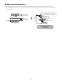
Caution when attaching the caliper brake to the frame:
< BR-9010/6810 >
•
There are 2 types of brake-fixing bolt with lengths of 9.2 mm and 7.5 mm. When attaching the caliper brake
to the frame, select a bolt with a length that matches the depth of the screw hole in the frame.
Brake-fixing bolt

18
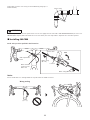
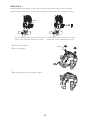
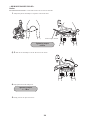
< BR-5810/5710 >
•
When mounting the caliper brake on a frame with a screw hole 9.2 mm deep or deeper, remove the adapter.
•
When mounting the caliper brake on a frame with a screw hole less than 9.2 mm deep, the adapter is required.
For frames with a screw hole 9.2 mm deep or deeper
(Frames such as frames with aluminum screws)
For frames with a screw hole less than 9.2 mm deep
(Frames such as frames with stainless steel screws)
Adapter
1.
Remove the assembly tool.
1
2
Adapter
2.
Remove the adapter.
3.
Mount the assembly tool in the original condition.
3

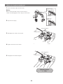
19
4.
Temporarily fix the assembly tool together on the frame
base.
4 mm
hexagon wrench
Brake fixing bolt
Tightening torque:
0.5 N·m
5.
Pull out the assembly tool in the direction of the arrow.
5
6.
Fully tighten the brake fixing bolt.
Tightening torque:
5 - 7 N·m
7.
Finally, remove the protection sheet.

20
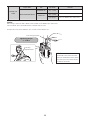
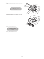
< BR-9010-RS/6810-RS/5810-RS >
Notice:
BR-9010-RS/6810-RS/5810-RS is a rear brake. Cannot be used as a front brake.
1.
Temporarily fix the assembly tool together on the frame base.
Tightening torque:
0.5 N·m
1
4 mm hexagon wrench
2, 3.
Pull out the assembly tool in the direction of the arrow.
2
3
4.
Fully tighten the brake fixing bolt.
Tightening torque:
5 - 7 N·m
5.
Finally, remove the protection sheet.
Page is loading ...
Page is loading ...
Page is loading ...
Page is loading ...
Page is loading ...
Page is loading ...
Page is loading ...
Page is loading ...
Page is loading ...
Page is loading ...
Page is loading ...
Page is loading ...
Page is loading ...
-
 1
1
-
 2
2
-
 3
3
-
 4
4
-
 5
5
-
 6
6
-
 7
7
-
 8
8
-
 9
9
-
 10
10
-
 11
11
-
 12
12
-
 13
13
-
 14
14
-
 15
15
-
 16
16
-
 17
17
-
 18
18
-
 19
19
-
 20
20
-
 21
21
-
 22
22
-
 23
23
-
 24
24
-
 25
25
-
 26
26
-
 27
27
-
 28
28
-
 29
29
-
 30
30
-
 31
31
-
 32
32
-
 33
33


Ask a question and I''ll find the answer in the document
Finding information in a document is now easier with AI
Related papers
-
Shimano BR-7403 Service Instructions
-
-
-
-
-
-
-
-
Shimano BR-M550 Service Instructions
-
Other documents
-
 Elicto Everybot RS500 User manual
-
Bontrager 2013 Trek Madone 7 series brake User manual
-
AME 72080 Owner's manual
-
Autonics SFDL-SDK Series Quick start guide
-
Trane PTEC0901GCA User manual
-
Hitachi ZAXIS 120-3 class User manual
-
Chariot Carriers Cavalier User manual
-
-
Diamondback SHEPPARD CYCLES Owner's manual
-
 Stitch KM2002-1-JV Operating instructions

