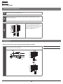
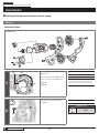
Shimano RD-M9000 is a high-performance rear derailleur designed for mountain biking. It features Shadow RD+ technology for improved chain stability and reduced chain slap, making it ideal for aggressive riding on rough terrain. With a total capacity of 45T, the RD-M9000 can handle a wide range of gear combinations, providing precise and reliable shifting even under load.
Shimano RD-M9000 is a high-performance rear derailleur designed for mountain biking. It features Shadow RD+ technology for improved chain stability and reduced chain slap, making it ideal for aggressive riding on rough terrain. With a total capacity of 45T, the RD-M9000 can handle a wide range of gear combinations, providing precise and reliable shifting even under load.


-
 1
1
-
 2
2
-
 3
3
-
 4
4
-
 5
5
-
 6
6
-
 7
7
-
 8
8
-
 9
9
-
 10
10
-
 11
11
-
 12
12
-
 13
13
-
 14
14
-
 15
15
-
 16
16
-
 17
17
-
 18
18
-
 19
19
-
 20
20
-
 21
21
-
 22
22
-
 23
23
-
 24
24
-
 25
25
-
 26
26
-
 27
27
-
 28
28
-
 29
29
-
 30
30


Shimano RD-M9000 Dealer's Manual
- Type
- Dealer's Manual
- This manual is also suitable for
Shimano RD-M9000 is a high-performance rear derailleur designed for mountain biking. It features Shadow RD+ technology for improved chain stability and reduced chain slap, making it ideal for aggressive riding on rough terrain. With a total capacity of 45T, the RD-M9000 can handle a wide range of gear combinations, providing precise and reliable shifting even under load.
Ask a question and I''ll find the answer in the document
Finding information in a document is now easier with AI
Related papers
-
Shimano RD-M280 Dealer's Manual
-
Shimano FD-AX60 Exploded View
-
Shimano RD-RX800 Dealer's Manual
-
Shimano FD-M3120 Dealer's Manual
-
Shimano FD-M676 Dealer's Manual
-
Shimano SL-M3100 Dealer's Manual
-
Shimano FD-T6000 Dealer's Manual
-
Shimano SL-RS700 Dealer's Manual
-
Shimano FD-M9020 Dealer's Manual
-
Shimano FD-RX400 Dealer's Manual