Type UTCG, UCCG, UCDG
INSTRUCTIONS
English
T
he thermostat is an electronic on/off
thermostat for control of temperature by means
o
f an NTC sensor either placed externally or
i
nternally in the thermostat. The thermostat has
i
ntegrated a Ground Fault Circuit Interrupter
(GFCI).
T
he thermostat is suitable for 50/60 Hz supply.
T
he thermostat is for flush mounting in a wall
socket.
P
roduct program
T
hermostats with built-in GFCI Voltage
U
TCG-9991 Incl. floor sensor 3 m (10ft) 120V
U
TCG-9999 With built-in room sensor 120/240V
Clock-thermostats with built-in GFCI
UCCG-9991 Incl. floor sensor 3m (10ft) 120V
U
CCG-9999 With built-in room sensor 120/240V
UCDG-9999 With 2 sensors; 120V
built-in room sensor and
i
ncl. floor sensor 3m (10ft)
Mounting of floor sensor (fig. 3)
The floor sensor is used for temperature
regulation in floor surfaces. For easy
replacement the sensor can be mounted in a
tube which is placed between 2 heating cables.
The tube is ended towards the floor surface and
sealed.
If required, the sensor cable can be extended
up to about 100 m with a standard installation
cable. 2 leads in a multi lead cable, which is
used as supply cable for the heating cable,
must not be used.
Mounting of thermostat with built-in sensor
(fig. 4)
The room sensor is used for comfort temperature
regulation in rooms. The thermostat is mounted
on the wall with free air circulation about 1.6 m
above the floor. Draught, direct sunlight, or any
other direct heating outlet
must be avoided. No external sensor is to be
connected.
Mounting of thermostat
Installation
TURN OFF THE POWER TO THE HEATING
SYSTEM AT THE MAIN POWER PANEL TO
AVOID ELECTRICAL SHOCK.
KEEP AIR VENTS OF THE THERMOSTAT
CLEAN AND OBSTRUCTION FREE.
This thermostat is an electrical product and
must be installed in conformity with the National
and/or Local Electrical Code. The installation
must be performed by qualified personnel
where required by law. The thermostat is
equipped with a ground fault circuit interrupter
(GFCI), which require that the line and load is
isolated from each other for correct operation.
The resistive load must not exceed 15A (1800W
at 120Vac /3600W at 240Vac).
During a ground fault, the two lines will be cut-
off.
INSTALLATION AT 120VAC APPLICATION:
NEUTRAL CABLE (NORMAL WHITE) MUST BE
CONNECT TO THERMOSTATS TERMINAL L2
(N). FAILURE TO DO SO COULD CAUSE
SERIOUS BODILY INJURY OR DEATH.
Line Cable
Delivers power from the service panel (breaker
p
anel or fuse box) to the thermostat.
T
his cable shall only be connected to the
thermostat’s line terminals marked L1(L) and L2
(
N).
L
oad Cable
Delivers power from the thermostat to the
h
eating cable.
T
his cable shall only be connected to the
thermostat’s load terminals marked load, 15A.
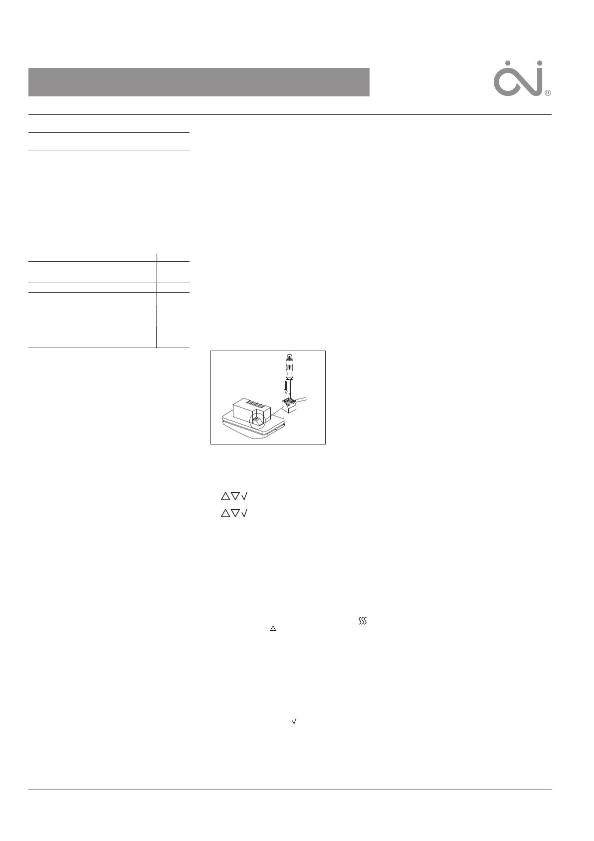
1
. Use a screwdriver to open the lock (fig. 1),
a
nd remove the frame
2. Connect cables according to the diagram
(fig. 2)
3
. The thermostat is mounted in the wall socket.
T
he frame are remounted.
T
emperature sensor
T
he floor sensor is connected to the screw less
terminals marked sensor. Push with a
s
crewdriver on the terminal spring and mount
the wires.
Operation
With integrated clock, type UCCG and UCDG:
The first time the thermostat is connected,
time and day must be set:
Setting of time (the clock flashes
during setting)
Setting of day (day flashes during
setting)
Without integrated clock, type UTCG:
Actual temperature setting is shown and the
thermostat is ready for use.
Checking GFCI
It is important that the GFCI has been checked
for correct installation and function.
To check the GFCI:
Testing can only be performed if the thermostat
has a heating demand
Adjust the set point until the heating symbol ( )
appears, use the ( ), to increase the heating
demand. Wait 10 sec to let the thermostat work
according to the new set point.
Press the button "TEST"
The test is conclusive if the red light on the
thermostat lightens, and the display signs
disappear. If this does not occur, check the
installation.
Press on RESET button to reset the GFCI.
The red light should disappear and the display
will return to normal appearance.
Push ok accept button ( ) to cancel the
previously set temperature
If the test fails, check your heating cable and
the thermostat.
The GFCI test should be carried out monthly.
If the GFCI trips in normal operation, without
pressing the TEST button, there could be a
g
round fault! To check whether it is a ground
f
ault or a nuisance tripping, press RESET. If this
cause the red light to shot off and not comes on
a
gain, it was a nuisance tripping and the system
i
s functioning. If this cannot be done there is a
g
round fault!
Check your heating cable, the sensor cable and
t
he thermostat. Exchange the defective part.
Programming
See user’s manual.
F
ault location
If the sensor is disconnected or short-circuited,
the heating system is cut out. The sensor can
b
e checked according to the resistance table
f
ig. 5.
E
rror codes
E
0: Internal error. The thermostat must be
replaced.
E
1: Built-in sensor short-circuited or
disconnected. The thermostat must be
replaced
E
2: External sensor short-circuited or
disconnected.
C-UL LISTED
According to the following standards,
GFCI: UL 943 4.th.
CSA C22.2 No.144.1-06
Thermostat: UL 873
CSA C22.2 No. 24
UL file number: E157297
Classification
The product is a class II device (enhanced
insulation) and the product must be connected
to the following leads:
Phase (L, L1) 120 V ±15%, 50/60 Hz
Neutral (N, L2)
Load max. 15A
The terminals are suitable for field wiring of 12
AWG to 22 AWG conductors
Technical Data
Supply . . . . . . . . . . . . . .120/240 Vac 50/60 Hz
Load . . . . . . . .15A maximum (resistive load)
Power . . . . . . . . . . . . . . . .1800 W at 120 Vac
. . . . . . . . . . . . . . . .3600 W at 240 Vac*
GFCI . . . . . . . . . . . . . . . . . . . .5 mA trip level
Temperature range .+5 to +40°C, +40 to +104˚F
Amb. Temperature range
Thermostat . . . . . . . .0 to +40°C, +32 to +104˚F
GFCI . . . . . . . . .-35 to +65°C, -31 to +149˚F
*)
Only type UTCG-9999 and UCCG-9999.
5
7609C - 08/09 (DJU)
© 2009 OJ Electronics A/S - ® The OJ trademark is a registred trademark belonging to OJ Electronics A/S


