Dell Servers Solution Resources Owner's manual
- Category
- Security device components
- Type
- Owner's manual
This manual is also suitable for

1 Memory Errors and Dell PowerEdge YX4X Server Memory RAS Features
Whitepaper
Memory Errors and Dell EMC PowerEdge
YX4X Server Memory RAS Features
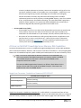
Introduction
Memory sub-system errors are some of the most common types of errors seen on modern computing
systems. Understanding how memory errors occur and how to prevent or avoid them can be a complex
subject – one that has challenged countless numbers of industry researchers and developers over the
last 30 years. While Dell EMC PowerEdge servers are designed to provide industry leading Reliability,
Availability, and Serviceability (RAS) on memory issues, we realize that many of our technically savvy
customers may want to know more on what’s happening ‘under the hood’ of their servers. This
technical whitepaper is divided in four sections to help PowerEdge users to understand about the
following memory error topics:
• Types of memory errors and how they may affect a server
• Dell EMC PowerEdge YX4X server memory RAS capabilities
• Configuring a PowerEdge server to achieve maximum memory up-time
• Recommended user actions when encountering memory errors
Important: The content covered in this whitepaper applies to Dell EMC PowerEdge
YX4X servers. The features described in this document assumes the user is running
the latest versions of Dell EMC PowerEdge server firmware, such as BIOS and
iDRAC. (For example, self-healing is not available on versions of BIOS earlier than
2.x.x.)
Revision: 1.0
Issue Date: 1/3/2020
Issue Date: 1/3/2020

2 Memory Errors and Dell PowerEdge YX4X Server Memory RAS Features
Revisions
Date
Description
January 3, 2020
Initial release
Author
Name
Role
Jordan Chin
Memory Technologist, Distinguished Member Technical Staff, Dell EMC
Acknowledgements
This paper had contributions from the following people:
Name
Role
Stuart Berke
CPU and Memory Technologist, VP, Fellow, Dell EMC
David Chalfant
BIOS Development, Technical Staff, Dell EMC
Huong Nguyen
BIOS Development, Technical Staff, Dell EMC
Ching-Lung Chao
BIOS Development, Technical Staff, Dell EMC
Fred Spreeuwers
IPS Engineering, Technical Staff, Dell EMC
Mark Dykstra
IPS Engineering, Senior Principal Engineer, Dell EMC
Rene Franco
Memory Systems Engineering, Senior Manager, Dell EMC
Mark Farley
Component Quality Engineering, Senior Principal Engineer, Dell EMC

3 Memory Errors and Dell PowerEdge YX4X Server Memory RAS Features
A Primer on Memory Errors
To fully understand the memory RAS response capabilities of PowerEdge servers, it is first helpful to
have an understanding of the various types of possible memory errors.
DRAM issues can be broadly classified into two categories described below:
o Soft Errors
o Soft errors are transient in nature and may often be caused by electrical disturbances in
the memory sub-system components. These disturbances could occur in any one of
many locations within the memory subsystem including the processor memory
controller, processor-internal buses, processor cache, processor socket or connector,
motherboard bus traces, discrete memory buffer chips (if present), DIMM connectors,
or individual DRAM components on DIMMs.
o Soft errors may be caused by phenomena such as high-energy particle strikes in the
memory subsystem or electrical noise in the circuits. Single or multiple bits can be
affected, with single-bit errors corrected using demand or patrol scrubbing.
o Hard Errors
o Hard errors are persistent in nature and cannot be resolved over a period of time,
through system resets, or through system power-cycles. These types of errors could
occur as a result of stuck-at faults (i.e. degradation of a single lane on a bus or a single
memory cell in a DRAM component), due to failure of an entire device (for example
connector, processor, memory buffer, or DRAM components), due to improper bus
initialization, or memory power issues. Failures within a DRAM component may consist
of entire device failure, bank region failure within a device, pin failure, column, or cell
failure.
o Hard errors may be caused by physical part damage, Electrostatic Discharge (ESD),
electrical overcurrent conditions, over temperature conditions, or irregularities in
processor or DRAM fabrication or module assembly.
The two categories of DRAM errors previously described can ultimately lead to two types of memory
errors:
o Correctable Errors (CEs)
o Correctable errors are errors that can be detected and corrected by the server platform.
These are typically single-bit errors, though based on CPU and memory configuration,
may also be some types of multi-bit errors (corrected by Advanced ECC). Correctable
errors can be caused by both soft and hard errors and will not disrupt operation of
PowerEdge servers.
o As DRAM based memory shrinks in geometry to grow in capacity, an increasing number
of correctable errors are expected to occur as a natural part of uniform scaling.
Additionally, due to various other DRAM scaling factors (e.g. decreasing cell
capacitance) there is an expected increase in the number of error generating
phenomenon such as Variable Retention Time (VRT) [1] and Random Telegraph Noise
(RTN) [2].
o Within the server industry, it is an increasingly accepted understanding shared by Dell
that some correctable errors per DIMM is unavoidable and does not inherently warrant

4 Memory Errors and Dell PowerEdge YX4X Server Memory RAS Features
a memory module replacement. However, some server competitors will go as far as to
say that an indefinite number of correctable errors are acceptable – a belief that is not
shared by Dell Engineering. Instead, PowerEdge server firmware will intelligently
monitor the health of memory and recommend self-healing action or module
replacement based on a variety of factors including DIMM capacity, rates of correctable
errors, and effectiveness of available self-healing. The intent behind Dell’s proprietary
predictive failure algorithms is to proactively identify DIMMs that are most likely to
continue to degrade and potentially generate uncorrectable errors.
o Uncorrectable Errors (UCEs)
o Uncorrectable errors are errors that can be detected but could not be corrected by the
server platform. These are the result of multi-bit errors and may be caused by any
combination of soft and hard errors (for example, soft-soft, soft-hard, hard-hard, etc.).
o Occurrence of an uncorrectable error will typically lead to either an application crash
(non-fatal error) or server crash (fatal error) – both of which result in unexpected
downtime. Systems with MCA Recovery have the capability of performing run-time
recovery from some types of uncorrectable memory errors.
A Primer on Dell EMC PowerEdge Server Memory RAS Capabilities
Previously discussed memory errors are mitigated through PowerEdge server memory RAS capabilities
which entail fault avoidance, detection, and correction in hardware and software. These mitigating RAS
features are all intended to improve system reliability and extend uptime in the event of memory errors.
FYI: It is useful to understand the difference between x4 and x8 DIMMs. This
refers to the width of the DRAM components on a memory module. x4 DIMMs
utilize DRAM components that have a 4-bit width and x8 DIMMs utilize
components with an 8-bit width.
The common DIMM organizational notation is as follows: #RxN. Where # is the
number of ranks and N is the width of the DRAM. Example – 2Rx4 means the
DIMM has two ranks of x4 DRAM devices.
Single Error Correction - Double Error Detection (SEC-DED) ECC
SEC-DED Feature Support Table
Platforms Supported
Intel Platforms:
(All Xeon Families)
AMD Platforms:
(All EPYC Families)
DIMMs Supported
x4 DIMMs:
x8 DIMMs:
Single Error Correction - Double Error Detection ECC, or SEC-DED ECC, is the most basic form of error
correcting code (ECC) available. All PowerEdge servers (both Intel and AMD based platforms) configured
with ECC memory modules are capable of SEC-DED for each memory page access (64 data bits + 8 ECC

5 Memory Errors and Dell PowerEdge YX4X Server Memory RAS Features
bits). This means that any one bit among the 72-bits accessed from DRAM can be incorrect and
PowerEdge server hardware will automatically correct it – regardless of cause.
Advanced ECC
Advanced ECC Feature Support Table
Platforms Supported
Intel Platforms:
(Xeon SP Families Only)
AMD Platforms:
(All EPYC Families)
DIMMs Supported
x4 DIMMs:
(Use of x4 DIMMs May Provide DRAM Device Correction)
x8 DIMMs:
(Use of x8 DIMMs May Provide Nibble Correction)
Advanced ECC is a RAS feature that provides error correction on single-bit and multi-bit failures that are
bound within 4-bits (nibble) of memory accesses. When used in conjunction with DIMMs based on x4
DRAM devices, Advanced ECC may provide error correction to an entire single DRAM device. This type of
error correction that covers an entire DRAM device has been branded in various forms, most
popularized as Chipkill and Single Device Data Correction (SDDC). Advanced ECC is a highly complex
feature that is based on the concept of Single Symbol Correcting – Double Symbol Detecting (SSC-DSD)
Reed-Solomon error correcting and detection code [3]. At a high level, SSC-DSD works by breaking up
cache line accesses into ‘code words’ which in turn are made up of multi-bit symbols. The size of these
symbols can vary depending upon the processor architecture. But regardless if the symbol size is 4-bits
or 32-bits, as the SSC-DSD name implies, the coding is designed such that a single symbol may be
corrected for various combinations of bit errors. In many cases, depending on the SSC-DSD
implementation, all bits in a symbol could be corrected if they had errors. Studies have indicated that
error correcting codes based on SSC-DSD may provide up to 42x better fault correction and avoidance
than SEC-DED ECC alone [4].
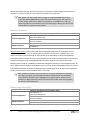
An example SSC-DSD coding implementation is represented in the following figures where a 64-byte
cache line is broken into eight code words (Figure 1). Each code word is made up of eighteen 8-bit
symbols and can be broken down into 128-bits of data and 16-bits of ECC (8-bits of CRC and 8-bits of
parity). The data and ECC is arranged (as shown by the various colors) such that all bits from an entire
symbol are located within a single x4 DRAM device. Depending on the SSC-DSD coding implementation,
Advanced ECC may correct various combinations of multiple bits error patterns within a single symbol
including the entire symbol itself (Figure 2). However, a pair of two single bit errors across two symbols
would yield an uncorrectable error (Figure 3).

6 Memory Errors and Dell PowerEdge YX4X Server Memory RAS Features
Cache Line
Code Word 0
1
. . .
32 4
5 76 8 9 1110 12 13 1514 16 65 6766 68
73 7574 76
78 8079 81 82 8483 85 86 8887 89 137 139138 140
69 7170 72
141 143142 144
Code Word 1
1
. . .
32 4
5 76 8 9 1110 12 13 1514 16 65 6766 68
73 7574 76
78 8079 81 82 8483 85 86 8887 89 137 139138 140
69 7170 72
141 143142 144
Code Word 2
1
. . .
32 4
5 76 8 9 1110 12 13 1514 16 65 6766 68
73 7574 76
78 8079 81 82 8483 85 86 8887 89 137 139138 140
69 7170 72
141 143142 144
Code Word 3
1
. . .
32 4
5 76 8 9 1110 12 13 1514 16 65 6766 68
73 7574 76
78 8079 81 82 8483 85 86 8887 89 137 139138 140
69 7170 72
141 143142 144
Code Word 4
1
. . .
32 4
5 76 8 9 1110 12 13 1514 16 65 6766 68
73 7574 76
78 8079 81 82 8483 85 86 8887 89 137 139138 140
69 7170 72
141 143142 144
Code Word 5
1
. . .
32 4
5 76 8 9 1110 12 13 1514 16 65 6766 68
73 7574 76
78 8079 81 82 8483 85 86 8887 89 137 139138 140
69 7170 72
141 143142 144
Code Word 6
1
. . .
32 4
5 76 8 9 1110 12 13 1514 16 65 6766 68
73 7574 76
78 8079 81 82 8483 85 86 8887 89 137 139138 140
69 7170 72
141 143142 144
Code Word 7
1
. . .
32 4
5 76 8 9 1110 12 13 1514 16 65 6766 68
73 7574 76
78 8079 81 82 8483 85 86 8887 89 137 139138 140
69 7170 72
141 143142 144
Figure 1 - Example Implementation of 8-Bit Symbol SIze Advanced ECC
1
. . .
32 4
5 76 8 9 1110 12 13 1514 16 65 6766 68
X
X
X
X
73 7574 76
78 8079 81 82 8483 85 86 8887 89 137 139138 140
X
X
X
X
69 7170 72
141 143142 144
Figure 2 - Advanced ECC can correct multi-bit errors in a single symbol…
1
. . .
32 4
5 76 8 9 1110 12 13 1514 16 65 6766 68
X
73 7574 76
78 8079 81 82 8483 85 86 8887 89 137 139138 140
X
69 7170 72
141 143142 144
Figure 3 - But Advanced ECC cannot correct errors in multiple symbols

7 Memory Errors and Dell PowerEdge YX4X Server Memory RAS Features
As described earlier, SSC-DSD implementations will vary based on CPU platform architecture and
generation. This results in different error correction coverage and memory configuration requirements
to enable Advanced ECC. The current SSC-DSD coding implementation in PowerEdge YX4X servers with
AMD EPYC 7xx1 processors will provide data correction on all error patterns within a single symbol. The
current SSC-DSD coding implementation in PowerEdge YX4X servers with Intel Xeon SP processors will
provide data correction on most of the possible error patterns within a single symbol. In PowerEdge
YX4X servers, Advanced ECC is now enabled by default as part of Independent Mode on all Intel Xeon SP
and AMD EPYC based platforms. PowerEdge YX4X servers with Intel Xeon E or lower tier processors do
not provide Advanced ECC capabilities.
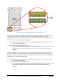
It was earlier mentioned that Advanced ECC, when used in conjunction with x4 DIMMs, may provide
error correction to a single DRAM device including failure of the entire device itself. This is achieved by
the processor organizing memory accesses such that a given DRAM device is only contributing data to a
single symbol – and through SSC-DSD, any one symbol can be fully redundant. On the other hand,
DIMMs with x8 DRAM devices will straddle two symbols and may only provide partial device correction
at the nibble level. An uncorrectable error will occur should both symbols within a x8 DRAM device
experience an error or the entire device fail.
1
. . .
32 4
5 76 8 9 1110 12 13 1514 16 65 6766 68
X
X
X
X
73 7574 76
78 8079 81 82 8483 85 86 8887 89 137 139138 140
69 7170 72
141 143142 144
Figure 4 – Advanced ECC with x8 DIMMs allows a nibble per DRAM to be protected but not the entire device
Adaptive Double Device Data Correction (ADDDC)
ADDDC Feature Support Table
Platforms Supported
Intel Platforms:
(Xeon SP Families Only)
AMD Platforms:
DIMMs Supported
x4 DIMMs:
x8 DIMMs:
Memory Configuration
Required
• Two or more memory ranks per memory channel
Adaptive Double Device Data Correction (ADDDC) is an Intel platform-specific technology that allows for
two DRAM devices to sequentially fail before loss of fault-avoidance. ADDDC is only supported with x4
DIMM populations and requires a memory configuration of two or more memory ranks channel (two
DIMMs per channel or a single DIMM with multiple ranks).
ADDDC works by having the BIOS track the number of correctable errors per DRAM bank. If the number
approaches a threshold deemed unsafe by BIOS, then ADDDC is activated and the failing DRAM bank is
dynamically mapped out while a ‘buddy’ bank is mapped in to take its place. The DIMM continues to

8 Memory Errors and Dell PowerEdge YX4X Server Memory RAS Features
operate with SDDC coverage. At this point, memory performance will be impacted as the memory
controller must do two reads for every read to the mapped out cache-lines.
FYI: ADDDC will only provide fault coverage for sequential DRAM failures over
time. Two parallel DRAM failures within the same memory access still result in a
service outage. Additionally, ADDDC only applies to correctable errors and only
helps to protect an uncorrectable error from occurring by reducing the chance that
correctable errors become uncorrectable.
Memory Patrol Scrub
Memory Patrol Scrub Feature Support Table
Platforms Supported
Intel Platforms:
(Xeon SP Families Only)
AMD Platforms:
(All EPYC Families)
DIMMs Supported
x4 DIMMs:
x8 DIMMs:
Memory Patrol Scrub is a Dell memory RAS feature designed to decrease the probability of a user
encountering a multi-bit error by removing the accumulation of soft errors in DRAM. This in turn
reduces the chance of encountering an uncorrectable error (depending on other RAS capabilities
enabled and where the multi-bit error occurs). Memory patrol scrub works by having the CPU memory
controller periodically scan through DRAM and correct any single-bit errors that it encounters.
Memory patrol scrubbing is enabled by default and configured to perform in the background every 24
hours. Memory patrol scrub can be disabled or set to run at an accelerated schedule (every four hours)
in the BIOS setup under the power management menu. Memory patrol scrub may have an impact on
system performance for some workloads while it is running.
FYI: Demand Scrub occurs when the memory controller encounters a correctable
error during a regular run-time read transaction and writes back corrected data.
The usefulness of Patrol Scrub is highlighted in scenarios where memory access
patterns are highly focused in some areas and thus the other areas are not getting
the benefits of Demand Scrub.
Memory Page Retire (MPR)
Memory Page Retire Feature Support Table
Platforms Supported
Intel Platforms:
(Xeon SP Families Only)
AMD Platforms:
(All EPYC Families)
DIMMs Supported
x4 DIMMs:
x8 DIMMs:

9 Memory Errors and Dell PowerEdge YX4X Server Memory RAS Features
Memory Page Retire (MPR) is a feature implemented by PowerEdge server BIOS that instructs operating
systems to stop using memory page locations (4 KB in size) that BIOS has deemed as potentially
unhealthy – essentially removing it from the operating system’s memory pool. BIOS makes the
determination of a potentially unhealthy memory page based on a proprietary PowerEdge server
algorithm that takes into account correctable error patterns and error rates at a given memory page
location.
Studies into memory page retirement (aka off-lining) have found that MPR can reduce memory error
rates by as much as 94% [5]. This feature is automatically enabled in BIOS and will be activated provided
the operating system supports memory page retirement. Fortunately, most modern operating systems
support the capability of receiving such memory page retirement requests.
Memory Rank Sparing
Memory Rank Sparing Feature Support Table
Platforms Supported
Intel Platforms:
(Xeon SP Families Only)
AMD Platforms:
DIMMs Supported
x4 DIMMs:
x8 DIMMs:
Memory Configuration
Required
• Single Rank Sparing – Two or more memory ranks per memory
channel
• Multi Rank Sparing – Three or more memory ranks per memory
channel
Memory Rank Sparing is a memory RAS feature available on Intel platforms that will reserve one or
more memory ranks per channel as spares for failover. When the PowerEdge server memory health
monitor has determined that one of the ranks in a memory channel has degraded, it will trigger rank
sparing failover. The failover process consists of checking the health of the spare rank(s) through patrol
scrubbing then seamlessly copy the contents of the degraded rank to the spare rank(s). Memory rank
sparing is disabled by default and can be enabled in BIOS setup if required.

10 Memory Errors and Dell PowerEdge YX4X Server Memory RAS Features
CPU
DIMM A8
DIMM A2
DIMM A7
DIMM A1
DIMM A9
DIMM A3
DIMM A5
DIMM A11
DIMM A4
DIMM A10
DIMM A6
DIMM A12
Four
Physical
Ranks
Spare Rank
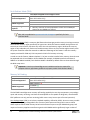
Figure 5 - Example of two 16GB (2Rx8) RDIMMs with one rank held as spare
In order to support single rank sparing, a system must be populated with at least two memory ranks per
memory channel. The memory capacity reduction due to rank sparing is based on the memory
configuration (number of ranks per channel and size of ranks). After one failover event has occurred, no
further failover can occur in single rank sparing mode.
• Rank per channel capacity reduction impact (assuming same sized ranks) = 1 per number of ranks
o E.g. 4 ranks = 25% reduction
• Largest rank in channel is always held as spare
o E.g. One 32 GB RDIMM (2Rx4) and one 16 GB RDIMM (2Rx8) installed = two 16 GB ranks and
two 8 GB ranks. One of the 16 GB ranks will be held as spare, resulting in a 33% capacity
reduction.
In order to support multi rank sparing, a system must be populated with at least three memory ranks
per memory channel. Like single rank sparing, the memory capacity reduction due to rank sparing is
based on the memory configuration (number of ranks per channel and size of ranks). Up to two failover
events may occur in multi rank sparing mode.
• Rank per channel capacity reduction impact (assuming same sized ranks) = 2 per number of ranks
o E.g. 4 ranks = 50% reduction
• Largest rank in channel is always held as spare
o E.g. One 32 GB RDIMM (2Rx4) and one 16 GB RDIMM (2Rx8) installed = two 16 GB ranks and
two 8 GB ranks. Both 16 GB ranks will be held as spares, resulting in a 66% capacity
reduction.

11 Memory Errors and Dell PowerEdge YX4X Server Memory RAS Features
Memory Mirroring
Memory Mirroring Feature Support Table
Platforms Supported
Intel Platforms:
(Xeon SP Families Only)
AMD Platforms:
DIMMs Supported
x4 DIMMs:
x8 DIMMs:
Memory Configuration
Required
• All identical DIMMs
• Memory channels must be populated as either all one DIMM per
channel or two DIMMs per channel
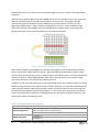
Memory Mirroring is a memory RAS feature available on Intel platforms that provides the highest level
of protection against memory errors – including uncorrectable errors – at the cost of a 50% memory
capacity reduction. This feature essentially works like RAID1 in the storage domain, where a redundant
copy of memory contents is stored in a separate memory location. If an uncorrectable error is detected
during a memory access at one location, then the mirrored content is retrieved instead. There is no
impact to overall memory performance when full mirroring is enabled except during heavy write traffic.
In order to configure for memory mirroring, all memory modules must be identical in size, speed,
density, and technology (RDIMM vs LRDIMM, etc). Additionally, memory channels must be populated
with all one DIMM or all two DIMMs (for example, 24 DIMM systems should have 12 DIMMs or 24
DIMMs installed). Memory mirroring is disabled by default and must be enabled through the BIOS setup
menu.
CPU
DIMM A8
DIMM A2
DIMM A7
DIMM A1
DIMM A9
DIMM A3
DIMM A5
DIMM A11
DIMM A4
DIMM A10
DIMM A6
DIMM A12
CPU
DIMM A8
DIMM A2
DIMM A7
DIMM A1
DIMM A9
DIMM A3
DIMM A5
DIMM A11
DIMM A4
DIMM A10
DIMM A6
DIMM A12
Figure 6 - 6 DIMM/CPU and 12 DIMM/CPU population rules using identical modules
Important: Consult your PowerEdge server installation and service manual for
complete memory population guidelines to properly enable Memory Mirroring.

12 Memory Errors and Dell PowerEdge YX4X Server Memory RAS Features
Fault Resilient Mode (FRM)
Fault Resilient Mode Feature Support Table
Platforms Supported
Intel Platforms:
(Xeon SP Families Only)
AMD Platforms:
DIMMs Supported
x4 DIMMs:
x8 DIMMs:
Memory Configuration
Required
• Memory channels must be populated as either all one DIMM per
channel or two DIMMs per channel
FYI: Dell has published a separate technical whitepaper specifically for Fault
Resilient Mode.
Fault Resilient Mode (FRM) is a memory RAS feature that leverages partial memory mirroring to create a
fault resilient memory region specifically for hypervisors. With this feature enabled, the hypervisor will
ensure that critical memory functions only utilize the mirrored memory region. Because this memory
region is fully redundant, any fatal uncorrectable memory failures in this area that might normally crash
the system should be otherwise averted. An additional advantage of this feature is that the memory
capacity overhead for FRM only 25% compared to 50% in full memory mirroring.
In order to use this feature, VMware vSphere 5.5 or later must be installed. Also, memory channels must
be populated with all one DIMM or all two DIMMs (for example, 24 DIMM systems should have 12
DIMMs or 24 DIMMs installed). Fault Resilient Mode is disabled by default and must be enabled through
the BIOS setup menu.
Important: Consult your PowerEdge server installation and service manual for
complete memory population guidelines to properly enable Fault Resilient Mode.
Memory Self-Healing
Memory Self-Healing Feature Support Table
Platforms Supported
Intel Platforms:
(Xeon SP Families Only)
AMD Platforms:
DIMMs Supported
x4 DIMMs:
x8 DIMMs:
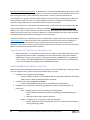
The Dell EMC PowerEdge server memory self-healing capability has two key components: post package
repair and memory retraining. Intel Xeon SP based platforms are capable of doing both, whereas AMD
EPYC platforms can only perform retraining (which occurs every boot as part of normal operation).
Post Package Repair (PPR) is an industry-standard capability, defined by JEDEC, where a memory module
is capable of swapping out degraded rows of memory with spare ones being held in reserve. While
JEDEC requires that all DDR4 memory be built with at least one spare row per DRAM bank group, Dell
requires all memory suppliers manufacture genuine Dell DIMMs with a significantly larger number of

13 Memory Errors and Dell PowerEdge YX4X Server Memory RAS Features
available spare rows. This is done to ensure that PowerEdge servers have a robust self-healing memory
ecosystem.
When the server platform determines that a DRAM row has one or more faulty cells, it can instruct the
DRAM to electrically swap out the old row and replace it with a new one. This happens through
electrical fusing and is a permanent process. Additionally, the PPR process can only occur at the
beginning of a boot process – before memory training and test can occur. Similar to Memory Page
Retirement, deeming which DRAM require Post Package Repair is determined by a proprietary Dell
algorithm that takes into account correctable error rates and error patterns.
Figure 7 - PPR for a row in a bank group of a 4Gb x4 device
PPR is always available on PowerEdge server platforms that support it and will automatically execute
after a system reboot if BIOS deems it necessary. Note that BIOS may automatically promote a warm
reset to a cold reset during this process. In order for PPR to successfully execute, it is recommended that
users do not swap or replace DIMMs between boots when receiving memory error event messages,
unless instructed to do so by Dell technical support personnel.
In addition to PPR, the PowerEdge server memory self-healing process also includes memory re-training.
Memory training is the process by which the CPU initializes, calibrates, and tunes the link between itself
and the memory modules. While performing full memory training can help to ensure that the memory
bus operates at the highest level of signaling integrity, it is also a time-consuming process that directly
impacts server boot times. Therefore, PowerEdge servers only perform this step when necessary, such
as during the memory self-healing process.
Machine Check Architecture Recovery
MCA Recovery Feature Support Table
Platforms Supported
Intel Platforms:
(Xeon SP Gold, Platinum Families Only)
AMD Platforms:
DIMMs Supported
x4 DIMMs:
x8 DIMMs:

14 Memory Errors and Dell PowerEdge YX4X Server Memory RAS Features
Machine Check Architecture Recovery, or MCA Recovery, is an advanced RAS feature which when used in
conjunction with supported operating systems, can prevent some types of uncorrectable memory errors
from crashing the entire system. Essentially, the processor’s memory controller will detect an
uncorrectable error, signal to the OS that the detection has occurred for a memory page and allow the
OS to gracefully contain the issue. The outcome depends entirely on the point of UCE detection and
whether the impacted memory is associated with kernel space or user space.
If the uncorrectable error is detected in the execution path, it means that the error was detected at the
point of consumption by the processor. These are considered Software Recoverable Action Required
(SRAR) errors. If the corrupted memory was destined for the kernel space, then the OS will kernel panic
and the system will crash as per normal UCE behavior. If it was destined for user space, then the OS will
kill the associated process without impacting the rest of the system.
If the uncorrectable error is detected in the non-execution path, it means that the error was detected by
memory patrol scrub and was not about to be imminently consumed by the processor. Detection of
these unconsumed uncorrectable errors are marked in the System Event Log as a critical event,
MEM9072: “The system memory has faced uncorrectable multi-bit memory errors in the non-execution
path of a memory device at the location <location>.”
Other Memory RAS Capabilities on PowerEdge servers
• Memory Map Out – If critical failures (such as uncorrectable errors) are detected in the memory
training and test phase of POST, PowerEdge servers will automatically map out the affected
DIMMs from the system memory pool. This prevents the faulty DIMM from incurring potential
service outages. The affected DIMM will not be mapped back into the memory pool until there
is a memory configuration change (such as a DIMM replacement).
Achieving Maximum Memory Up Time
Based on the memory RAS features discussed in the previous section, the following is a summary of how
users can configure their systems to achieve maximum memory up time:
• Configure server using genuine Dell DIMMs
o Benefit: Memory modules are fully validated and assured by Dell; additional self-healing
(PPR) resources above and beyond industry standards
• Configure server with x4 DRAM based DIMMs
o Benefit: Single DRAM Device Correction (and ADDDC on Intel platforms)
• Configure server to operate in the following redundancy modes (in descending order of
protection):
o Best – Configure server to operate in Memory Mirroring Mode
▪ Benefit: RAID1 level memory protection, significantly reduced probability of
UCEs
▪ Downside: 50% memory capacity reduction
o Better – Configure server to operate in Fault Resilient Mode
▪ Benefit: Significantly reduced probability of UCEs in critical portions of memory
used by operating systems

15 Memory Errors and Dell PowerEdge YX4X Server Memory RAS Features
▪ Downside: 25% memory capacity reduction, available for VMware vSphere 5.5
or higher only
o Good – Configure server to operate in Rank Sparing Mode
▪ Benefit: Run-time elimination of memory ranks that are operating in a degraded
state due to a large number of correctable errors
▪ Downside: Varying amount of memory capacity reduction depending on
memory configuration
• Configure server to run memory patrol scrub in ‘Extended Mode’
o Benefit: Patrol scrub will run every four hours (instead of 24); increased frequency will
reduce the accumulation of errors in areas of memory with low utilization and thus not
being corrected by demand scrub
• Configure server with Intel Xeon SP processors with Advanced RAS capabilities (Gold or Platinum
family) or AMD EPYC processors
o Benefit: Enables MCA Recovery to prevent uncorrectable errors in user memory space
from crashing the host
It is also recommended that users keep their PowerEdge server firmware up to date, especially server
BIOS. This is because even after products ship, PowerEdge server development continuously works to
improve its RAS algorithms and behaviors for an optimal customer experience. Users will also benefit
from keeping BIOS up to date by receiving regular maintenance releases to their platform memory
reference code.
FYI: Memory Reference Code (MRC) is a BIOS code that performs memory training,
configuration, and link optimization.
Recommended User Actions When Encountering Memory Errors
The following is a list of the most common memory errors (as reported in the system event log) and the
recommended user response actions:
• MEM0001 – This is an indication that the system has encountered an uncorrectable memory
error at the specified DIMM location in the event message.
o Recommended Response Action: Contact Dell technical support.
• MEM0005 – This is an indication that the system is encountering correctable errors at the
specified DIMM location and would benefit from Dell memory self-healing.
o Recommended Response Action: Reboot the system at the earliest convenience.
PowerEdge server BIOS will initiate the self-healing process automatically (note that
BIOS may initiate more reboots during this process). Do not remove or swap the DIMM
at the specified location in the event message.
• MEM0701 – Same as MEM0005.
• MEM0702 – Same as MEM0005.
• MEM0802 – Same as MEM0005.
• MEM0805 – This is an indication that the system is unable to successfully perform memory self-
healing at the specified DIMM location in the event message.
o Recommended Response Action: Contact Dell technical support.
• MEM9072 – Same as MEM0001.

16 Memory Errors and Dell PowerEdge YX4X Server Memory RAS Features
Applicable Platforms
The following platforms are considered PowerEdge YX4X servers and are therefore covered by this
document:
Important: Subsequent to the publication of this document, Dell may continue to
add products to its YX4X server lineup. If a product is not listed below, please
consult with a Dell sales or support representative to confirm the server
generation.
Additionally, PowerEdge leveraged products such as some Precision workstations,
OEM, DSS, and ESI products may also be covered by this document. Please consult
with a Dell sales or support representative to confirm.
Intel Xeon E or less Platforms
Intel Xeon SP Platforms
AMD EPYC Platforms
• PowerEdge T40
• PowerEdge T140
• PowerEdge T340
• PowerEdge R240
• PowerEdge R340
• PowerEdge T440
• PowerEdge T640
• PowerEdge C4140
• PowerEdge C6420
• PowerEdge XR2
• PowerEdge R440
• PowerEdge R540
• PowerEdge R640
• PowerEdge R740
• PowerEdge R740xd
• PowerEdge R740xd2
• PowerEdge R840
• PowerEdge R940
• PowerEdge R940xa
• PowerEdge M640
• PowerEdge MX740c
• PowerEdge MX840c
• PowerEdge R6415
• PowerEdge R7415
• PowerEdge R7425
Legal Notices
THIS WHITE PAPER IS FOR INFORMATIONAL PURPOSES ONLY, AND MAY CONTAIN TYPOGRAPHICAL
ERRORS AND TECHNICAL INACCURACIES. THE CONTENT IS PROVIDED AS IS, WITHOUT EXPRESS OR
IMPLIED WARRANTIES OF ANY KIND. Copyright © 2020 Dell Inc. or its subsidiaries. All Rights Reserved.
Dell Technologies, Dell, EMC, Dell EMC and other trademarks are trademarks of Dell Inc. or its
subsidiaries.
Intel and Xeon are trademarks of Intel Corporation or its subsidiaries.
AMD and AMD EPYC are trademarks of Advanced Micro Devices, Inc.
Other trademarks may be trademarks of their respective owners.

17 Memory Errors and Dell PowerEdge YX4X Server Memory RAS Features
References
[1]
P. Restle, J. Park and B. Lloyd, "DRAM Variable Retention Time," IEEE, 1992.
[2]
K. Aadithya, A. Demir, S. Venugopalan and J. Roychowdhury, "Accurate Prediction of Random
Telegraph Noise Effects in SRAMs and DRAMs," IEEE, 2013.
[3]
"Reed–Solomon error correction," Wikipedia, [Online]. Available:
https://en.wikipedia.org/wiki/Reed%E2%80%93Solomon_error_correction.
[4]
V. Sridharan and D. Liberty, "A study of DRAM failures in the field," IEEE, 2012.
[5]
A. Hwang, S. Ioan and B. Schroeder, "Cosmic rays don't strike twice: understanding the nature of
DRAM errors and the implications for system design," ACM, 2012.
© 2020 Dell Inc. or its subsidiaries. All Rights Reserved. Dell, EMC and other trademarks are trademarks of Dell Inc. or its
subsidiaries. Other trademarks may be trademarks of their respective owners.
-
 1
1
-
 2
2
-
 3
3
-
 4
4
-
 5
5
-
 6
6
-
 7
7
-
 8
8
-
 9
9
-
 10
10
-
 11
11
-
 12
12
-
 13
13
-
 14
14
-
 15
15
-
 16
16
-
 17
17


Dell Servers Solution Resources Owner's manual
- Category
- Security device components
- Type
- Owner's manual
- This manual is also suitable for
Ask a question and I''ll find the answer in the document
Finding information in a document is now easier with AI
Related papers
-
Dell Servers Solution Resources Owner's manual
-
-
Dell POWEREDGE R710 Owner's manual
-
-
-
-
-
-
-
Dell PowerEdge R320 Technical Manual
Other documents
-
Compaq BL20p - ProLiant - G2 Overview
-
Intel DBS2400GP2 Datasheet
-
Dell EMC PowerEdge MX740c Technical Manual
-
-
-
Compaq DL580 - ProLiant - 1 GB RAM User manual
-
-
-
-