Page is loading ...

2
Compact ComposTumbler™
Assembly Instructions
Tools You Will Need
• 3/8” wrench
• 7/16” wrench
• 9/16” wrench
• Adjustable wrench
• Plain (or needle nose) pliers
• Flat screwdriver
• Phillips screwdriver
Everything else you will need is included with your
Compact ComposTumbler.
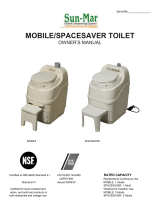
Item Part # Description Qty
8 CT02052-00 Drive Support 1
9 CT01915-00 Drive Handle 1
10 CT02053-00 Brace 2
11 CT02050-00 Frame Leg 2
12 CT02051-00 Strut 2
13 200240 Drive Gear 1
14 CT02048-00 Grip 1
15 CT02049-00 Grip Cap 1
16 CT02047-00 Stub Axle 2
Item Part # Description Qty
1 CT02054-00 Drum Panel A 2
2 CT02055-00 Drum Panel B 1
3 CT01839-00 Door 1
4 200239 Endcap 2
5 CT01698-00 Aerator Base 2
6 CT01699-00 Aerator Cap 2
7 CT01691-01 Tie Rod 3
Drum Assembly Parts
Frame Assembly Parts
1
4
3
2
8
12
13
11
10
14
15
6
5
16
9

3
Item Description Qty
Step 1
1a 10-32 X 3/8 Machine Screw, Slotted Truss Head, Steel, Zinc Plated 5
1b 10-32 Serrated Flange Locknut 5
Step 3
3a
10-24 X 1/2 Special Phillips Truss Head Shoulder Bolt, Steel, Yellow Zinc Plated
12
3b #10 SAE Flat Washer Steel, Zinc Plated 12
3c 10-24 Nylon Insert Lock Nut, NM, Steel, Zinc Plated 12
Step 4 & 5
4a 1/4-20 Acorn Cap Nut High Crown (7/16X19/32), Steel, Zinc Plated 6
5a 1/4-20 X 3 1/4 Hex Head Cap Screw Grade 2, Steel, Zinc Plated 2
5b 1/4-20 Wing Nut Steel, Zinc Plated 2
Step 6
6a
10-32 X 3/8 Machine Screw, Slotted Truss Head, Steel, Zinc Plated
8
6b #10 SAE Flat Washer Steel, Zinc Plated 4
6c #10 Medium Split Lock Washer, Steel, Zinc Plated 4
6d 10-32 Hex Nut Grade 2, Steel, Zinc Plated 4
6e 10-32 Serrated Flange Locknut 4
6f Latch Hook, Zinc Plated 2
6g Latch, Steel, Zinc Plated 2
Step 7 & 8
7a
#6 X 5/16 Phillips Pan Head Type B Sheet Metal Screw, Steel Zinc Plated
1
8a 1/8 X 3/4 Cotter Pins Stl Zinc 1
Step 10
10a 3/8 X 1 1/2 Fender Washer Steel, Grade 2, Zinc Plated 2
10b 3/8-16 Hex Two Way Locknut , Steel, Zinc Plated 2
10c 3/8-16 X 4 Hex Head Cap Screw, Grade 2, Steel, Zinc Plated 2
Step 11
11a 1/4-20 X 3/4 Hex Head Cap Screw, Grade 2, Steel, Zinc Plated 1
11b 1/4-20 X 1 1/2 Hex Head Cap Screw, Grade 2, Steel, Zinc Plated 6
11c 1/4 Medium Split Lock Washer, Steel, Zinc Plated 7
11d 1/4-20 Finished Hex Nut Steel , Zinc Plated 7
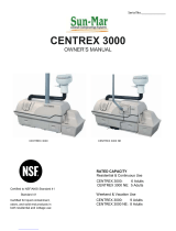
Hardware for the Compact ComposTumbler
1a
4a
7a
11a 11b
10a
10b
10c
11c
11d
8a
5a
6a
5b
6b
6c
6e
6f
6g
6d
1b
3a
3b
3c
STEP 1
STEP 4 & 5
STEP 7 & 8
STEP 6
STEP 11
STEP 10
STEP 3
All hardware can be found in the enclosed hardware
bags. You will see that the items needed for each
step have been grouped together.

4
ATTENTION! Your Compact ComposTumbler may be too large to t through some doorways when
assembled. You should build it in a space with easy access to the area where it will be used.
Go to:
Mantis.com/composterhelp
for a step-by-step instruction
video that will have you
composting in no time!
WHAT YOU’LL NEED
Tools: Regular screwdriver
3/8” wrench
Hardware: 1a - (5) 10-32 x 3/8 Machine screw (silver)
1b-(5)10-32Serratedangelocknut
Parts: Item 1 - (2) Drum panel segments
DRUM ASSEMBLY
STEP 1 – JOINING THE DRUM PANELS
1.1
Placethedrumpanels(item1)onaatsurfacewiththemixingnsfacingup.
Assembly is divided into two major sub-assemblies: Drum and Support Frame.
Mixing Fins

5
WHAT YOU’LL NEED
Tools: None
Hardware: None
Parts: Item 4 - (1) Endcap
(2) Foam Pads
Drum body assembly (from step 1)
STEP 2 – DRUM ASSEMBLY
1.2
2.1
Alignthembymatchinguptheholesinthens.Fastenthepanelstogetherwiththescrews(1a)andserrated
nuts (1b). Use the regular screwdriver and 3/8” wrench to tighten the nuts.
Remove2foampadspackagedinsideofthecardboardspacerandplacethemontheoor.Placetheendcap(Item4)withthe
“Compact ComposTumbler” lettering facing down—on the pads.
Cardboard Spacer
Foam Pads
Foam Pads

6
2.2
Placetheedgesofthedrumbodyassemblyfromstep1insidetheendcap.Besuretoplacethensyou
joined in step 1 in the alignment slot near the screen of the vent opening.
Notethatthensontheendofthedrumbody
extend beyond the slots.
Step 2 Complete
Alignment Slot
Fin

7
3.1 3.2
WiththensontheDrumPanelB
opening facing into the drum, insert
drum panel B into the remaining open
space in the endcap.
Align the holes and fasten drum panel B to the drum with the shoulder bolts,
washers, and lock nuts.
WHAT YOU’LL NEED
Tools: Philips screwdriver
3/8” wrench
Hardware: 3a - (12) ½” Philips truss head shoulder bolts
3b - (12) Flat washers
3c - (12) Nylon insert lock nuts
Parts: Item 2 - (1) Drum Panel B
WHAT YOU’LL NEED
Tools: 7/16” wrench
Adjustable wrench
Hardware: 4a - (6) ¼” Acorn cap nuts
Parts: Item 4 - (1) Endcap
Item 7 - (3) Tie rods
STEP 3 – DRUM PANEL B ASSEMBLY
STEP 4 – ENDCAP INSTALLATION

8
4.1 4.2
5.1 5.2
5.3
Place the second endcap on the open end of the
assembled drum. Note that when the endcap
is properly aligned, the vent openings will be on
oppositesidesofthesamecentermixingn.
Thread an acorn cap nut onto one end of each of the tie
rods (2-3 turns only) and insert the rods trough the holes in
the end cap. Guide the other end of each tie rod through the
hole in the opposite endcap. Reach out under the endcap
and thread acorn cap nuts over the other ends of the tie
rods. Tighten all acorn cap nuts with the wrenches.
Insert a 3-1/4” long Hex head
cap screw through the aerator
base and position the two pieces
on the outside of the door as
shown below.
Slide the aerator cap over the
hex head screw and fasten with
thewingnut(ngertightonly)
Repeat steps 5.1 and 5.2 with the second aerator base and cap.
WHAT YOU’LL NEED
Tools: None
Hardware:
5a - (2) ¼-20 x 3-1/4” Hex head cap screws
5b - (2) ¼-20 Wing nuts
Parts: Item 3 - (1) Door
Item 5 - (2) Aerator base
Item 6 - (2) Aerator cap
STEP 5 – ENDCAP INSTALLATION
Aerator Base
Aerator Cap

9
6.2
Position the Latch Hooks on the other side of the panel
opening with the hook ends toward the opening and attach
themwiththe#10screws(6a),atwashers(6b),splitlock
washers(6c),andhexnuts(6d).Besuretheatwasher,
lock washer and nut are on the underside of the panel in the
recess, with the Bolt head on top of the Latch Hook. Use
the screwdriver and 3/8” wrench to tighten the latch hooks.
WHAT YOU’LL NEED
Tools: Flat screwdriver
3/8” wrench
Hardware: 6a – (8) 10-32 x 3/8” machine screws
6b-(4)#10atwashers
6c - (4) #10 split lock washers
6d – (4) 10-32 hex nuts
6e–(4)10-32serratedangelocknuts
6f - (2) Latch hooks
6g - (2) Latches
Parts: Complete Drum assembly (from step 4)
STEP 6 – LATCH/LATCH HOOK INSTALLATION
Door Opening
6.1
Attach the latches (6g) to one side of the door
opening with the hooks of the latches positioned
toward the opening. Secure them with #10 screws
(6a)andserratedangelocknuts(6e)withtheBolt
Head on top of the Latch. Use the screwdriver and
3/8” wrench to tighten the latches.
Door Opening

10
WHAT YOU’LL NEED
Tools: Philips screwdriver
Hardware: 7a - (1) Philips pan head sheet metal screw
Parts: Item 9 - (1) Drive handle
Item 14 - (1) Grip
Item 15 - (1) Grip cap
DRIVE GEAR AND FRAME ASSEMBLY
STEP 7 – INSTALLING THE GRIP
7.1
7.2
Slide the grip onto the end of the drive
handle.
Push the grip cap into the end of the
handle, making sure to align the holes.
Secure the grip cap with the sheet
metal screw and Philips screwdriver.
Grip Cap
Grip

11
8.1
8.2 8.3
Push the drive gear through the tube in the drive support with the gear on the inside of the drive support.
Insert the handle bar in the drive gear and
fasten it with the cotter pin.
Use the pliers to bend the pin leg as shown
below.
WHAT YOU’LL NEED
Tools: Plain (or needle nose) pliers
Hardware: 8a - (1) Cotter pin
Parts: Item 8 - (1) Drive support
Item 13 - (1) Drive gear
STEP 8 – INSTALLING THE DRIVE GEAR

12
WHAT YOU’LL NEED
Tools: None
Hardware: None
Parts: Drive gear and support assembly from step 8.
Assembled Drum from step 6
WHAT YOU’LL NEED
Tools: Adjustable wrench
9/16” wrench
Hardware: 10a - (2) 3/8” x 1-1/2” Fender washer
10b - (2) 3/8” Two way locknut
10c - (2) 3/8” x 4” Hex head cap screw
Parts: Item 16 - (2) Stub axle
Item 11 - (2) Frame leg
STEP 9 – INSTALLING THE DRIVE SUPPORT
STEP 10 – ATTACHING THE FRAME
9.1
Guide the drive gear into the guide recess of
one endcap as shown.
10.3
Insert one of the frame legs into the
open end of the drive support and
align the holes.
10.4
10.5
Fasten the frame leg, drive support, and
endcap using the hex cap screw, washer,
and locknut. Tighten the hardware with the
adjustable and 9/16” wrenches. Note: The
washer and nut should be on the inside of
the drum.
From inside the drum, insert one of the stub axles
through the center hole in the endcap.
10.1
Stub axle
(seen from inside drum)
10.2
On the outside of the endcap, position
the drive support into the channel on
the end of the stub axle
Drive support in stub
axle channel (seen from
outside drum)
Repeat steps 10.1 through 10.4 for
the other end.

13
WHAT YOU’LL NEED
Tools: Adjustable wrench
7/16” wrench
Hardware: 11a - (1) ¼-20 x ¾” Hex head cap screw
11b – (6) ¼-20 x 1-1/2” Hex head cap screw
11c – (7) ¼ Medium split lock washer
11d – (7) ¼-20 Hex nut
Parts: Item 12 - (2) Strut
Item 10 - (2) Brace
STEP 11 – COMPLETING THE FRAME
Positiontheattenedfaceofastrutagainsttheoutsideofthedriveassemblyand
fastenwitha1-12”hexheadcapscrew,lockwasher,andhexnut(ngertighten
only at this point). Note: You should use the end of the strut that does not have a
second hole close to the end.
Push a hex screw through the hole in the end of the frame leg and attach the other
end of the strut. Note: Do not add any washers/nuts at this time.
Repeat with the second
strut on the other side.
11.1
11.3
11.2
Strut

14
Repeat with the second frame leg on the other side.
Attachthesecondbracetotherstusingthe¼x¾”hex
head cap screw, lock washer, and nut.
Use the adjustable and 7/16” wrenches to tighten the
screws and nuts. Note: Remember to tighten the screws
used to connect the struts to the drive assembly in step
11.1.
Place one of the braces onto the screws and fasten it with
lock washers and nuts.
Rotate the braces toward the drum and fasten them to the
middle holes of the struts as shown below.
11.4
11.6
11.8
11.5
11.7
Middle Holes
of Strut

15
Attachthedoorbyttingtheslotsononeside
onto the latch hooks, then closing the door with
the latches on the other side.
Note: Door tension can be adjusted; Latch Hooks
have slots and can be moved up or down if needed
12.1
WHAT YOU’LL NEED
Tools: None
Hardware: None
Parts: Door assembly from step 5
STEP 12 – ATTACHING
Your ComposTumbler is now completely
assembled and ready to use.
Read your operating instructions manual,
“How to Make Superior Compost”, carefully
before starting your first batch of compost.

16
LIMITED WARRANTY
MANTIS extends this limited warranty against defects in material and workmanship for a period of two (2) years from the date
of purchase by the original purchaser.
MANTIS will repair or replace, at its option, any part or parts of the product found to be defective in material or workmanship
during the warranty period. Warranty repairs and replacements will be made without charge for parts or labor. All parts replaced
under warranty will be considered as part of the original product, and any warranty on the replaced parts will expire coincident
with the original product warranty. If you think your ComposTumbler is defective in material or workmanship, you must send it,
along with your proof of purchase (sales receipt) to:
Mantis
1028 Street Road
Southampton, PA 18966
You are responsible for pickup and delivery charges; the product must be returned to us postage paid.
MANTIS assumes no responsibility in the event that the product was not assembled or used in compliance with any assembly,
care, safety, or operating instructions contained in the Owner’s Manual or accompanying the product. This limited warranty does
not cover damages or defects due to normal wear and tear, lack of reasonable and proper maintenance, failure to follow operating
instructions or owner’s manual, misuse, lack of proper storage or accidents [or routine maintenance parts and service].This limited
warranty shall not be effective if your ComposTumbler has been subjected to negligence or has been repaired or altered by
anyone other than an authorized dealer or authorized service center.
MANTIS MAKES NO EXPRESS OR IMPLIED WARRANTIES, REPRESENTATIONS OR PROMISES EXCEPT THOSE
CONTAINED HEREIN. THERE ARE NO OTHER WARRANTIES, INCLUDING WARRANTIES OF MERCHANTABILITY AND
FITNESS FOR A PARTICULAR PURPOSE. ALL WARRANTIES OTHER THAN THE EXPRESS WARRANTY SET FORTH
ABOVE ARE SPECIFICALLY DISCLAIMED. THE DURATION OF ANY IMPLIED WARRANTY, INCLUDING
MERCHANTABILITY AND FITNESS FOR A PARTICULAR PURPOSE, IS LIMITED TO THE DURATION OF THIS WRITTEN
LIMITED WARRANTY. MANTIS DISCLAIMS ALL LIABILITY FOR INDIRECT, INCIDENTAL AND/OR CONSEQUENTIAL
DAMAGES IN CONNECTION WITH THE USE OF THE MANTIS PRODUCTS COVERED BY THIS WARRANTY. SOME
STATES DO NOT ALLOW LIMITATIONS ON HOW LONG AN IMPLIED WARRANTY LASTS AND/OR DO NOT ALLOW THE
EXCLUSION OR LIMITATION OF INCIDENTAL OR CONSEQUENTIAL DAMAGES, SO THAT ABOVE LIMITATIONS AND
EXCLUSIONS MAY NOT APPLY TO YOU. THIS WARRANTY GIVES YOU SPECIFIC LEGAL RIGHTS, AND YOU MAY
ALSO HAVE OTHER RIGHTS WHICH VARY FROM STATE TO STATE.
MANTIS
1028 Street Road
Southampton, PA 18966
(215) 355-9700
1-800-366-6268
©2017 Schiller Grounds Care, Inc. All Rights Reserved.
6/7/16

17
©2017 Schiller Grounds Care, Inc. All Rights Reserved.
If you have any ques tions or problems with
your ComposTumbler assem bly that aren’t
covered by this booklet, please call us at
1-800-366-6268
We’ll be happy to help!
Mantis
1028 Street Road
Southampton, PA 18966
1-800-366-6268
www.mantis.com
1028 Street Rd, Southampton, PA 18966
1-800-366-6268
In the UK, please call us at 0800 988 4828 or
call your local supplier. Freephone from UK BT
landline.
Mantis UK Ltd
Orchard House
Hempshaw Lane,
Stockport,
Cheshire
SK1 4LH
www.mantis.uk.com

©2017 Schiller Grounds Care, Inc. Tous droits réservés.
12
12
MANTIS France Sarl
20, rue des Garennes
57155 MARLY
www.mantis.fr
0 810 21 18 65
Prix d’un appel local
CompostOriginal_NoticeDeMontage_FR_maq1.indd 12 21/01/14 10:27
12
MANTIS SARL
Verbindungsbüro Deutschland
Postfach 10 05 43
66005 SAARBRÜCKEN
0180 3000 208
(9 cent/min)
www.mantis.de.com
CompostOriginal_NoticeDeMontage_DE_maq1.indd 12 21/01/14 10:21
CompostOriginal_NoticeDeMontage_exe.indd 12 21/01/14 10:29
/