Toshiba SD-P4000 User manual

Category
DVD players
Type
User manual
SD-P4000
OWNER’S MANUAL
2
14
21
31
34
43
Introduction
Connections
Basic setup
Basic playback
Advanced playback
Function setup
DIGITAL VIDEO
47
Others
23
TV operation
©2004 Toshiba Corporation
Before operating the unit, please read this manual thoroughly.
14-inch LCD TV/DVD
COMBINATION
*Screen size is approximate.
*
J5N00221C [E] (Cover) 14/09/2004, 8:00 PM1
2
Introduction
CAUTION:
THIS DIGITAL VIDEO PLAYER EMPLOYS A LASER SYSTEM.
TO ENSURE PROPER USE OF THIS PRODUCT, PLEASE
READ THIS OWNER'S MANUAL CAREFULLY AND RETAIN
FOR FUTURE REFERENCE. SHOULD THE UNIT REQUIRE
MAINTENANCE, CONTACT AN AUTHORIZED SERVICE LO-
CATION-SEE SERVICE PROCEDURE.
USE OF CONTROLS, ADJUSTMENTS OR THE PERFORM-
ANCE OF PROCEDURES OTHER THAN THOSE SPECIFIED
HEREIN MAY RESULT IN HAZARDOUS RADIATION EXPO-
SURE.
TO PREVENT DIRECT EXPOSURE TO LASER BEAM, DO NOT
TRY TO OPEN THE ENCLOSURE. VISIBLE LASER RADIA-
TION MAY BE PRESENT WHEN THE ENCLOSURE IS
OPENED. DO NOT STARE INTO BEAM.
Location of the required Marking
The rating sheet and the safety caution
are on the rear of the unit.
CERTIFICATION: COMPLIES WITH
FDA RADIATION PERFORMANCE
STANDARDS, 21 CFR SUBCHAPTER J.
The lightning flash with arrowhead symbol, within an equilateral
triangle is intended to alert the user to the presence of
uninsulated dangerous voltage within the product's
enclosure that may be of sufficient magnitude to constitute a risk
of electric shock.
The exclamation point within an equilateral triangle is intended
to alert the user to the presence of important operating and
maintenance (servicing) instructions in the literature accompa-
nying the appliance.
WARNING: TO PREVENT FIRE OR SHOCK HAZARD, DO NOT EXPOSE THIS APPLIANCE TO RAIN
OR MOISTURE.
CAUTION : TO PREVENT ELECTRIC SHOCK DO NOT USE THIS POLARIZED PLUG WITH AN
EXTENSION CORD, RECEPTACLE OR OTHER OUTLET UNLESS THE BLADES CAN BE
FULLY INSERTED TO PREVENT BLADE EXPOSURE.
FCC NOTICE :
This equipment has been tested and found to comply with the limits for a Class B digital device, pursuant to Part
15 of the FCC Rules. These limits are designed to provide reasonable protection against harmful interference in
a residential installation. This equipment generates, uses and can radiate radio frequency energy and, if not
installed and used in accordance with the instructions, may cause harmful interference to radio communications.
However, there is no guarantee that interference will not occur in a particular installation. If this equipment does
cause harmful interference to radio or television reception, which can be determined by turning the equipment off
and on, the user is encouraged to try to correct the interference by one or more of the following measures:
- Reorient or relocate the receiving antenna.
- Increase the distance between the equipment and receiver.
- Connect the equipment into an outlet on a circuit different from that to which the receiver is connected.
- Consult the dealer or an experienced radio/TV technician for help.
CAUTION: Changes or modifications not expressly approved by the party responsible for compliance with
the FCC (Federal Communications Commission) Rules could void the user's authority to operate
this equipment.
WARNING: Handling the cord on this product or cords associated with accessories sold with this product will
expose you to lead, a chemical known to the State of California to cause birth defects or other
reproductive harm.
Wash hands after handling.
IMPORTANT SAFEGUARDS
RISK OF ELECTRIC SHOCK
DO NOT OPEN
CAUTION
CAUTION:
TO REDUCE THE RISK OF ELECTRIC
SHOCK, DO NOT REMOVE COVER
(OR BACK). NO USER-SERVICEABLE
PARTS INSIDE. REFER SERVICING TO
QUALIFIED SERVICE PERSONNEL.
J5N00221C [E] (P02-05) 14/09/2004, 8:00 PM2
3
Introduction
1. READ INSTRUCTIONS
All the safety and operating instructions should be read before the unit is operated.
2. RETAIN INSTRUCTIONS
The safety and operating instructions should be retained for future reference.
3. HEED WARNINGS
All warnings on the unit and in the operating instructions should be adhered to.
4. FOLLOW INSTRUCTIONS
All operating and use instructions should be followed.
5. CLEANING
Unplug this unit from the wall outlet before cleaning. Do not use liquid cleaners or aerosol cleaners.
Use a soft dry cloth for cleaning the exterior cabinet only.
6. ATTACHMENTS
The manufacturer of this unit does not make any recommendations for attachments, as they may cause
hazards.
7. WATER AND MOISTURE
Do not use this unit near water. For example, near a bathtub, washbowl, kitchen sink, laundry tub, in a wet
basement, or near a swimming pool.
8. ACCESSORIES
Do not place this unit on an unstable cart, stand, tripod, bracket, or table.
The unit may fall, causing serious injury, and serious damage to the unit.
8A. An appliance and cart combination should be moved with care. Quick stops,
excessive force, and uneven surfaces may cause the appliance and cart
combination to overturn.
9. VENTILATION
Slots and openings in the cabinet back or bottom are provided for ventilation,
and to ensure reliable operation of the unit, and to protect it from overheating.
These openings must not be blocked or covered. The openings should never be blocked by placing the unit
on a bed, sofa, rug, or other similar surface. This unit should never be placed near or over a radiator or heat
source. This unit should not be placed in a built-in installation such as a bookcase or rack unless proper
ventilation is provided or the manufacturer’s instructions have been adhered to.
10. POWER SOURCE
This unit should be operated only from the type of power source indicated on the rating plate. If you are not
sure of the type of power supply to your home, consult your appliance dealer or local power company.
11. GROUNDING OR POLARIZATION
This unit is equipped with a polarized alternating-current line plug (a plug having one blade wider than the other).
This plug will fit into the power outlet only one way. This is a safety feature. If you are unable to insert
the plug
fully into the outlet, try reversing the plug. Do not defeat the safety purpose of the grounding-type plug.
12. POWER-CORD PROTECTION
Power-supply cords should be routed so that they are not likely to be walked on or pinched by items placed
upon or against them, paying particular attention to cords at plugs, convenience receptacles, and the point
where they exit from the appliance.
S3126A
PORTABLE CART WARNING
(symbol provided by RETAC)
J5N00221C [E] (P02-05) 14/09/2004, 8:00 PM3
4
Introduction
EXAMPLE OF ANTENNA GROUNDING AS PER THE
NATIONAL ELECTRICAL CODE
ANTENNA
DISCHARGE UNIT
(NEC SECTION 810-20)
ANTENNA LEAD IN WIRE
GROUNDING CONDUCTORS
(NEC SECTION 810-21)
GROUND CLAMPS
POWER SERVICE GROUNDING
ELECTRODE SYSTEM
(NEC ART 250, PART H)
GROUND CLAMP
ELECTRIC SERVICE
EQUIPMENT
13. LIGHTNING
To protect your unit from a lightning storm, or when it is left unattended and unused for long periods of time,
unplug it from the wall outlet and disconnect the antenna or cable system. This will prevent damage to the
unit due to lightning and power line surges.
14. POWER LINES
An outside antenna system should not be located in the vicinity of overhead power lines or other electric
light or power circuits, or where it can fall onto or against such power lines or circuits. When installing an
outside antenna system, extreme care should be taken to keep from touching such power lines or circuits,
as contact with them might be fatal.
15. OVERLOADING
Do not overload wall outlets and extension cords, as this can result in a risk of fire or electric shock.
16. OBJECT AND LIQUID ENTRY
Do not push objects through any openings in this unit, as they may touch dangerous voltage points or short
out parts that could result in fire or electric shock. Never spill or spray any type of liquid into the unit.
17. OUTDOOR ANTENNA GROUNDING
If an outside antenna or cable system is connected to the unit, be sure the antenna or cable system is
grounded to provide some protection against voltage surges and built-up static charges, Section 810 of the
National Electrical Code (NEC), ANSI/NFPA 70, provides information with respect to proper grounding of
the mast and supporting structure, grounding of the lead-in wire to an antenna discharge unit, size of
grounding conductors, location of antenna discharge unit, connection to grounding electrodes, and require-
ments for the grounding electrode.
NEC-NATIONAL ELECTRICAL CODE
S2898A
IMPORTANT SAFEGUARDS
(continued)
18. SERVICING
Do not attempt to service this unit yourself as opening or removing covers may expose you to dangerous
voltage or other hazards. Refer all servicing to qualified service personnel.
For example:
a. When the power-supply cord or plug is damaged.
b. If liquid has been spilled, or objects have fallen into the unit.
c. If the unit has been exposed to rain or water.
d. If the unit does not operate normally by following the operating instructions. Adjust only those
controls that are covered by the operating instructions, as an improper adjustment of other controls
may result in damage and will often require extensive work by a qualified technician to restore the
unit to its normal operation.
e. If the unit has been dropped or the cabinet has been damaged.
f. When the unit exhibits a distinct change in performance, this indicates a need for service.
J5N00221C [E] (P02-05) 14/09/2004, 8:00 PM4
5
Introduction
19. REPLACEMENT PARTS
When replacement parts are required, be sure the service technician uses replacement parts specified by
the manufacturer or those that have the same characteristics as the original part.
Unauthorized substitutions may result in fire, electric shock or other hazards.
20. SAFETY CHECK
Upon completion of any service or repairs to this unit, ask the service technician to perform safety checks to
determine that the unit is in proper operating condition.
21. HEAT
The product should be situated away from heat sources such as radiators, heat registers, stoves, or other
products (including amplifiers) that produce heat.
22. DISC SLOT
Keep your fingers well clear of the disc slot as it is closing. It may cause serious personal injury.
23. CONNECTING
When you connect the product to other equipment, turn off the power and unplug all of the equipment from
the wall outlet. Failure to do so may cause a product damage. Read the owner's manual of the other
equipment carefully and follow the instructions when making any connections.
24. HEADPHONES
When you use the headphones, keep the volume at a moderate level. If you use the headphones continu-
ously with high volume sound, it may cause hearing damage.
25. LASER BEAM
Do not look into the opening of the disc slot or ventilation opening of the product to see the source of the
laser beam. It may cause sight damage.
26. DISC
Do not use a cracked, deformed, or repaired disc. These discs are easily broken and may cause serious
personal injury and product malfunction.
27. LCD
Do not press hard or jolt the LCD panel. It may cause the LCD panel glass to break and injury may occur.
Should the LCD panel be broken and liquid leaks out, do not inhale or swallow it. Doing so may cause
poisoning. If you have got it into your mouth, wash it out and consult your doctor. If your hands or clothes
have touched it, wipe them with alcohol and a cleaning cloth and then wash them well.
28. NOTE TO CABLE TV SYSTEM INSTALLER
This reminder is provided to call the Cable TV system installer’s attention to Article 820-40 of the NEC that
provides guidelines for proper grounding and, in particular, specifies that the cable ground shall be con-
nected to the grounding system of the building, as close to the point of cable entry as practical.
ON DISPOSAL
This product contains mercury. Disposal of mercury may be regulated due to environmental
considerations. For disposal or recycling information, please contact your local authorities
or the Electronic Industrial Alliance : www.eiae.org.
J5N00221C [E] (P02-05) 14/09/2004, 8:00 PM5
6
Introduction
Notes on moisture condensation
Moisture condensation damages the unit. Please
read the following carefully.
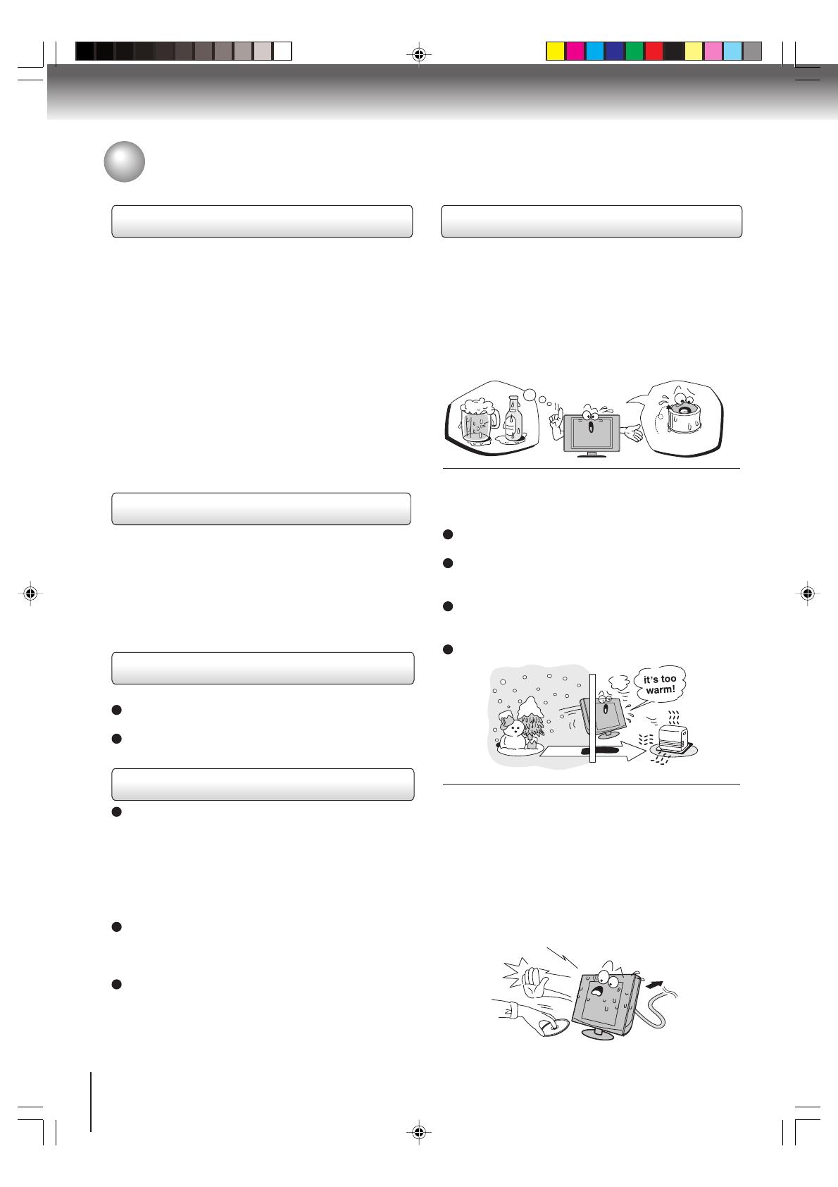
Moisture condensation occurs, for example, when you
pour a cold drink into a glass on a warm day. Drops of
water form on the outside of the glass. In the same way,
moisture may condense on the optical pick-up lens
inside this unit, one of the most crucial internal parts of
the unit.
Moisture condensation occurs during the
following cases.
When you bring the unit directly from a cold place to
a warm place.
When you use the unit in a room where you just
turned on the heater, or a place where the cold wind
from the air conditioner directly hits the unit.
In summer, when you use the unit in a hot and humid
place just after you move the unit from an air
conditioned room.
When you use the unit in a humid place.
Do not use the unit when moisture condensation
may occur.
If you use the unit in such a situation, it may damage
discs and internal parts. Remove the disc, connect
the power cord of the unit to the wall outlet, turn on
the unit, and leave it for two or three hours. After two
or three hours, the unit will have warmed up and
evaporated any moisture. Keep the unit connected to
the wall outlet and moisture condensation will seldom
occur.
Precautions
Notes on handling
Do not shock the LCD panel. It may cause unit
damage and malfunction.
When shipping the unit, the original shipping carton
and packing materials come in handy. For maximum
protection, repack the unit as it was originally packed
at the factory.
Do not use volatile liquids, such as insect spray, near
the unit. Do not leave rubber or plastic products to
contact the unit for prolonged period. They will leave
marks on the finish.
The top and rear panels of the unit may become warm
after a long period of use. This is not a malfunction.
When the unit is not in use, be sure to remove the
disc and turn off the power.
If you do not use the unit for a long period, the unit
may not function properly in the future. Turn on and
use the unit occasionally.
Notes on locating
Place the unit on a level surface. Do not use it on a
shaky or unstable surface such as a wobbling table or
inclined stand. The loaded disc may become dis-
aligned and damage the unit.
When you place this unit near a TV, radio, or VCR,
the playback picture may become poor and the sound
may be distorted. In this case, place the unit away
from the TV, radio, or VCR.
Notes on cleaning
Use a soft, dry cloth for cleaning.
Do not use any type of solvent, such as thinner and
benzine, as they may damage the surface of the unit.
If you use a chemical saturated cloth to clean the unit,
follow that product’s instructions.
Notes on LCD
The color LCD is manufactured using extremely high
precision technology, but even so may include certain
pixels that do not operate properly (that do not light,
that remain lit constantly, etc.). We do our best to
keep the number of these defective pixels to a
minimum, but please understand that they cannot be
completely eliminated even with the most advanced
manufacturing technologies available today.
The fluorescent tube which illuminates the panel from
the inside will deteriorate with use. When the LCD
becomes dim, flickers, or does not illuminate, contact
your dealer for replacement.
The brightness of the LCD monitor differs slightly
depending on the viewing angles. Adjust the angle to
obtain the best viewing. (The recommended angle is
90 degrees to the monitor.)
Wait!
Wall outlet
E
x
a
m
p
l
e
o
f
m
o
i
s
t
u
r
e
c
o
n
d
e
n
s
a
t
i
o
n
!
Optical pick-up
lens
J5N00221C [E] (P06-07) 15/09/2004, 4:21 PM6
7
Introduction
Structure of disc contents
Normally, DVD video discs are divided into titles, and
the titles are sub-divided into chapters. Video CDs and
Audio CDs are divided into tracks.
DVD video disc
Video CD/Audio CD
Each title, chapter or track is assigned a number, which
is called title number, chapter number or track
number respectively.
There may be discs that do not have these numbers.
Notes on copyright
It is forbidden by law to copy, broadcast, show,
broadcast on cable, play in public, and rent copyrighted
material without permission.
DVD video discs are copy protected, and any recordings
made from these discs will be distorted.
This product incorporates copyright protection
technology that is protected by U.S. patents and other
intellectual property rights. Use of this copyright
protection technology must be authorized by
Macrovision, and is intended for home and other limited
viewing uses only unless otherwise authorized by
Macrovision. Reverse engineering or disassembly is
prohibited.
On handling discs
Do not touch the playback side of the disc.
Do not attach paper or tape to discs.
On cleaning discs
Fingerprints and dust on the disc cause picture and
sound deterioration. Wipe the disc from the center
outwards with a soft cloth. Always keep the disc
clean.
Do not use any type of solvent such as thinner,
benzine, commercially available cleaners or antistatic
spray for vinyl LPs. It may damage the disc.
On storing discs
Do not store discs in a place subject to direct sunlight
or near heat sources.
Do not store discs in places subject to moisture and
dust such as a bathroom or near a humidifier.
Store discs vertically in a case. Stacking or placing
objects on discs outside of their case may cause
warping.
Playback side
Title 1 Title 2
Chapter 1 Chapter 2 Chapter 1 Chapter 2 Chapter 3
Track 1 Track 2 Track 3 Track 4 Track 5
DVD video disc
Video CD/Audio CD
Notes on discs
DO NOT
DO
DO
DO NOT
J5N00221C [E] (P06-07) 15/09/2004, 4:21 PM7
8
Introduction
Playable discs
This unit can play the following discs.
You cannot play discs other than those listed above.
You cannot play discs of DVD-RAM, DVD-ROM,
Photo CD, etc., or non standardized discs even if they
may be labeled as above.
Some CD-R/RWs cannot be played back depending
on the recording conditions.
This unit uses the NTSC color system, and cannot
play DVD video discs recorded in any other color
system (PAL, SECAM, etc.).
Because of problems and errors that can occur during the
creation of DVD software and/or the manufacture of DVD
discs, Toshiba America Consumer Products, L.L.C. and
Toshiba of Canada, Ltd. cannot guarantee that this player
will play every feature of every DVD bearing the DVD logo.
As one of the creators of DVD technology, Toshiba DVD
players are manufactured to the highest standards of
quality and, as a result, such incompatibilities are very rare.
If you happen to experience and difficulty playing a DVD on
a Toshiba DVD player, please feel free to call our Contact
listed in “How to Obtain Warranty Services” (page 53).
DVD
video
discs
Disc Mark
Contents
Disc
Size
Maximum
playback time
Video
CDs
Approx. 4 hours
(single sided disc)
Approx. 8 hours
(double sided disc)
Approx. 80 minutes
(single sided disc)
Approx. 160 minutes
(double sided disc)
Approx. 74 minutes
Approx. 20 minutes
8 cm
12 cm
8 cm
12 cm
Audio
+
Video
(moving
pictures)
Audio
+
Video
(moving
pictures)
Audio
CDs
Approx. 74 minutes
Approx. 20 minutes
8 cm
(CD
single)
12 cm
Audio
The following discs are also available.
DVD-R/RW discs of DVD video format
CD-R/CD-RW discs of CD-DA, Video CD, MP3, WMA
or JPEG format
Kodak Picture CD and FUJICOLOR CD format
Some of these discs may be incompatible.
Notes on discs (continued)
About this owners manual
This owner’s manual explains the basic instructions of
this unit. Some DVD video discs are produced in a
manner that allows specific or limited operation during
playback. As such, the unit may not respond to all
operating commands. This is not a defect in the unit.
Refer to instruction notes of discs.
” may appear on the TV screen during operation.
A “
” means that the operation is not permitted by the
unit or the disc.
For example, sometimes it is unable to stop the
playback of copyright message of the disc when the
STOP () button is pressed. Alternatively, the “
” may
also indicate that the feature is not available for the disc.
Notes on region numbers
The region number of this unit is 1. If region numbers,
which stand for their playable area, are printed on your
DVD video disc and you do not find
1
or
ALL
, disc
playback will not be allowed by the player. (In this case,
the unit will display a message on-screen.)
Some DVDs that have no region code label may still be
subject to area restrictions and therefore not playable.
On Video CDs
This DVD supports Video CDs equipped with the PBC
(Version 2.0) function. (PBC is the abbreviation of
Playback Control.) You can enjoy two playback
variations depending on types of discs.
Video CD not equipped with PBC function
(Version 1.1)
Sound and movie can be played on this DVD in the
same way as an audio CD.
Video CD equipped with PBC function
(Version 2.0)
In addition to operation of a Video CD not equipped
with the PBC function, you can enjoy playback of
interactive software with search function by using the
menu displayed on the TV screen (Menu Playback).
Some of the functions described in this owner’s
manual may not work with some discs.
DIGITAL VIDEO
J5N00221C [E] (P08-13) 27/09/2004, 10:42 AM8
9
Introduction
Contents
Introduction
IMPORTANT SAFEGUARDS............................ 2
Precautions ....................................................... 6
Notes on discs................................................... 7
Contents ............................................................ 9
Identification of controls .................................. 10
Connections
Antenna connections....................................... 14
Cable TV connections ..................................... 15
Connecting to optional equipment................... 16
Power source .................................................. 20
Basic setup
Setting the language ....................................... 21
To memorize channels .................................... 22
TV operation
TV operation.................................................... 23
Closed captions............................................... 25
Setting the V-Chip ........................................... 26
Picture control adjustment............................... 28
Adjusting the picture preference ..................... 28
Selecting the color temperature ...................... 29
Sound control adjustment ............................... 30
Stereo and Second Audio Program (SAP) ...... 30
Basic playback
Playing a disc .................................................. 31
Advanced playback
Zooming ......................................................... 34
Locating desired scene .................................. 34
Repeat playback ............................................ 35
A-B Repeat playback ..................................... 35
Program playback .......................................... 36
Random playback .......................................... 36
Changing angles ............................................ 37
Title selection ................................................. 37
DVD menu...................................................... 37
Changing soundtrack language ..................... 38
Subtitles ......................................................... 38
Karaoke playback........................................... 39
Disc status...................................................... 39
To turn off the PBC ........................................ 39
MP3/WMA/JPEG CD operation ..................... 40
Function setup
Customizing the function settings .................. 43
Temporary disabling of rating level
by DVD disc ................................................... 46
Others
Language code list ......................................... 47
Troubleshooting ............................................. 48
Reception disturbances.................................. 50
Specifications ................................................. 51
Limited United States warranty ...................... 52
J5N00221C [E] (P08-13) 15/09/2004, 4:22 PM9
10
Introduction
Top
Identification of controls
See the page in for details.
POWER button
21
31
STOP( ) button
32
EJECT ( ) button
23
VOLUME ( ) buttons
PLAY ( ) button
Remote sensor
31
POWER indicator
CHANNEL (4/3) buttons
22
SKIP ( / ) buttons
33
Front
J5N00221C [E] (P08-13) 15/09/2004, 4:22 PM10
11
Introduction
Side
Rear
Adjusting the angle of the base
You can adjust the
angle of the
TV-screen for 5°
forward or for 15°
backward from
vertical angle.
Hold the base of the
TV while adjusting
the angle.
Left Side Right Side
Disc
slot
PHONES jack
VIDEO IN/AUDIO IN
(L/R) (LINE 2 IN) jacks
DC input jack
COAXIAL DIGITAL AUDIO OUT jack
RF IN jack
VIDEO IN/AUDIO IN (L/R) (LINE 1 IN) jacks
S-VIDEO (LINE 1 IN) jack
COMPONENT VIDEO IN
(Y, P
B
/C
B
, P
R
/C
R
) jacks
Approx. 5
Approx. 15
J5N00221C [E] (P08-13) 15/09/2004, 4:22 PM11
12
Introduction
Remote control
The instructions in this manual describe the function on the remote control. See the page in for details.
*DVD MENU button
Use the DVD MENU button to
display the menu included on
many DVD video discs.
To operate a menu, follow the
instructions in DVD menu.
37
*DVD MENU button
37
PLAY MODE button
35
SKIP buttons
33
CANCEL button
26
16
INPUT SELECT button
24
34
ZOOM button
CH RTN button
TOP MENU button
37
RECALL button
24
PAUSE button
32
REV button
SLEEP button
24
Numbered buttons (0
-
9)
26
SUBTITLE button
38
PLAY button
31
33
FWD button
33
31
STOP button
AUDIO button
30
SLOW buttons
33
POWER button
21
EJECT button
32
Direction buttons
( / / / )
CH +/
-
buttons
21
22
Direct channel selection
buttons (0
-
9)
23
TV/DVD button
31
MUTE button
24
ANGLE button
37
SETUP button
MENU button
43
RETURN button
43
REPEAT A-B button
35
JUMP button
34
ENTER button
21
CLOSED CAPTION button
25
GAME button
16
21
23
VOL +/
-
buttons
Identification of controls (continued)
J5N00221C [E] (P08-13) 15/09/2004, 4:22 PM12
13
Introduction
Replace the compartment
cover.
Install two R03/AAA batteries
(supplied), paying attention to
the polarity diagram in the
battery compartment.
Slide the battery compartment
cover in the direction of the
arrow.
1
23
Aim the remote control at the remote sensor and press control buttons to operate.
Operate the remote control within 30° angle on either side of the remote sensor, up to a distance of approx. 5
meters.
The precautions below should be followed when using batteries in this device:
1. Use only the size and type of batteries specified (R03/AAA).
2. Be sure to follow the correct polarity when installing the batteries as indicated in the battery compartment.
Reversed batteries may cause damage to the device.
3.
Do not mix different types of batteries together (e.g. Alkaline and Carbon-zinc) or old batteries with fresh ones.
4. If the device is not to be used for a long period of time, remove the batteries to prevent damage or injury from
possible battery leakage.
5. Do not try to recharge batteries not intended to be recharged; they can overheat and rupture (follow battery
manufacturers directions).
6. Dispose of used batteries in a designated area. Do not throw batteries into a fire. Attention should be drawn to the
environmental aspects of battery disposal.
Inserting batteries
Operation
Approx. 5 meters
J5N00221C [E] (P08-13) 15/09/2004, 4:22 PM13
14
Connections
75 ohm coaxial cable
(not supplied)
300-75 ohm matching
transformer (supplied)
300-75 ohm matching
transformer (supplied)
UHF 300 ohm
twin-lead wire
(not supplied)
VHF 300 ohm
twin-lead wire
(not supplied)
UHF 300 ohm
twin-lead wire
(not supplied)
VHF 75 ohm
(not supplied)
Antenna
jack
Antenna
jack
Antenna
jack
Combiner
(not supplied)
Antenna
jack
Combiner
(not supplied)
Connect the 75 ohm cable from the combination
VHF/UHF antenna to the antenna jack.
If your combination VHF/UHF antenna has a 300
ohm twin-lead wire, the use of the 300-75 ohm
matching transformer may be necessary.
Connect the UHF 300 ohm twin-lead wire to the
combiner (not supplied). Connect the VHF 300
ohm twin-lead wire to the 300-75 ohm matching
transformer. Attach the transformer to the combiner,
then attach the combiner to the antenna jack.
Connect the VHF 75 ohm cable and UHF 300 ohm
twin-lead wire to the combiner (not supplied).
Attach the combiner to the antenna jack.
Combination VHF/UHF antenna (Separate VHF and UHF 300 ohm twin-lead wires)
Antenna connections
If you are using an indoor or outdoor antenna, follow the instructions below that correspond to your antenna system. If
you are using a cable TV service (CABLE), see page 15 for Cable TV connections.
Separate VHF/UHF antennas (75 ohm VHF cable and 300 ohm UHF twin-lead wires)
Combination VHF/UHF antenna (Single 75 ohm cable or 300 ohm twin-lead wire)
J5N00221C [E] (P14-25) 15/09/2004, 4:23 PM14
15
Connections
For basic cable service not requiring a converter/descrambler
box, connect the Cable TV 75 ohm coaxial cable directly to the
Antenna jack on the back of the TV/DVD.
75 ohm
coaxial cable
If you subscribe to a cable TV service in which basic channels are unscrambled and premium channels require the
use of a converter/descrambler box, you may wish to use a signal splitter and an A/B Switch box (available from the
cable company or an electronics supply store). Follow the connections shown below. With the switch in the “B”
position, you can directly tune any nonscrambled channels on your TV/DVD. With the switch in the “A” position, tune
your TV/DVD to the output of the converter/descrambler box (usually channel 3 or 4) and use the converter/
descrambler box to tune scrambled channels.
Incoming
75 ohm
Cable TV
75 ohm cable to
TV/DVD
Antenna
jack
Antenna
jack
Converter/
descrambler
If you subscribe to a cable TV service which requires the use of a converter/descrambler box, connect the
incoming 75 ohm coaxial cable to the converter/descrambler box. Using another 75 ohm coaxial cable, connect
the output jack of the converter/descrambler box to the antenna jack on the TV/DVD. Follow the connections
shown below. Set the TV/DVD to the output channel of the converter/descrambler box (usually channel 3 or 4)
and use the converter/descrambler box to select channels.
For subscribers to basic cable TV service
For subscribers to scrambled cable TV service
For subscribers to unscrambled basic cable TV service with scrambled
premium channels
Splitter
B
A
Incoming
75 ohm
Cable TV
A/B switch
75 ohm cable
to TV/DVD
Converter/
descrambler
Antenna
jack
Cable TV connections
This TV/DVD has an extended tuning range and can tune most cable channels without using a Cable TV converter box.
Some cable companies offer “premium pay channels” in which the signal is scrambled. Descrambling these signals for
normal viewing requires the use of a descrambler device which is generally provided by the cable company.
J5N00221C [E] (P14-25) 15/09/2004, 4:23 PM15
16
Connections
Press INPUT SELECT to select the desired mode to use the TV as a monitor.
Operate your VCR as usual.
You can enjoy playing a TV game on the screen by adjusting to suitable brightness for your eyes.
1. Connect a TV Game to the TV/DVD.
2. Press GAME. The GAME mode screen appears.
This TV/DVD has the GAME mode function (see page 24).
Left side
Camcorder
To Audio/Video OUT
Audio/Video cable (not supplied)
Left side
Audio/Video cable (not supplied)
To Audio/Video OUT
INPUT SELECT
GAME
Connecting to a VCR
Connecting to a TV Game
Connecting to optional equipment
You can enjoy VCR, camcorder or TV game with connection to external
input.
Notes:
You can also change the TV screen to the desired mode by pressing the CH +/– buttons.
The TV/DVD can also be used as a display device for many video games. However, due to the wide variety of different types of signal
generated by these devices and subsequent hook-up variations required, they have not all been included in the suggested connection
diagrams. You'll need to consult each component's Owner's Manual for additional information.
: Signal flow
: Signal flow
: Signal flow
Using the audio/video inputs
Press INPUT SELECT repeatedly to select the desired mode.
“LINE1”, “LINE2”, “GAME”, “COMPONENT” or TV channel will display on the screen for 4 seconds.
Note: In the DVD mode this key will not operate.
LINE 1
To Audio/Video OUT
Left side
(yellow)
(red)
(white)
Audio/Video cable
(not supplied)
VCR
(yellow)
(red)
(white)
(yellow)
(red)
(white)
TV Channel LINE 1
(Rear lower left)
LINE 2
GAME (LINE 2 IN)COMPONENT
(Left side)
To AUDIO(L/R)/VIDEO IN
Note: Picture might be muted for some VCR playback. This is not a malfunction of this unit.
To playback from the camcorder, connect the camcorder to the TV/DVD as shown.
Connecting to a camcorder
J5N00221C [E] (P14-25) 15/09/2004, 4:23 PM16
17
Connections
Connecting to an optional equipment with S-video output
If you connect a VCR with an S-VIDEO cable to the S-VIDEO IN jack on the rear lower left of the TV/DVD, you
must also connect the audio cables to the AUDIO IN jacks on the rear lower left of the TV/DVD (LINE 1 IN). The
S-VIDEO cable only carries the video signal. The audio signal is separate.
Note: When the S-VIDEO cable and the standard video cable are connected at the same time, the S-video cable takes precedence.
Rear lower left of the TV
Ex. VCR with S-Video
To S-VIDEO OUT
To Audio (L/R) OUT
To AUDIO (L/R) IN
To S-VIDEO IN
Audio cable (not supplied)
S-Video cable (not supplied)
Connecting an optional equipment with ColorStream
®
(Component video) output
Your TV/DVD is capable of using ColorStream
®
(component video). Connecting your TV/DVD to a component
video compatible DVD player, such as a Toshiba DVD player with ColorStream
®
can greatly enhance picture
quality and performance.
The ColorStream
®
inputs on this unit are for use with devices that output 480i interlaced signals and 480p progressive signals. This
unit will not accept or display 720p progressive scan signals or 1080i interlaced high-definition signals. If you connect a high-
definition set-top receiver, 720p progressive scan DVD player, or other similar device to the units ColorStream
®
inputs, YOU MUST
SWITCH THE DEVICES OUTPUT TO 480i INTERLACED OR 480p PROGRESSIVE MODE FIRST. Failure to do this will cause a
poor or no picture to display.
Rear lower left of the TV
Ex. DVD player with Component video
Audio cable (not supplied)
Component video cable (not supplied)
To Audio OUT
To Component
Video OUT
To AUDIO (L/R) IN To COMPONENT
(Y, P
B
/C
B
, P
R
/C
R
) IN
Selecting Component input mode
Press INPUT SELECT repeatedly to
select COMPONENT mode.
When using the Component video cable,
an Audio cable must be connected to
AUDIO IN (L/R) (LINE 1 IN) jacks.
COMPONENT
Notes:
Refer to the owners manual of the connected equipment as well.
When you connect the unit to other equipment, be sure to turn off the power and unplug all of the equipment from the wall outlet
before making any connections.
If you place the unit near a tuner or radio, the radio broadcast sound might be distorted. In this case, place the unit away from the
tuner and radio.
J5N00221C [E] (P14-25) 15/09/2004, 4:23 PM17
18
Connections
: Front speaker
: Rear speaker
: Sub woofer
: Center speaker
: Signal flow
Dolby Digital
Dolby Digital is the surround sound technology used in theaters showing the latest movies, and is now available to
reproduce this realistic effect in the home. You can enjoy motion picture and live concert DVD video discs encoded via the
Dolby Digital recording system with this dynamic realistic sound by connecting the TV/DVD to a 6 channel amplifier
equipped with a Dolby Digital decoder or Dolby Digital processor. If you have a Dolby Surround Pro Logic decoder, you will
obtain the full benefit of Pro Logic from the same DVD movies that provide full 5.1-channel Dolby Digital soundtracks, as
well as from titles with the Dolby Surround mark.
Connecting to an amplifier equipped with a Dolby Digital decoder
Manufactured under license
from Dolby Laboratories.
Dolby, Pro Logic, and the
double-D symbol are trade-
marks of Dolby Laboratories.
Amplifier equipped with a
Dolby Digital decoder
To COAXIAL
type digital
audio input
75 coaxial cable (not supplied)
Dolby Surround Pro Logic
You can enjoy the dynamic realistic sound of Dolby Surround Pro Logic by connecting an amplifier and speaker system (right
and left front speakers, a center speaker, and one or two rear speakers).
With an amplifier equipped with a Dolby Digital
Connect the equipment the same way as described in Connecting to an amplifier equipped with a Dolby Digital decoder.
Refer to that amplifiers owners manual and set the amplifier so you can enjoy Dolby Surround Pro Logic sound.
With an amplifier not equipped with a Dolby Digital
Connect the equipment as follows.
This connection is only suitable for Video CDs and Audio CDs.
Amplifier equipped with a
Dolby Surround Pro Logic
*
Connect one or two rear speak-
ers. The output sound from the
rear speakers will be monaural
even if you connect two rear
speakers.
Connecting to an amplifier equipped with a DTS decoder
Digital Theater Systems (DTS)
DTS is a high quality surround technology used in theaters and now available for home use, on DVD video discs or audio CDs.
If you have a DTS decoder or processor, you can obtain the full benefit of 5.1 channel DTS encoded sound tracks on DVD
video discs or audio CDs.
DTS and DTS Digital Out
are trademarks of Digital
Theater Systems, Inc.
Amplifier equipped with
a DTS decoder
To COAXIAL
type digital
audio input
75 coaxial cable (not supplied)
To COAXIAL
type digital
audio input
*
75 coaxial cable (not supplied)
Connecting to an amplifier equipped with a Dolby Surround Pro Logic
*
This section uses the following reference mark.
Rear lower right of the TV
To COAXIAL DIGITAL
AUDIO OUT
To COAXIAL DIGITAL
AUDIO OUT
To COAXIAL DIGITAL
AUDIO OUT
Connecting to optional equipment (continued)
You can enjoy high quality dynamic sounds by connecting the
TV/DVD to optional audio equipment.
J5N00221C [E] (P14-25) 15/09/2004, 4:24 PM18
19
Connections
MPEG2 sound
You can enjoy motion picture and live concert DVD video discs encoded via the MPEG2 recording system with dynamic
realistic sound by connecting an amplifier equipped with an MPEG2 audio decoder or MPEG2 audio processor.
Connecting to an amplifier equipped with an MPEG audio decoder
Connecting to an amplifier equipped with a digital audio input
2 channel digital stereo
You can enjoy the dynamic sound of 2 channel digital stereo by connecting an amplifier equipped with a digital audio input
and speaker system (right and left front speakers).
Note: PCM audio is limited to DVD or CD playback.
Notes:
DO NOT connect the COAXIAL DIGITAL AUDIO OUT jack of the TV/DVD to the AC-3 RF input of a Dolby Digital Receiver.
This input on your A/V Receiver is reserved for Laserdisc use only and is incompatible with the COAXIAL DIGITAL AUDIO
OUT jack of the TV/DVD.
Connect the COAXIAL DIGITAL AUDIO OUT jack of the TV/DVD to the COAXIAL input of a Receiver or Processor.
Refer to the owners manual of the connected equipment as well.
When you connect the TV/DVD to other equipment, be sure to turn off the power and unplug all of the equipment from the
wall outlet before making any connections.
The output sound of the TV/DVD has a wide dynamic range. Be sure to adjust the receivers volume to a moderate
listening level. Otherwise, the speakers may and your hearing be damaged by a sudden high volume sound.
Turn off the amplifier before you connect or disconnect the TV/DVDs power cord. If you leave the amplifier power on, the
speakers may be damaged.
Amplifier equipped with an
MPEG2 audio decoder
To COAXIAL
type digital
audio input
75 coaxial cable (not supplied)
Amplifier equipped with a
Digital audio input
To COAXIAL
type digital
audio input
75 coaxial cable (not supplied)
Rear lower right of the TV
To COAXIAL DIGITAL
AUDIO OUT
To COAXIAL DIGITAL
AUDIO OUT
J5N00221C [E] (P14-25) 15/09/2004, 4:24 PM19
20
Connections
TO USE AC POWER
1. Connect the AC cord to the AC adapter.
2. Connect the AC adapter plug into this units DC input jack.
3. Connect the AC cord into an AC outlet.
Notes:
Make sure to insert the plug of each cord securely.
During use the AC adapter becomes warm. This is not a
malfunction.
WARNING:
DO NOT CONNECT THIS UNIT TO THE POWER USING
ANY DEVICE OTHER THAN THE SUPPLIED AC ADAPTER
OR POWER CORD. THIS COULD CAUSE FIRE,
ELECTRICAL SHOCK, OR DAMAGE.
DO NOT USE WITH A VOLTAGE OTHER THAN THE
POWER VOLTAGE DISPLAYED. THIS COULD CAUSE
FIRE, ELECTRICAL SHOCK, OR DAMAGE.
CAUTION:
DO NOT USE THE AC ADAPTER IF IT IS COVERED BY A
CLOTH ETC., OR PRESSED INTO A NARROW AREA.
THIS RESULTS IN POOR DISSIPATION OF HEAT AND
MAY CAUSE FIRE, ELECTRICAL SHOCK, OR DAMAGE.
WHEN THIS UNIT IS NOT USED FOR A LONG TIME,
(E.G., AWAY ON A TRIP) IN THE INTEREST OF SAFETY,
BE SURE TO UNPLUG IT FROM THE AC OUTLET.
DO NOT PLUG/UNPLUG THE PLUG WHEN YOUR HANDS
ARE WET. THIS MAY CAUSE ELECTRICAL SHOCK.
IF YOU NEED TO REPLACE THE SUPPLIED AC
ADAPTER OR AC CORD, THE SPECIFIED ONE IS
RECOMMENDED. IN THIS CASE, CONTACT THE
DEALER THAT YOU PURCHASED THE UNIT FROM.
Power connection
Power source
2
3
1
AC adapter
(supplied)
AC cord
(supplied)
AC 120V,
60Hz
To DC
input jack
J5N00221C [E] (P14-25) 15/09/2004, 4:24 PM20
  • Page 1 1
  • Page 2 2
  • Page 3 3
  • Page 4 4
  • Page 5 5
  • Page 6 6
  • Page 7 7
  • Page 8 8
  • Page 9 9
  • Page 10 10
  • Page 11 11
  • Page 12 12
  • Page 13 13
  • Page 14 14
  • Page 15 15
  • Page 16 16
  • Page 17 17
  • Page 18 18
  • Page 19 19
  • Page 20 20
  • Page 21 21
  • Page 22 22
  • Page 23 23
  • Page 24 24
  • Page 25 25
  • Page 26 26
  • Page 27 27
  • Page 28 28
  • Page 29 29
  • Page 30 30
  • Page 31 31
  • Page 32 32
  • Page 33 33
  • Page 34 34
  • Page 35 35
  • Page 36 36
  • Page 37 37
  • Page 38 38
  • Page 39 39
  • Page 40 40
  • Page 41 41
  • Page 42 42
  • Page 43 43
  • Page 44 44
  • Page 45 45
  • Page 46 46
  • Page 47 47
  • Page 48 48
  • Page 49 49
  • Page 50 50
  • Page 51 51
  • Page 52 52
  • Page 53 53
  • Page 54 54

Toshiba SD-P4000 User manual

Category
DVD players
Type
User manual

Ask a question and I''ll find the answer in the document

Finding information in a document is now easier with AI