Page is loading ...

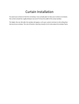
Manual for use and maintenance
AC-2000 3G
Climate Controller
Ag/MIS/Um/Gb-2792-01/21 Rev 1.0
P/N: 117336
AC-2000
3G

© Munters AB, 2018 2
AC-2000 3G
Manual for use and maintenance
Revision: N.1.0 of 01/2021
Product Software: 9.19
This manual for use and maintenance is an integral part of the apparatus together with the attached
technical documentation.
This document is destined for the user of the apparatus: it may not be reproduced in whole or in part,
committed to computer memory as a file or delivered to third parties without the prior authorization of
the assembler of the system.
Munters reserves the right to effect modifications to the apparatus in accordance with technical and
legal developments.

© Munters AB, 2018 3
Index
Chapter page
1
INTRODUCTION -------------------------------------------------------------------------------------------------------------------------------------- 3
1.1
Disclaimer
-----------------------------------------------------------------------------------------------------------------------------------------------------------------------
3
1.2
Introduction
--------------------------------------------------------------------------------------------------------------------------------------------------------------------
3
1.3
Notes
--------------------------------------------------------------------------------------------------------------------------------------------------------------------------------
3
2
INTRODUCTION TO THE AC-2000 3G ------------------------------------------------------------------------------------------- 4
2.1
Keypad
----------------------------------------------------------------------------------------------------------------------------------------------------------------------------
4
2.2
Hot Screens
-------------------------------------------------------------------------------------------------------------------------------------------------------------------
5
2.3
Standard Display
-------------------------------------------------------------------------------------------------------------------------------------------------------
6
2.4
Main Menu Icons
------------------------------------------------------------------------------------------------------------------------------------------------------
7
2.5
Cold Start
-----------------------------------------------------------------------------------------------------------------------------------------------------------------------
8
3
CONTROL MENU ------------------------------------------------------------------------------------------------------------------------------------ 9
3.1
Temperature Curve
---------------------------------------------------------------------------------------------------------------------------------------------------
9
3.1.1
Temperature Curve Help | Set Definitions
.....................................................................
10
3.1.2
Radiant Heaters Help | Set Definitions
...........................................................................
11
3.1.3
Cycle Heaters | Set Definitions
..........................................................................................
12
3.1.4
Variable Heater Help | Set Definitions
...........................................................................
13
3.1.5
Variable Floor Heater | Set Definitions
...........................................................................
16
3.2
Introduction to Humidity, Ammonia, and CO2 Treatment
--------------------------------------------------------------
17
3.3
Humidity Treatment
------------------------------------------------------------------------------------------------------------------------------------------------
17
3.3.1
Humidity Treatment Help | Set Definitions
.....................................................................
18
3.4
CO2 Treatment
--------------------------------------------------------------------------------------------------------------------------------------------------------
19
3.4.1
CO2 Treatment Help | Set Definitions
............................................................................
20
3.5
Min/Max Level
--------------------------------------------------------------------------------------------------------------------------------------------------------
20
3.5.1
By Day and By Soft Days Curve
........................................................................................
21
3.5.2
By Time
........................................................................................................................................
21
3.5.3
Day Soft Min.
............................................................................................................................
22
3.5.4
By Weight
...................................................................................................................................
22
3.6
Static Pressure
-----------------------------------------------------------------------------------------------------------------------------------------------------------
27
3.6.1
Disabling the Static Pressure Sensor
.................................................................................
27
3.6.2
Static Pressure Help | Set Definitions
...............................................................................
28
3.6.3
Multi Stage Tunnel Curtains
.................................................................................................
28
3.7
Control Mode
-----------------------------------------------------------------------------------------------------------------------------------------------------------
29
3.8
System Parameters
-------------------------------------------------------------------------------------------------------------------------------------------------
29

© Munters AB, 2018 4
3.9
Ammonia Treatment
----------------------------------------------------------------------------------------------------------------------------------------------
30
3.9.1
Ammonia Treatment Help | Set Definitions
....................................................................
31
4
DEVICE MENU --------------------------------------------------------------------------------------------------------------------------------------- 32
4.1
Levels of Ventilation
-----------------------------------------------------------------------------------------------------------------------------------------------
33
4.1.1
Levels of Ventilation Help | Set Definitions
....................................................................
34
4.1.2
Wind Chill
...................................................................................................................................
35
4.2
Variable Speed Fan Levels
--------------------------------------------------------------------------------------------------------------------------------
35
4.3
Vent & Curtain Levels
--------------------------------------------------------------------------------------------------------------------------------------------
36
4.3.1
Vent & Curtain Levels Help | Set Definitions
.................................................................
37
4.4
Stir Fan Levels
------------------------------------------------------------------------------------------------------------------------------------------------------------
37
4.5
Stir Fan Program
------------------------------------------------------------------------------------------------------------------------------------------------------
38
4.5.1
Stir Fan Program Help | Set Definitions
..........................................................................
39
4.6
Cool Pad
----------------------------------------------------------------------------------------------------------------------------------------------------------------------
40
4.6.1
Cool Pad Help | Set Definitions
.........................................................................................
41
4.7
Foggers
-------------------------------------------------------------------------------------------------------------------------------------------------------------------------
42
4.7.1
Foggers Help | Set Definitions
...........................................................................................
42
4.8
Light
---------------------------------------------------------------------------------------------------------------------------------------------------------------------------------
43
4.8.1
Light Help | Set Definitions
..................................................................................................
44
4.9
Water & Feed
-----------------------------------------------------------------------------------------------------------------------------------------------------------
45
4.9.1
Water and Feed Help | Set Definitions
..........................................................................
46
4.10
Extra Systems
------------------------------------------------------------------------------------------------------------------------------------------------------------
47
4.11
Water on Demand
-------------------------------------------------------------------------------------------------------------------------------------------------
47
4.11.1
Relay Control
.............................................................................................................................
48
4.11.2
Sensor Control
..........................................................................................................................
48
5
MANAGE MENU ---------------------------------------------------------------------------------------------------------------------------------- 50
5.1
Inventory
----------------------------------------------------------------------------------------------------------------------------------------------------------------------
50
5.2
Feed Inventory
----------------------------------------------------------------------------------------------------------------------------------------------------------
51
5.2.1
Feed Inventory Help | Set Definitions
..............................................................................
51
5.3
Time & Date
---------------------------------------------------------------------------------------------------------------------------------------------------------------
51
5.4
Growth Day & Flock
---------------------------------------------------------------------------------------------------------------------------------------------
52
5.5
Alarm Setting
-------------------------------------------------------------------------------------------------------------------------------------------------------------
52
5.5.1
Alarm Setting Help | Set Definitions
.................................................................................
54
5.6
Alarm Reset
----------------------------------------------------------------------------------------------------------------------------------------------------------------
56
5.7
Password
----------------------------------------------------------------------------------------------------------------------------------------------------------------------
56
6
SCALE MENU ----------------------------------------------------------------------------------------------------------------------------------------- 57
6.1
Scale Layout
--------------------------------------------------------------------------------------------------------------------------------------------------------------
57
6.2
General Settings
------------------------------------------------------------------------------------------------------------------------------------------------------
57
6.2.1
General Settings Help | Set Definitions
..........................................................................
58
6.3
Bird Scale Setting
----------------------------------------------------------------------------------------------------------------------------------------------------
58

© Munters AB, 2018 5
6.3.1
Bird Scale Setting, Version 9.18 and Below
.................................................................
58
6.3.2
Bird Scale Setting, Version 9.19
........................................................................................
59
6.4
Bird Curve/Bird Weight
--------------------------------------------------------------------------------------------------------------------------------------
59
6.4.1
Bird Curve, Version 9.18 and Below
...............................................................................
60
6.4.2
Bird Weight, Version 9.19
...................................................................................................
60
6.5
History
---------------------------------------------------------------------------------------------------------------------------------------------------------------------------
61
6.5.1
History, Version 9.18 and Below
.......................................................................................
61
6.5.2
History, Version 9.19
.............................................................................................................
62
6.6
Feed Conversion
-----------------------------------------------------------------------------------------------------------------------------------------------------
63
6.7
Test
----------------------------------------------------------------------------------------------------------------------------------------------------------------------------------
63
6.8
Calibration
------------------------------------------------------------------------------------------------------------------------------------------------------------------
63
7
HISTORY MENU ------------------------------------------------------------------------------------------------------------------------------------ 65
7.1
Temperature
---------------------------------------------------------------------------------------------------------------------------------------------------------------
65
7.2
Humidity
-----------------------------------------------------------------------------------------------------------------------------------------------------------------------
65
7.3
CO2
-------------------------------------------------------------------------------------------------------------------------------------------------------------------------------
65
7.4
Water
-----------------------------------------------------------------------------------------------------------------------------------------------------------------------------
66
7.5
Feed
--------------------------------------------------------------------------------------------------------------------------------------------------------------------------------
66
7.6
Mortality
-----------------------------------------------------------------------------------------------------------------------------------------------------------------------
66
7.7
Heaters
--------------------------------------------------------------------------------------------------------------------------------------------------------------------------
66
7.8
Radiant Heaters
-------------------------------------------------------------------------------------------------------------------------------------------------------
67
7.9
Alarms
---------------------------------------------------------------------------------------------------------------------------------------------------------------------------
67
7.10
Table of Events
---------------------------------------------------------------------------------------------------------------------------------------------------------
67
7.11
History View
---------------------------------------------------------------------------------------------------------------------------------------------------------------
67
8
TEST MENU --------------------------------------------------------------------------------------------------------------------------------------------- 68
8.1
Relays
----------------------------------------------------------------------------------------------------------------------------------------------------------------------------
68
8.2
Alarm
------------------------------------------------------------------------------------------------------------------------------------------------------------------------------
68
8.3
Analog Sensors
--------------------------------------------------------------------------------------------------------------------------------------------------------
69
8.4
Digital Sensors
----------------------------------------------------------------------------------------------------------------------------------------------------------
69
8.5
Analog Output
---------------------------------------------------------------------------------------------------------------------------------------------------------
69
8.6
Static Pressure
-----------------------------------------------------------------------------------------------------------------------------------------------------------
70
8.7
Communication
--------------------------------------------------------------------------------------------------------------------------------------------------------
70
9
SERVICE MENU ------------------------------------------------------------------------------------------------------------------------------------- 71
9.1
Temperature Calibration
-------------------------------------------------------------------------------------------------------------------------------------
71
9.2
Humidity Calibration
---------------------------------------------------------------------------------------------------------------------------------------------
72
9.3
CO2 Sensor Calibration
------------------------------------------------------------------------------------------------------------------------------------
72
9.4
Static Pressure Calibration
---------------------------------------------------------------------------------------------------------------------------------
73
9.5
Light Sensor Calibration
--------------------------------------------------------------------------------------------------------------------------------------
74
9.6
Feed Calibration
------------------------------------------------------------------------------------------------------------------------------------------------------
74
9.7
Water Calibration
--------------------------------------------------------------------------------------------------------------------------------------------------
75

© Munters AB, 2018 6
9.8
Ventilation Potentiometer Calibration
---------------------------------------------------------------------------------------------------------
75
9.9
Save Settings to SD Card
----------------------------------------------------------------------------------------------------------------------------------
76
9.10
Read from SD Card
-----------------------------------------------------------------------------------------------------------------------------------------------
77
9.10.1
Load Settings Report
...............................................................................................................
77
9.11
WOD Calibration
---------------------------------------------------------------------------------------------------------------------------------------------------
78
9.11.1
WOD Calibration Help | Set Definitions
........................................................................
78
10
INSTALL MENU -------------------------------------------------------------------------------------------------------------------------------------- 79
10.1
Setup
------------------------------------------------------------------------------------------------------------------------------------------------------------------------------
79
10.1.1
Static Pressure Unit Definition
..............................................................................................
80
10.2
Relay Layout
--------------------------------------------------------------------------------------------------------------------------------------------------------------
80
10.2.1
Supported Relays
.....................................................................................................................
80
10.2.2
Relay Layout – Help | Set Definitions
..............................................................................
81
10.3
Analog Sensors
--------------------------------------------------------------------------------------------------------------------------------------------------------
81
10.4
Digital Sensors
----------------------------------------------------------------------------------------------------------------------------------------------------------
82
10.5
Analog Output
---------------------------------------------------------------------------------------------------------------------------------------------------------
83
10.6
Vent/Curtain Setup
------------------------------------------------------------------------------------------------------------------------------------------------
83
10.6.1
Using Time to Calibrate
.........................................................................................................
83
10.6.2
Using a Potentiometer to Calibrate
...................................................................................
84
10.6.3
Vent/Curtain Help | Set Definitions
..................................................................................
84
10.7
Temperature Definition
----------------------------------------------------------------------------------------------------------------------------------------
85
10.8
Fan Air Capacity
-----------------------------------------------------------------------------------------------------------------------------------------------------
86
10.9
House Dimensions
--------------------------------------------------------------------------------------------------------------------------------------------------
86
10.10
Communication
--------------------------------------------------------------------------------------------------------------------------------------------------------
87
11
TECHNICAL SPECIFICATIONS --------------------------------------------------------------------------------------------------------- 88
12
INSTALLATION --------------------------------------------------------------------------------------------------------------------------------------- 89
12.1
Precautions
-----------------------------------------------------------------------------------------------------------------------------------------------------------------
89
12.1.1
Grounding
..................................................................................................................................
89
12.1.2
Filtering
........................................................................................................................................
89
12.1.3
Checking the Battery Level
...................................................................................................
89
12.1.4
Frequency Inverters
.................................................................................................................
89
12.2
Mounting the Unit
---------------------------------------------------------------------------------------------------------------------------------------------------
90
12.3
AC-2000 3G Wiring
--------------------------------------------------------------------------------------------------------------------------------------------
91
12.3.1
Board Layout
.............................................................................................................................
91
12.3.2
Relays
...........................................................................................................................................
92
12.3.3
High Voltage Wiring (Relays)
.............................................................................................
93
12.3.4
Terminal Setup
..........................................................................................................................
94
12.4
Communication Card
-------------------------------------------------------------------------------------------------------------------------------------------
98
12.4.1
Wiring
..........................................................................................................................................
99
12.4.2
Communication Card Grounding
...................................................................................
101

© Munters AB, 2018 7
12.4.3
Termination and 5V Setup
.................................................................................................
101
13
APPENDIX A: DATA OUTPUT ---------------------------------------------------------------------------------------------------------- 104
14
APPENDIX B: INSTALLING A CO2 SENSOR AND SECOND HUMIDITY SENSOR ---- 107
14.1
Humidity Sensor
----------------------------------------------------------------------------------------------------------------------------------------------------
108
14.2
CO2 Sensor
------------------------------------------------------------------------------------------------------------------------------------------------------------
108
15
APPENDIX C: AC-2000 3G PANEL MOUNT ---------------------------------------------------------------------------- 110
15.1
Metal Assembly Precautions
-------------------------------------------------------------------------------------------------------------------------
110
15.2
Panels
--------------------------------------------------------------------------------------------------------------------------------------------------------------------------
110
15.3
Panel Dimensions
-------------------------------------------------------------------------------------------------------------------------------------------------
111
15.4
Connecting the Metal Panels
------------------------------------------------------------------------------------------------------------------------
111
15.4.1
Precautions
..............................................................................................................................
111
15.4.2
Panel Mount Cable Connections
....................................................................................
112
16
APPENDIX D: ELECTRICAL GROUNDING FOR CONTROLLERS ---------------------------------------- 113
16.1
Ground Rods
----------------------------------------------------------------------------------------------------------------------------------------------------------
113
16.2
Ground Wire
----------------------------------------------------------------------------------------------------------------------------------------------------------
114
16.3
Ground Clamps
----------------------------------------------------------------------------------------------------------------------------------------------------
114
16.4
What Should Be Grounded?
------------------------------------------------------------------------------------------------------------------------
114
17
WARRANTY ------------------------------------------------------------------------------------------------------------------------------------------ 115

© Munters AB, 2021 3
1 Introduction
1.1 Disclaimer
Munters reserves the right to make alterations to specifications, quantities, dimensions etc. for production
or other reasons, subsequent to publication. The information contained herein has been prepared by
qualified experts within Munters. While we believe the information is accurate and complete, we make no
warranty or representation for any particular purposes. The information is offered in good faith and with
the understanding that any use of the units or accessories in breach of the directions and warnings in this
document is at the sole discretion and risk of the user.
1.2 Introduction
Congratulations on your excellent choice of purchasing an AC-2000 3G!
In order to realize the full benefit from this product it is important that it is installed, commissioned and
operated correctly. Before installation or using the controller, this manual should be studied carefully. It is
also recommended that it is kept safely for future reference. The manual is intended as a reference for
installation, commissioning and day-to-day operation of the Munters Controllers.
1.3 Notes
Date of release: July 2010
Munters cannot guarantee to inform users about the changes or to distribute new manuals to them.
All rights reserved. No part of this manual may be reproduced in any manner whatsoever without the
expressed written permission of Munters. The contents of this manual are subject to change without notice.

© Munters AB, 2021 4
2 Introduction to the AC-2000 3G
This document describes the AC-2000 3G Precision Mode operation.
Computerized Electronic Controllers such as the AC-2000 3G advance the producer’s ability to grow
high quality eggs by accurately controlling the environment. Instead of struggling with individual
thermostats for heat zones and ventilation, AC-2000 3G brings them all together into one convenient
place with great accuracy. The AC-2000 3G optimizes and precisely applies your equipment and energy
sources to most benefit from the accuracy of your computer and sensors.
The AC-2000 3G coordinates your ventilation equipment in precise levels of ventilation to provide the
optimal fresh air balanced with heating costs. The light and feed clocks provide additional channels for
greater capability. Besides advanced Cooling Pad methods, you benefit from superior stir fan programs
to recover ceiling heat and other features. Precision Mode’s additional features enable you to improve
your profitability significantly.
AC-2000 3G provides a variety of management and history utilities. You can choose from simple
overviews, or fully detailed
by the minute
records of minimum, maximum and average temperatures for
each individual sensor. The unique Table of Events records the moment of every significant action taken
by the AC-2000 3G and, optionally, its operator.
•
Keypad, page 4
•
Hot Screens, page 5
•
Standard Display, page 6
•
Main Menu Icons, page 7
2.1 Keypad
Enter main menu, also acts as "ESC" or "Back" key
Access help screens and graphs
Erase typing mistakes
Enter menus, values, open windows
Scroll up, down, left and right

© Munters AB, 2021 5
Enter values, select options and make selections
Toggle between positive and negative values and mark check boxes
.
2.2 Hot Screens
Many of the keys serve as shortcuts. Here are the main ones:
Software version
Return to standard main screen
Temperature, Humidity Status, and Wind Chill Temperature
NOTE
If two humidity sensors are installed, Hot Screen 2 displays their average.
Curve status
Curtain tunnel, vent, and attic opening positions
Bird scale status
Light status
Analog output status
Temperature sensors
Feed bin status
Scan through Hot Screens for five seconds each

© Munters AB, 2021 6
Air Status (refer to Weight Hot Screen, page 26 for details on this screen)
Stir fans status
Increase/ decrease offset from temperature setting from the standard display only
(hold both keys) – defined in the T
EMPERATURE
C
URVE
H
ELP
|
S
ET
2.3 Standard Display
The main screen consists of the following parts.
1. Sensors: Displays individual sensor readings. Temperature sensors marked with dark squares
form the current average temperature.
o
Filled square: Indicates the sensor participates in the average calculation.
o
Empty square: Indicates the sensor does not participate in the average calculation.
Go to Table 1: Sensor Readings page 104, to view all the possible sensors.
2. Av. Temp: Reports the current average temperature. This example is in Celsius, but yours may be
in Fahrenheit.
SENSORS
AV. TEMP.
ACTIVE
Temp1
37.9°
27.5°
Heat
1
Temp2
16.2°
Heat. Hi
1
Temp3
28.2°
STATUS
Tun. Fan
E. Tmp1
28.8°
08:53:06
Exh. Fan
E. Tmp2
28.4°
Day: 5
Stir
Press.
23
Set:
25.0
Cool P.
Out T.
23.9°
Level:
3
Fogger
Hum. In
58.7%
Min.
Vent
Curt. 1
100%
Hum. Out
61.9%
FanOff:
176
Curt. 2
100%
Weight
0.000
Curt. 3
0%
Weights
0
Curt. 4
0%
4 MESSAGES
Ext. Sys
(2) Low Feed At Bin 2
Alarm
SENSORS
Temp1
37.9°
Temp2
16.2°
Temp3
28.2°
E. Tmp1
28.8°
E. Tmp2
28.4°
Press.
23
Out T.
23.9°
Hum. In
58.7%
Hum. Out
61.9%
Weight
0.000
Weights
0

© Munters AB, 2021 7
3. Active: Displays the output relay list. The filled black boxes indicate active outputs. Controller
also informs the position of inlets and curtains, as well as the number of operating heaters or fans.
Go to Table 2: Output List (Active), page 104 to view all the available readings (ACTIVE).
The ACTIVE screen shows rectangular markers by the outputs. Filled rectangles indicate operating
outputs; empty rectangles indicate outputs that are off.
4. Status: Provides important general information such as the time and ventilation mode.
Go to Table 1: Sensor Readings, page 104 to view all the available readings.
5. Messages: Displays important messages/alarms. The title bar displays the number of important
messages, and if there are several messages, they each appear in turn.
2.4 Main Menu Icons
1. To enter the Main Menu screen, press Menu.
2. To select an option, press Enter.
1. Control temperature, humidity, ventilation, static pressure and system parameters.
Av. Temp
27.5°
ACTIVE
Heat
1
Heat. Hi
1
Tun. Fan
Exh. Fan
Stir
Cool P.
Fogger
Curt. 1
100%
Curt. 2
100%
Curt. 3
0%
Curt. 4
0%
STATUS
08:53:06
Day: 5
Set:
25.0
Level:
3
Min.
Vent
FanOff:
176
4 MESSAGES
(2) Low Feed At Bin 2
Te
mp set to
Time
Controller State
Growth day
Current level of ventilation
Time until
cycle ends operation

© Munters AB, 2021 8
2. Define equipment settings
3. Manage inventory, livestock, and alarm/password settings.
4. Set, calibrate and test bird scales.
5. View history of all controller functions.
6. Test to see switches, relays, communication, and alarms are functioning properly.
7. Calibrate temperature, humidity, ventilation, static pressure, feed, water, read/save to plug.
8. Install sensors, devices, communication, etc.
2.5 Cold Start
To perform a cold start:
1. Disconnect the power cable from the power source.
2. Reapply power while pressing Delete. The Cold Start screen appears.
3. Select Yes.

© Munters AB, 2021 9
3 Control menu
The following sections detail the following functions:
•
Temperature Curve, page 9
•
Introduction to Humidity,
Ammonia, and CO2 Treatment,
page 17
•
CO2 Treatment, page 19
•
Min/Max Level, page 20
•
Static Pressure, page 27
•
Control Mode, page 28
•
System Parameters, page 29
•
Ammonia Treatment, page 30
3.1 Temperature Curve
This screen sets the temperature targets according to the bird age.
1. In
Install > Analog Sensors
(refer to Analog Sensors, page 81), designate the required number
of sensors as temperature sensors. When using more than one sensor, AC-2000 3G begins
treatments based on the average.
2. In
Install > Relays Layout
, define the required number of relays as Heaters.
3. If required, go to
Service > Temperature Calibration
, calibrate the sensors.
4. In
Install > Temperature Definition
, assign specific sensors brood setups, heater zones, and
devices. If a zone does not have an assigned sensors, calculations are based on the current
average temperature.
5. In
Control > Temperature Curve
, define the required target temperature curve
o
Set up to 20 lines, 999 growth days. When a curve is not required, enter temperatures in
the first line only.
Define: Day: Sets growth day. You can program negative growth days up to -7 for
pre-warming. To enter a negative growth day, type the day number followed by
the +/- key.
CONTROL
1. TEMPERATURE CURVE
2. HUMIDITY TREATMENT
3. CO2 TREATMENT
4. MIN/MAX LEVEL
5. STATIC PRESSURE
6. CONTROL MODE
7. SYSTEM PARAMETERS
8. AMMONIA TREATMENT
TEMPERATURE CURVE
Day
Target
Heat
Tunnel
Alarm
Low
High
T.Hi
1
2
3
7
15
21
28
35
42
48
89.0
89.0
87.0
84.0
82.0
79.0
76.0
72.0
70.0
68.0
89.0
89.0
87.0
83.0
81.0
78.0
74.0
70.0
68.0
66.0
100.0
99.0
97.0
91.0
89.0
86.0
81.0
77.0
75.0
73.0
84.0
84.0
82.0
80.0
78.0
75.0
71.0
67.0
63.0
60.0
102.0
102.0
95.0
95.0
93.0
90.0
87.0
84.0
83.0
83.0
103
103
103
103
103
103
103
103
103
103

© Munters AB, 2021 10
Target: Set the desired temperature.
Heat: Set the temperature to stop heat.
Tunnel: Set the temperature for tunnel ventilation to begin.
Alarm Low & High: Set average temperature alarm limits. See Manage | Alarm
Settings for zone alarm settings.
6. In
Manage > Alarm Setting
, set the Sensor Alarms (page 52).
7. If required set the:
o
Temperature Curve Help | Set Definitions, page 10
o
Radiant Heaters Help | Set Definitions, page 11
o
Cycle Heaters | Set Definitions, page 12
o
Variable Heater Help | Set Definitions, page 13
o
Variable Floor Heater | Set Definitions, page 16
3.1.1 T
EMPERATURE
C
URVE
H
ELP
|
S
ET
D
EFINITIONS
While viewing the Temperature Curve menu: Press HELP, select
SET
, and press
ENTER.
•
Temperature Curve Offset: Adjusts all temperature curves by this amount. You can use this to
temporarily adjust all temperatures up or down for special circumstances. The curve appears in
the Status Window, and you can use the ENTER and Up or ENTER and Down hot key
combinations to change the offset.
•
Set Temperature Change Reminder (Diff): Sets the change in set temperature that triggers a
reminder for you to set backup thermostats. Often producers forget to set backup thermostats as
their birds grow from baby chicks to market age, so the AC-2000 3G reminds you. When you
press Enter to acknowledge the reminder, the AC-2000 3G logs it in the Table of Events.
•
Target Temperature Band: The size of the target temperature zone. This "Happy Zone” is
between Target Temperature and (Target Temperature + Band).
•
Heater Temperature Band: Heaters turn on at ‘Band’ degrees below Heat, and turn off at the
Heat Temperature.
NOTE
Heaters operate at minimum level only; however, Radiant Heaters can operate at any
temperature or level below Tunnel.
•
Cool Down Factor (%): Minimum percentage correction towards target during each increase
ventilation level delay. If average temperature does not improve by this amount, the AC-2000
3G increases ventilation by one level.
•
Cool Down Fast Response (Deg.): Set a limit to the maximum degrees per minute of cooling.
If Average Temperature drops more than this in one minute, the AC-2000 3G decreases
ventilation one level to avoid overshooting.
SYSTEM PARAMETERS
TEMPERATURE CURVE
Temperature Curve Offset
Set Temp. Change Reminder (Diff)
Target Temp. Band
Heater Temp. Band
Cool Down Factor (%)
Cool Down Fast Response (Deg.)
Min Vent Below Heat Temp By:
Non Brood Area Diff. From Heat
0.0
3.0
1.5
1.0
15
3.0
ZONE
-3.0

© Munters AB, 2021 11
NOTE
Avoid making this parameter too small or the normal temperature variation caused by timer fans
reduces the ventilation level.
•
Min Vent Below Heat Temp By: Tells controller to go directly to Min Level in some cases.
Select from the following choices:
o
None: Operate by the normal level decrease time delay rule.
o
Zone: Go directly to minimum level if any active temperature sensor reaches heat
temperature.
o
Avg.: Go directly to minimum level if the average temperature reaches heat temperature.
•
Non Brood Area Diff. From Heat: Set differential temperature for non-brood heaters. You
normally use this to set temperatures in unoccupied areas.
NOTE
When set at -99° F the heaters are effectively disabled, since it will probably never go to 99º F
below the heater temperature. Putting this parameter at 0º sets the non-brood areas to the
heater temperature.
3.1.2 R
ADIANT
H
EATERS
H
ELP
|
S
ET
D
EFINITIONS
To configure the radiant heaters:
1. In
Installation > Relay Layout
define at least one relay as a radiant heater (Relay Layout,
page 80).
2. Configure the following parameters:
o
Radiant Low – Differential from Heat Set: Set degree of difference from Heat for LOW
Radiant Heaters to begin working. This differential can be positive or negative. (default:
2.0)
o
Radiant High – Differential (Below Low Set): Set number of degrees below Radiant
Low Heaters for HIGH Radiant Heaters to begin working (default: 1.0). To ensure
proper heater ignition, Radiant High Heaters remain on for the Radiant Ignition Time
along with the Radiant Low Heaters.
o
Radiant Ignition Time (sec): Set number of seconds to power radiant ignition (default:
30).
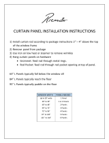
The Heater Temperature Band applies to radiant heaters as well. For example, if the Heat
Temperature is 80º F and the Heater Temperature Band is 1º F, heaters turn on at 79º F and off at
80º F. If the Radiant Low Differential is 2.0º F, radiant heaters turn off at 82º F, and on 1º F below
that (81º F). However, a Radiant High Heater turns on regardless of its temperature setting for the
Radiant Ignition Time whenever the corresponding Radiant Low Heater turns on. This feature
ensures proper flame ignition.
SYSTEM PARAMETERS
TEMPERATURE CURVE
Temperature Curve Offset
Set Temp. Change Reminder (Diff)
Target Temp. Band
Heater Temp. Band
Cool Down Factor (%)
Cool Down Fast Response (Deg.)
Min Vent Below Heat Temp By:
Non Brood Area Diff. From Heat
RADIANT HEATERS
Rad. Low –Diff from Heat Set
Rad. High –Diff (Below Low Set)
Radiant Ignition Time (sec)
0.0
3.0
1.5
1.0
15
3.0
ZONE
-3.0
0.0
1.0
30

© Munters AB, 2021 12
Figure 1: Radiant Heater Differentials
3.1.3 C
YCLE
H
EATERS
|
S
ET
D
EFINITIONS
Heat Cycle means providing heat in conjunction with the ventilation system during minimum ventilation
cycles, using heaters and fans connected to relays. When enabled, heaters operate during the fans’
cycle off time (as defined in the Levels of Ventilation Cycle Timer On and Off parameters). How does it
work?
Between the Heat Temperature and the differential temperature, heaters do not operate. When the
temperature goes below the Heat Off temperature minus the Low Heat Differential:
•
Heaters begin to operate when the exhaust or tunnel fans are off. Heaters operate for the
Minimum On Time.
•
If the temperature continues to drop, heaters operate for longer periods of time, up to the
Maximum On Time (defined in Levels of Ventilation).
•
AC-2000 3G automatically generates a curve.
In this example:
•
Temperature Curve Heat Off is 78°.
•
Low Heat Differential is 1°.
•
High Heat Differential is 8°.
•
Minimum On time is 30 seconds.
•
Cycle Off time is 270 seconds.

© Munters AB, 2021 13
1. Define the required number of heater and exhaust and/or tunnel relays (Relay Layout, page 80).
2. In Control > Control Mode, set the Heater Cycle to Yes.
3. In Control > Temperature Curve > Help, scroll to Cycle Heater.
4. Define:
o
Low Heat Differential: The differential below the Heat Off temperature, at which heating
begins and runs for the minimum amount of time.
o
High Heat Differential: The differential below the Heat Off temperature, at which heating
runs for the maximum amount of time
o
Minimum ON Time: Minimum heating time when the exhaust or tunnel fans are off.
3.1.4 V
ARIABLE
H
EATER
H
ELP
|
S
ET
D
EFINITIONS
The AC-2000 3G Controller enables configuring up to two variable heaters. The heater output changes
according to the output of a 0 – 10 VDC device.
To configure the variable heaters:
1. In
Installation > Analog Output
configure:
a. up to two analog outputs as variable heaters
b. the minimum and maximum voltage output for each heater
2. In
Control > Control Mode > Analog Heat Mode
, define the mode.
•
Linear Heat
•
Proportional Heat
•
Linear Valve
Refer to Control Mode, page 29 for details.
3. In Control > Temperature Curve > Help, define the parameters for each mode.
ANALOG OUTPUT
Out No.
Output
Function
Min
V.Out
Max
V. Out
1
Var. Heater 1
1.0
10.0
2
Var. Heater 2
1.0
10.0

© Munters AB, 2021 14
3.1.4.1 Linear Heat
When Linear Mode is enabled:
•
Between the Heat Temperature and the Target temperature, heaters do not operate (meaning,
the output voltage is 0).
•
Between the Heat Temperature and the Low Difference Below Heat, heaters operate at the
minimum voltage output.
•
If the temperature continues to drop, the voltage output increases until it reaches the maximum
voltage output at the High Difference below Heat.
In this example:
•
Target Temperature is 80°
•
Temperature Curve Heat Off is 78°.
•
Low Heat Differential is 1°.
•
High Heat Differential is 8°.
o
If the temperature is between 77° to 78°, the output voltage is the minimum voltage
defined in Installation > Analog Output (1 volt in this example).
o
If the temperature continues to drop, the output voltage increases until it reaches the
maximum voltage defined in Installation > Analog Output. Output increases or
decreases to keep the temperature within the Target Temperature and Heat Off band.
•
Define the parameters:
o
Low Difference Below Heat: Temperature difference between the Heat Off parameter
at which the variable heater begins to function.
SYSTEM PARAMETERS
RADIANT HEATERS
Rad. Low –Diff from Heat Set
Rad. High –Diff (Below Low Set)
Radiant Ignition Time (sec)
VARIABLE HEATER
Low Diff Below Heat
High Diff Below Heat
0.0
1.0
30
1.0
8.0

© Munters AB, 2021 15
o
High Difference Below Heat: Temperature at which the heater begins to operate at
maximum output.
3.1.4.2 Proportional Heat
Proportional Heat works in manner similar to Linear Mode. The difference is that Proportional Heat
features a delay time.
•
When the temperature falls below the user-defined point, the heaters begin operating at their
minimum output.
•
After the response time passes, AC-2000 3G checks the temperature. If it is still below the
defined point, AC-2000 3G increases the voltage by a certain amount (this amount of the
increase cannot be changed).
•
After the response time passes, the process is repeated until heaters operate at their maximum
output.
•
Define the parameters.
o
Difference Above Heat to Stop Heater: Differential from target temperature at which
the heater runs at minimal input
o
High Difference Below Heat: High Difference Below Heat: Temperature at which the
heater begins to operate at maximum output
o
Response Time (seconds): Amount of time before the controller begins to change the
ventilation.
3.1.4.3 Linear Valve
Linear Valve enables defining that variable heater input voltage is always equal to or above the minimum
input defined in Installation > Analog Sensors..
When the Analog Heat Mode is defined as having Linear Valve control, there is always a minimal
voltage input. Therefore, if the minimum voltage is 1 volts:
•
The voltage range is from 1 to 10 volts
o
this corresponds to 10% at 1V and 100% at 10V
SYSTEM PARAMETERS
RADIANT HEATERS
Rad. Low –Diff from Heat Set
Rad. High –Diff (Below Low Set)
Radiant Ignition Time (sec)
VARIABLE HEATER
Diff Above Heat to Stop Heater
High Diff Below Heat
Response Time (seconds)
0.0
1.0
30
1.0
8.0
15
SYSTEM PARAMETERS
RADIANT HEATERS
Rad. Low –Diff from Heat Set
Rad. High –Diff (Below Low Set)
Radiant Ignition Time (sec)
VARIABLE HEATER
Low Diff Below Heat
High Diff Below Heat
0.0
1.0
30
1.0
8.0
/