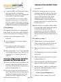
BrandMotion 5000-CA9.pdf Installation guide
- Type
- Installation guide
BrandMotion 5000-CA9.pdf is a device that provides a variety of features to enhance your driving experience. With its ability to integrate with your vehicle's factory display, you can access a range of functions and information without taking your eyes off the road. The device supports both wired and wireless Apple CarPlay and Android Auto, allowing you to seamlessly connect your smartphone and access your favorite apps, navigation, and music.
BrandMotion 5000-CA9.pdf is a device that provides a variety of features to enhance your driving experience. With its ability to integrate with your vehicle's factory display, you can access a range of functions and information without taking your eyes off the road. The device supports both wired and wireless Apple CarPlay and Android Auto, allowing you to seamlessly connect your smartphone and access your favorite apps, navigation, and music.


-
 1
1
-
 2
2
-
 3
3
-
 4
4
-
 5
5
-
 6
6
-
 7
7
-
 8
8
-
 9
9
-
 10
10
-
 11
11
-
 12
12


BrandMotion 5000-CA9.pdf Installation guide
- Type
- Installation guide
BrandMotion 5000-CA9.pdf is a device that provides a variety of features to enhance your driving experience. With its ability to integrate with your vehicle's factory display, you can access a range of functions and information without taking your eyes off the road. The device supports both wired and wireless Apple CarPlay and Android Auto, allowing you to seamlessly connect your smartphone and access your favorite apps, navigation, and music.
Ask a question and I''ll find the answer in the document
Finding information in a document is now easier with AI
Related papers
-
BrandMotion 5000-CA8.pdf Installation guide
-
-
BrandMotion 5000-CA13 Installation guide
-
-
BrandMotion 9002-2781 Installation guide
-
-
-
-
-
Other documents
-
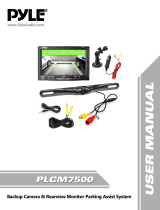 PYLE Audio PL-CM7500 User manual
-
 ASA Electronics JE1029BVM User manual
-
Pyle PLCM4700 Owner's manual
-
-
Pyle PLCM46 User manual
-
 Crimestopper Security Products SECURVIEW SV-7020 User manual
-
Voyager JSB4000 User manual
-
Rear View Safety RVS-770619N Installation guide
-
HTC 99HLR00100 User manual
-


