Grundfos alpha2 l Installation And Operating Instructions Manual

Type
Installation And Operating Instructions Manual

The Grundfos Alpha2 L is an energy-efficient circulator pump designed for heating systems and domestic hot water systems. It features automatic flow adaptation, allowing it to adjust its performance to the actual system requirements. The pump has a user-friendly control panel with a display showing the actual power consumption and eight light fields indicating the pump setting. The Grundfos Alpha2 L is easy to install and operate, making it an ideal choice for homeowners looking to improve the efficiency of their heating system.

The Grundfos Alpha2 L is an energy-efficient circulator pump designed for heating systems and domestic hot water systems. It features automatic flow adaptation, allowing it to adjust its performance to the actual system requirements. The pump has a user-friendly control panel with a display showing the actual power consumption and eight light fields indicating the pump setting. The Grundfos Alpha2 L is easy to install and operate, making it an ideal choice for homeowners looking to improve the efficiency of their heating system.

GRUNDFOS INSTRUCTIONS
GRUNDFOS ALPHA2
Installation and operating instructions
Declaration of Conformity
We, Grundfos, declare under our sole responsibility that the product
GRUNDFOS ALPHA2, to which this declaration relates, is in conformity
with these Council directives on the approximation of the laws of the EC
member states:
Low Voltage Directive (2006/95/EC).
Standards used: EN 60335-1: 2002 and EN 60335-2-51: 2003.
EMC Directive (2004/108/EC).
Standards used: EN 61000-6-2 and EN 61000-6-3.
Bjerringbro, 15th September 2009
Svend Aage Kaae
Technical Director
2
3
Original installation and operating instructions.
CONTENTS
Page
1. Symbols used in this document . . . . . . . . . . . . . . . . . . . . . . . . . . . . . . . . . . . . . . 4
2. General description . . . . . . . . . . . . . . . . . . . . . . . . . . . . . . . . . . . . . . . . . . . . . . . . 5
3. Applications . . . . . . . . . . . . . . . . . . . . . . . . . . . . . . . . . . . . . . . . . . . . . . . . . . . . . . 6
4. Installation . . . . . . . . . . . . . . . . . . . . . . . . . . . . . . . . . . . . . . . . . . . . . . . . . . . . . . . 8
5. Electrical connection . . . . . . . . . . . . . . . . . . . . . . . . . . . . . . . . . . . . . . . . . . . . . . . 11
6. Control panel . . . . . . . . . . . . . . . . . . . . . . . . . . . . . . . . . . . . . . . . . . . . . . . . . . . . . 12
7. Setting the pump . . . . . . . . . . . . . . . . . . . . . . . . . . . . . . . . . . . . . . . . . . . . . . . . . . 14
8. Automatic Night SetBack . . . . . . . . . . . . . . . . . . . . . . . . . . . . . . . . . . . . . . . . . . . . 16
9. Systems with bypass valve between flow and return pipes . . . . . . . . . . . . . . . . 19
10. Start-up . . . . . . . . . . . . . . . . . . . . . . . . . . . . . . . . . . . . . . . . . . . . . . . . . . . . . . . . . . 21
11. Pump settings and pump performance . . . . . . . . . . . . . . . . . . . . . . . . . . . . . . . . . 23
12. Fault finding chart . . . . . . . . . . . . . . . . . . . . . . . . . . . . . . . . . . . . . . . . . . . . . . . . . 25
13. Technical data and installation dimensions . . . . . . . . . . . . . . . . . . . . . . . . . . . . . 26
14. Performance curves . . . . . . . . . . . . . . . . . . . . . . . . . . . . . . . . . . . . . . . . . . . . . . . . 28
15. Features . . . . . . . . . . . . . . . . . . . . . . . . . . . . . . . . . . . . . . . . . . . . . . . . . . . . . . . . . 34
16. Accessories . . . . . . . . . . . . . . . . . . . . . . . . . . . . . . . . . . . . . . . . . . . . . . . . . . . . . . 36
17. Disposal . . . . . . . . . . . . . . . . . . . . . . . . . . . . . . . . . . . . . . . . . . . . . . . . . . . . . . . . . 37
4
Original installation and operating instructions.
1. Symbols used in this document
Warning
Prior to installation, read these installation and operating
instructions. Installation and operation must comply with local
regulations and accepted codes of good practice.
Warning
The use of this product requires experience with and knowledge of
the product.
Persons with reduced physical, sensory or mental capabilities must
not use this product, unless they are under supervision or have been
instructed in the use of the product by a person responsible for their
safety.
Children must not use or play with this product.
Warning
If these safety instructions are not observed, it may result in
personal injury!
Caution
If these safety instructions are not observed, it may result in
malfunction or damage to the equipment!
Note
Notes or instructions that make the job easier and ensure safe
operation.
5
2. General description
Contents:
2.1 The GRUNDFOS ALPHA2 circulator pump
2.2 Advantages of installing a GRUNDFOS ALPHA2.
2.1 The GRUNDFOS ALPHA2 circulator pump
The GRUNDFOS ALPHA2 circulator pump is designed for the circulation
of water in heating systems and domestic hot-water systems.
GRUNDFOS ALPHA2 is the best choice for
underfloor heating systems
one-pipe systems
two-pipe systems.
GRUNDFOS ALPHA2 incorporates a permanent-magnet motor and
differential-pressure control enabling continuous adjustment of the pump
performance to the actual system requirements.
GRUNDFOS ALPHA2 has a user-friendly front-mounted control panel.
See 6. Control panel and 15. Features.
2.2 Advantages of installing a GRUNDFOS ALPHA2
The installation of a GRUNDFOS ALPHA2 means
easy installation and start-up
GRUNDFOS ALPHA2 is easy to install.
Thanks to the AUTO
ADAPT function (factory setting), the pump can, in
most cases, be started without making any settings.
high degree of comfort
Minimum noise from valves, etc.
low energy consumption
Low energy consumption compared to conventional circulator pumps.
The GRUNDFOS ALPHA2 is A-labelled.
Fig. 1 Energy label, A-labelled
TM03 0868 0705
6
3. Applications
Contents:
3.1 System types
3.2 Pumped liquids
3.3 System pressure
3.4 Relative air humidity (RH)
3.5 Enclosure class
3.6 Inlet pressure.
3.1 System types
Fig. 2 Pumped liquids and operating conditions
GRUNDFOS ALPHA2 is suitable for
systems with constant or variable flows where it is desirable to
optimise the setting of the pump duty point
systems with variable flow-pipe temperature
systems where night setback is desired.
3.2 Pumped liquids
Clean, thin, non-aggressive and non-explosive liquids, not containing
solid particles, fibres or mineral oil. See fig. 2.
In heating systems, the water should meet the requirements of accepted
standards on water quality in heating systems, e.g. the German standard
VDI 2035.
In domestic hot-water systems, it is advisable to use GRUNDFOS
ALPHA2 pumps only for water with a degree of hardness lower than
approx. 14 °dH. For water with a higher degree of hardness, a direct-
coupled TPE pump is recommended.
TM03 8921 2707
Warning
The pump must not be used for the transfer of flammable liquids
such as diesel oil, petrol and similar liquids.
7
3.3 System pressure
Maximum 1.0 MPa (10 bar). See fig. 2.
3.4 Relative air humidity (RH)
Maximum 95 %. See fig. 2.
3.5 Enclosure class
IP 42. See fig. 2.
3.6 Inlet pressure
Minimum inlet pressure in relation to liquid temperature. See fig. 2.
Liquid temperature
Minimum inlet pressure
[MPa] [bar]
75 °C 0.005 0.05
90 °C 0.028 0.28
110 °C 0.108 1.08
8
4. Installation
Contents:
4.1 Mounting
4.2 Control box positions
4.3 Changing the control box position
4.4 Insulation of pump housing.
4.1 Mounting
Fig. 3 Mounting the GRUNDFOS ALPHA2
Arrows on the pump housing indicate the liquid flow direction through the
pump.
See 13.2 Installation dimensions – GRUNDFOS ALPHA2 XX-40, XX-50,
XX-60 or 13.3 Installation dimensions – GRUNDFOS ALPHA2 25-40 A,
25-60 A.
1. Fit the two gaskets supplied when the pump is mounted in the pipe.
See fig. 3, pos. A.
2. Install the pump with the motor shaft horizontal. See fig. 3, pos. B.
TM03 8922 2707
9
4.2 Control box positions
Fig. 4 Control box positions
4.3 Changing the control box position
The control box can be rotated in steps of 90 °.
Possible/permissible positions and the procedure of changing the position
of the control box are illustrated in fig. 4, pos. A.
Procedure:
1. Slacken and remove the four hexagon-socket head screws holding the
pump head with a tee key (M4).
2. Turn the pump head to the desired position.
3. Insert and cross-tighten the screws.
TM03 8923 2707
A
Warning
The pumped liquid may be scalding hot and under high pressure!
Drain the system or close the isolating valves on either side of the
pump before the screws are removed.
Caution
When the position of the control box has been changed, fill the
system with the liquid to be pumped or open the isolating valves.
10
4.4 Insulation of pump housing
Fig. 5 Insulation of pump housing
The heat loss from the pump and pipework can be reduced by insulating
the pump housing and the pipe. See fig. 5.
As an alternative, polystyrene insulation shells can be ordered from
Grundfos. See 16. Accessories.
TM03 8924 2707
Note
Limit the heat loss from the pump housing and pipework.
Caution
Do not insulate the control box or cover the control panel.
11
5. Electrical connection
Fig. 6 Electrical connection
The electrical connections and protection must be carried out in
accordance with local regulations.
The motor requires no external motor protection.
Check that the supply voltage and frequency correspond to the values
stated on the pump. See 15.1 Nameplate.
Connect the pump to the mains with the plug supplied with the pump
as shown in fig. 6, steps 1 to 8.
Light in the control panel shows that the electricity supply has been
switched on.
TM03 8925 2707
§
+
!
1
Min. ø5 mm
Max. ø10 mm
7 mm
12 mm
234
Max. 1.5 mm
2
7 mm
17 mm
0
1
Click
567
8
1 x 230V
~
, 50 Hz
-10%
+ 6%
Warning
The pump must be connected to earth .
The pump must be connected to an external mains switch with a
minimum contact gap of 3 mm in all poles.
12
6. Control panel
Contents:
6.1 Elements on the control panel
6.2 Display
6.3 Light fields indicating the pump setting
6.4 Light field indicating the status of Automatic Night SetBack
6.5 Push-button for activation of Automatic Night SetBack
6.6 Push-button for selection of pump setting.
6.1 Elements on the control panel
Fig. 7 GRUNDFOS ALPHA2 control panel
The control panel on the GRUNDFOS ALPHA2 comprises:
6.2 Display
The display, pos. 1, is on when the electricity has been switched on.
The display shows the actual pump power consumption in Watt (integer)
during operation.
If a fault is indicated, correct the fault and reset the pump by switching the
electricity supply off and on.
TM03 8919 2707
Pos. Description
1 Display showing the actual pump power consumption in Watt
2 Eight light fields indicating the pump setting
3 Light field indicating the status of Automatic Night SetBack
4 Push-button for activation of Automatic Night SetBack
5 Push-button for selection of pump setting
1
2
3
4
5
ALPHA2 25-40 180
A
AUTO
ADAPT
Note
Faults preventing the pump from operating properly (e.g. seizing-up)
are indicated in the display by "- -". See 12. Fault finding chart.
Note
If the pump impeller is rotated, e.g. when filling the pump with water,
sufficient energy can be generated to light up the display even if the
electricity has been switched off.
13
6.3 Light fields indicating the pump setting
GRUNDFOS ALPHA2 has eight optional settings which can be selected
with the push-button. See fig. 7, pos. 5.
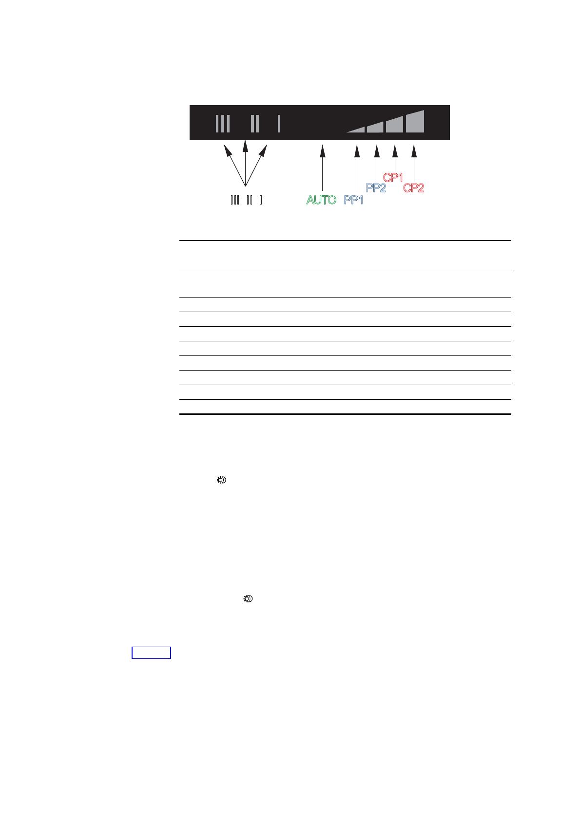
The pump setting is indicated by eight different light fields. See fig. 8.
Fig. 8 Eight light fields
See 11. Pump settings and pump performance for information about the
function of the settings.
6.4 Light field indicating the status of Automatic Night SetBack
Light in , see fig. 7, pos. 3, shows that Automatic Night SetBack is
active.
See 6.5 Push-button for activation of Automatic Night SetBack.
6.5 Push-button for activation of Automatic Night SetBack
The push-button, see fig. 7, pos. 4, activates/deactivates Automatic Night
SetBack.
Automatic Night SetBack is only relevant for heating systems prepared for
this function. See 8. Automatic Night SetBack.
The light field , see fig. 7, pos. 3, is on when Automatic Night SetBack is
active.
Factory setting: Automatic Night SetBack = not active.
6.6 Push-button for selection of pump setting
Every time the push-button is pressed, see fig. 7, pos. 5, the pump setting
is changed.
A cycle is eight button presses. See 6.3 Light fields indicating the pump
setting.
TM03 8926 2707
Button
presses
Light field Description
0
AUTO
ADAPT
(factory setting)
AUTO
ADAPT
1 PP1 Lowest proportional-pressure curve
2 PP2 Highest proportional-pressure curve
3 CP1 Lowest constant-pressure curve
4 CP2 Highest constant-pressure curve
5 III Constant curve, speed III
6 II Constant curve, speed II
7 I Constant curve, speed I
8AUTO
ADAPT AUTOADAPT
AUTO
ADAPT
III II I AUTO PP1
PP2 CP2
CP1
Note
If the pump has been set to speed I, II or III, it is not possible to select
Automatic Night SetBack.
14
7. Setting the pump
Contents:
7.1 Pump setting for system type
7.2 Pump control.
7.1 Pump setting for system type
Fig. 9 Selection of pump setting for system type
Factory setting = AUTO
ADAPT.
Recommended and alternative pump settings according to fig. 9:
AUTO
ADAPT (underfloor heating and two-pipe systems)
The AUTO
ADAPT function adjusts the pump performance to the actual
heat demand in the system. As the performance is adjusted gradually, it is
recommended to leave the pump in the AUTO
ADAPT position at least one
week before changing the pump setting.
If you choose to change back to AUTO
ADAPT, the pump remembers its
last setpoint in AUTO
ADAPT and resumes the automatic adjustment of the
performance.
TM03 8927 2707
A
B
C
Pos. System type
Pump setting
Recommended Alternative
A Underfloor heating AUTO
ADAPT*
Highest constant-pressure curve
(CP2)* or
lowest constant-pressure curve
(CP1)*
B Two-pipe systems AUTO
ADAPT*
Highest proportional-pressure
curve (PP2)*
C One-pipe systems
Lowest proportional-pressure
curve (PP1)*
Highest proportional-pressure
curve (PP2)*
* See 14.1 Guide to performance curves.
15
Changing from recommended to alternative pump setting
Heating systems are "slow" systems that cannot be set to the optimum
operation within minutes or hours.
If the recommended pump setting does not give the desired distribution of
heat in the rooms of the house, change the pump setting to the shown
alternative.
Explanation to pump settings in relation to performance curves,
see 11. Pump settings and pump performance.
7.2 Pump control
During operation, the pump head will be controlled according to the
principle "proportional-pressure control" (PP) or "constant-pressure
control" (CP).
In these control modes, the pump performance and consequently the
power consumption are adjusted according to the heat demand in the
system.
Proportional-pressure control
In this control mode, the differential pressure across the pump is
controlled according to the flow.
The proportional-pressure curves are indicated by PP1 and PP2 in the
Q/H diagrams. See 11. Pump settings and pump performance.
Constant-pressure control
In this control mode, a constant differential pressure across the pump is
maintained, irrespective of the flow.
The constant-pressure curves are indicated by CP1 and CP2 and are
the horizontal performance curves in the Q/H diagrams. See 11. Pump
settings and pump performance.
16
8. Automatic Night SetBack
Contents:
8.1 Basis for Automatic Night SetBack
8.2 Function of Automatic Night SetBack.
8.1 Basis for Automatic Night SetBack
Fig. 10 Automatic Night SetBack
TM03 8929 2707
Warning
Pumps built into gas boilers with a small water content must never
be set to Automatic Night SetBack.
Note
If speed I, II or III is selected, the Automatic Night SetBack is
deactivated.
Note
It is not necessary to reactivate Automatic Night SetBack if the
electricity supply has been switched off.
If the electricity supply is switched off when the pump is running on
the curve for Automatic Night SetBack, the pump will start in normal
operation. See 11. Pump settings and pump performance.
The pump changes back to the curve for Automatic Night SetBack
when the condition for Automatic Night SetBack is fulfilled again.
See 8.2 Function of Automatic Night SetBack.
Note
If the heating system is "undersupplied" (insufficient heat), check
whether Automatic Night SetBack is activated. If yes, deactivate this
function.
17
To ensure the optimum function of Automatic Night SetBack, the following
conditions must be fulfilled:
The pump must be installed in the flow pipe.
The Automatic Night SetBack function does not work if the pump is
installed in the return pipe.
The system (boiler) must incorporate automatic control of the liquid
temperature.
Activate Automatic Night SetBack by pressing .
See 6.5 Push-button for activation of Automatic Night SetBack.
Light in shows that Automatic Night SetBack is active.
18
8.2 Function of Automatic Night SetBack
Once Automatic Night SetBack has been activated, the pump changes
automatically between normal duty and night setback. See 11. Pump
settings and pump performance.
Changeover between normal duty and night setback is dependent on the
flow-pipe temperature.
The pump automatically changes over to night setback when a flow-pipe
temperature drop of more than 10-15 °C within approx. 2 hours is
registered. The temperature drop must be at least 0.1 °C/min.
Changeover to normal duty takes place without a time lag when the flow-
pipe temperature has increased by approx. 10 °C.
19
9. Systems with bypass valve between flow and return pipes
Contents:
9.1 Purpose of bypass valve
9.2 Manually operated bypass valve
9.3 Automatic bypass valve (thermostatically controlled).
9.1 Purpose of bypass valve
Fig. 11 Systems with bypass valve
Bypass valve
The purpose of the bypass valve is to ensure that the heat from the boiler
can be distributed when all valves in the underfloor-heating circuits and/or
thermostatic radiator valves are closed.
System elements:
bypass valve
flowmeter, pos. A.
The minimum flow must be present when all valves are closed.
The pump setting depends on the type of bypass valve used, i.e. manually
operated or thermostatically controlled.
9.2 Manually operated bypass valve
Follow this procedure:
1. Adjust the bypass valve with the pump in setting I (speed I).
The minimum flow (Q
min.
) for the system must always be observed.
Consult the manufacturer's instructions.
2. When the bypass valve has been adjusted, set the pump according to
7. Setting the pump.
TM03 8928 2707
A
20
9.3 Automatic bypass valve (thermostatically controlled)
Follow this procedure:
1. Adjust the bypass valve with the pump in setting I (speed I).
The minimum flow (Q
min.
) for the system must always be observed.
Consult the manufacturer's instructions.
2. When the bypass valve has been adjusted, set the pump to the lowest
or highest constant-pressure curve.
Explanation to pump settings in relation to performance curves, see
11. Pump settings and pump performance.
1 / 1

Grundfos alpha2 l Installation And Operating Instructions Manual

Type
Installation And Operating Instructions Manual

The Grundfos Alpha2 L is an energy-efficient circulator pump designed for heating systems and domestic hot water systems. It features automatic flow adaptation, allowing it to adjust its performance to the actual system requirements. The pump has a user-friendly control panel with a display showing the actual power consumption and eight light fields indicating the pump setting. The Grundfos Alpha2 L is easy to install and operate, making it an ideal choice for homeowners looking to improve the efficiency of their heating system.

Ask a question and I''ll find the answer in the document

Finding information in a document is now easier with AI

Ask the document