Supermicro 5018D-MF User manual
- Category
- Server barebones
- Type
- User manual
This manual is also suitable for

SUPERSERVER
5018D-MF
SUPER
®
USER’S MANUAL
1.0

The information in this User’s Manual has been carefully reviewed and is believed to be accurate.
The vendor assumes no responsibility for any inaccuracies that may be contained in this document,
makes no commitment to update or to keep current the information in this manual, or to notify any
person or organization of the updates. Please Note: For the most up-to-date version of this
manual, please see our web site at www.supermicro.com.
Super Micro Computer, Inc. ("Supermicro") reserves the right to make changes to the product
described in this manual at any time and without notice. This product, including software and docu-
mentation, is the property of Supermicro and/or its licensors, and is supplied only under a license.
Any use or reproduction of this product is not allowed, except as expressly permitted by the terms
of said license.
IN NO EVENT WILL SUPERMICRO BE LIABLE FOR DIRECT, INDIRECT, SPECIAL, INCIDENTAL,
SPECULATIVE OR CONSEQUENTIAL DAMAGES ARISING FROM THE USE OR INABILITY TO
USE THIS PRODUCT OR DOCUMENTATION, EVEN IF ADVISED OF THE POSSIBILITY OF
SUCH DAMAGES. IN PARTICULAR, SUPERMICRO SHALL NOT HAVE LIABILITY FOR ANY
HARDWARE, SOFTWARE, OR DATA STORED OR USED WITH THE PRODUCT, INCLUDING THE
COSTS OF REPAIRING, REPLACING, INTEGRATING, INSTALLING OR RECOVERING SUCH
HARDWARE, SOFTWARE, OR DATA.
Any disputes arising between manufacturer and customer shall be governed by the laws of Santa
Clara County in the State of California, USA. The State of California, County of Santa Clara shall
be the exclusive venue for the resolution of any such disputes. Super Micro's total liability for all
claims will not exceed the price paid for the hardware product.
FCC Statement: This equipment has been tested and found to comply with the limits for a Class A
digital device pursuant to Part 15 of the FCC Rules. These limits are designed to provide reasonable
protection against harmful interference when the equipment is operated in a commercial environ-
ment. This equipment generates, uses, and can radiate radio frequency energy and, if not installed
and used in accordance with the manufacturer’s instruction manual, may cause harmful interference
with radio communications. Operation of this equipment in a residential area is likely to cause harmful
interference, in which case you will be required to correct the interference at your own expense.
California Best Management Practices Regulations for Perchlorate Materials: This Perchlorate warn-
ing applies only to products containing CR (Manganese Dioxide) Lithium coin cells. “Perchlorate
Material-special handling may apply. See www.dtsc.ca.gov/hazardouswaste/perchlorate”
WARNING: Handling of lead solder materials used in this
product may expose you to lead, a chemical known to the
State of California to cause birth defects and other repro-
ductive harm.
Manual Revision 1.0
Release Date: June 25, 2013
Unless you request and receive written permission from Super Micro Computer, Inc., you may not
copy any part of this document.
Information in this document is subject to change without notice. Other products and companies
referred to herein are trademarks or registered trademarks of their respective companies or mark
holders.
Copyright © 2013 by Super Micro Computer, Inc.
All rights reserved.
Printed in the United States of America

iii
Preface
Preface
About This Manual
This manual is written for professional system integrators and PC technicians. It
provides information for the installation and use of the SuperServer 5018D-MF.
Installation and maintenance should be performed by experienced technicians only.
The SuperServer 5018D-MF is a high-end server based on the SC512F-350B 1U
rackmount chassis and the Super X10SLL-F single processor motherboard.
Manual Organization
Chapter 1: Introduction
The fi rst chapter provides a checklist of the main components included with the
server system and describes the main features of the X10SLL-F motherboard and
the SC512F-350B chassis.
Chapter 2: Server Installation
This chapter describes the steps necessary to install the SuperServer 5018D-MF
into a rack and check out the server confi guration prior to powering up the system.
If your server was ordered without processor and memory components, this chapter
will refer you to the appropriate sections of the manual for their installation.
Chapter 3: System Interface
Refer here for details on the system interface, which includes the functions and
information provided by the control panel on the chassis as well as other LEDs
located throughout the system.

SUPERSERVER 5018D-MF User's Manual
iv
Chapter 4: Standardized Warning Statements
You should thoroughly familiarize yourself with this chapter for a general overview
of safety precautions that should be followed when installing and servicing the
SuperServer 5018D-MF.
Chapter 5: Advanced Motherboard Setup
Chapter 5 provides detailed information on the X10SLL-F motherboard, including the
locations and functions of connections, headers and jumpers. Refer to this chapter
when adding or removing processors or main memory and when reconfi guring the
motherboard.
Chapter 6: Advanced Chassis Setup
Refer to Chapter 6 for detailed information on the SC512F-350B server chassis.
You should follow the procedures given in this chapter when installing, removing or
reconfi guring SATA or peripheral drives and when replacing system power supply
modules and cooling fans.
Chapter 7: BIOS
The BIOS chapter includes an introduction to BIOS and provides detailed informa-
tion on running the CMOS Setup Utility.
Appendix A: BIOS Error Beep Codes
Appendix B: System Specifi cations

v
Preface
Notes

vi
Table of Contents
Chapter 1 Introduction
1-1 Overview .........................................................................................................1-1
1-2 Motherboard Features .....................................................................................1-2
Processors ......................................................................................................1-2
Memory ...........................................................................................................1-2
Serial ATA ........................................................................................................ 1-2
I/O Ports ..........................................................................................................1-2
1-3 Server Chassis Features ................................................................................1-3
Serial ATA Subsystem ..................................................................................... 1-3
Control Panel .................................................................................................. 1-3
Cooling System ............................................................................................... 1-3
1-4 Contacting Supermicro ....................................................................................1-5
Chapter 2 Server Installation
2-1 Overview .........................................................................................................2-1
2-2 Unpacking the System ....................................................................................2-1
2-3 Preparing for Setup .........................................................................................2-1
Choosing a Setup Location .............................................................................2-2
2-4 Warnings and Precautions .............................................................................. 2-2
Rack Precautions ............................................................................................ 2-2
Server Precautions ..........................................................................................2-2
Rack Mounting Considerations .......................................................................2-3
Ambient Operating Temperature ................................................................ 2-3
Reduced Airfl ow .........................................................................................2-3
Mechanical Loading ................................................................................... 2-3
Circuit Overloading .....................................................................................2-3
Reliable Ground ......................................................................................... 2-3
2-5 Installing the System into a Rack ................................................................... 2-4
Basic Installation Procedure ...........................................................................2-4
Installing with Rackmount Kit .......................................................................... 2-5
Chapter 3 System Interface
3-1 Overview .........................................................................................................3-1
3-2 Control Panel Buttons ..................................................................................... 3-1
Reset ...............................................................................................................3-1
Power ..............................................................................................................3-1
3-3 Control Panel LEDs ........................................................................................ 3-2
Overheat/Fan Fail ...........................................................................................3-2
SUPERSERVER 5018D-MF User's Manual

vii
Table of Contents
NIC2 ................................................................................................................3-2
NIC1 ................................................................................................................3-2
HDD .................................................................................................................3-3
Power ..............................................................................................................3-3
Chapter 4 Standardized Warning Statements for AC Systems
4-1 About Standardized Warning Statements ....................................................... 4-1
Warning Defi nition ...........................................................................................4-1
Installation Instructions ....................................................................................4-4
Circuit Breaker ................................................................................................ 4-5
Power Disconnection Warning ........................................................................4-6
Equipment Installation ..................................................................................... 4-8
Restricted Area ................................................................................................ 4-9
Battery Handling ............................................................................................4-10
Redundant Power Supplies ..........................................................................4-12
Backplane Voltage ........................................................................................4-13
Comply with Local and National Electrical Codes ........................................ 4-14
Product Disposal ........................................................................................... 4-15
Hot Swap Fan Warning ................................................................................. 4-16
Power Cable and AC Adapter ...................................................................... 4-18
Chapter 5 Advanced Motherboard Setup
5-1 Handling the Motherboard ..............................................................................5-1
Precautions .....................................................................................................5-1
Unpacking .......................................................................................................5-1
5-2 Processor and Heatsink Installation................................................................5-2
Installing an LGA 1150 Processor ................................................................... 5-2
Installing a Passive CPU Heatsink ................................................................. 5-4
Removing the Heatsink ................................................................................... 5-4
5-3 Connecting Cables ..........................................................................................5-7
Connecting Data Cables .................................................................................5-7
Connecting Power Cables ..............................................................................5-7
Connecting the Control Panel ......................................................................... 5-7
5-4 I/O Ports ..........................................................................................................5-8
5-5 Installing Memory ............................................................................................ 5-9
5-6 Adding PCI Cards .........................................................................................5-12
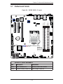
5-7 Motherboard Details ......................................................................................5-13
X10SLL-F Quick Reference ..........................................................................5-13
5-8 Connector Defi nitions ................................................................................... 5-15
5-9 Jumper Settings ............................................................................................5-21

viii
SUPERSERVER 5018D-MF User's Manual
5-10 Onboard Indicators ........................................................................................5-24
5-11 SATA Drive Connections ............................................................................... 5-25
5-12 Installing Software .........................................................................................5-26
SuperDoctor III .............................................................................................. 5-27
5-13 Onboard Battery ............................................................................................ 5-28
Chapter 6 Advanced Chassis Setup
6-1 Static-Sensitive Devices ..................................................................................6-1
Precautions .....................................................................................................6-1
6-2 Control Panel ..................................................................................................6-2
6-3 System Fans ...................................................................................................6-3
System Fan Failure ......................................................................................... 6-3
6-4 Drive Bay Installation/Removal .......................................................................6-4
Accessing the Drive Bays ...............................................................................6-4
DVD-ROM Drive Installation ........................................................................... 6-5
6-5 Power Supply .................................................................................................. 6-7
Power Supply Failure ......................................................................................6-7
Chapter 7 BIOS
7-1 Introduction ...................................................................................................... 7-1
Starting BIOS Setup Utility ..............................................................................7-1
How To Change the Confi guration Data ......................................................... 7-1
How to Start the Setup Utility .........................................................................7-2
7-2 Main Setup ...................................................................................................... 7-2
7-3 Advanced Setup Confi gurations......................................................................7-4
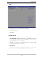
7-4 Event Logs ....................................................................................................7-23
7-5 Boot Settings .................................................................................................7-27
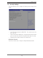
7-6 Security Settings ...........................................................................................7-29
7-7 Save & Exit ................................................................................................... 7-30
Appendix A BIOS Error Beep Codes
Appendix B System Specifi cations

Chapter 1
Introduction
1-1 Overview
The SuperServer 5018D-MF is a high-end server comprised of two main subsys-
tems: the SC512F-350B 1U server chassis and the X10SLL-F single processor
motherboard. Please refer to our web site for information on operating systems that
have been certifi ed for use with the system (www.supermicro.com).
In addition to the motherboard and chassis, various hardware components have
been included with the 5018D-MF, as listed below:
• Two sets of 4-cm counter-rotating fans (FAN-0087L4)
• One passive CPU heatsink (SNK-P0046P)
• One riser card for one PCI-E 3.0 x8 PCI add-on card in a PCI-E 3.0 x16 slot
(RSC-RR1U-E16)
Chapter 1: Introduction
1-1

1-2
SUPERSERVER 5018D-MF User's Manual
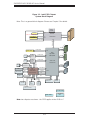
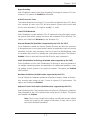
1-2 Motherboard Features
At the heart of the SuperServer 5018D-MF lies the X10SLL-F, a single processor
motherboard based on the Intel® C222 chipset. Below are the main features of the
X10SLL-F (see Figure 1-1 for a block diagram of the chipset).
Processors
The X10SLL-F supports a single Intel
®
Core™ i7/i5/i3 DT or Intel® Xeon® E3-1200
v3 or Intel® Xeon® E3-1200 v3 processor in an LGA1150 socket. Please refer to
the motherboard description pages on our web site for a complete listing of sup-
ported processors.
Memory
The X10SLL-F has four DIMM sockets that can support up to 32 GB of Unbuffered
ECC/non-ECC DDR3-1600/1333 memory. Please refer to Chapter 5 for installing
memory.
Serial ATA
An on-chip SATA controller is integrated into the X10SLL-F to provide two 6 Gb/sec
SATA 3.0 ports and four 3 Gb/sec SATA 2.0 ports.
I/O Ports
The rear I/O ports include one COM port, a VGA (monitor) port, four USB 2.0 ports,
and two gigabit Ethernet ports. A dedicated IPMI LAN port is also included.

1-3
Chapter 1: Introduction
1-3 Server Chassis Features
The SC512F-350B is a short depth (14.5") 1U rackmount server chassis. The fol-
lowing is a general outline of the main features of the SC512F-350B chassis.
System Power
When confi gured as the SuperServer 5018D-MF, the SC512F-350B chassis features
a single power supply.
Serial ATA Subsystem
The SC512F-350B chassis is designed to support one internal SATA hard drive.
The internal drive is not hot-swappable.
Control Panel
The SC512F-350B's control panel provides important system monitoring and con-
trol information. LEDs indicate power on, network activity, hard disk drive activity,
overheat warning and fan failure. The control panel also includes a main power
button and a reset button.
Cooling System
The SC512F-350B chassis has an innovative cooling design that features two 4-cm
counter-rotating fans with fan speed controlled by IPMI.

1-4
SUPERSERVER 5018D-MF User's Manual
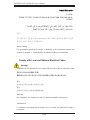
Figure 1-1. Intel C222 Chipset:
System Block Diagram
Note: This is a general block diagram. Please see Chapter 5 for details.
3 PHASE
VR12.5
#B-0
#B-1
Haswell-DT
4 CORE DDR-III
DMI
PCI-E X16 G3
PCI-E x16
PCI-E X8 G3
PCI-E x8(x16)
PCI-E x8
BOM Select (Default: 2 *8)
DMI x4 G2
#5/6/7/8
PCH
Lynx Point
C222 / C224
6.0 Gb/S
USB 2.0
LPC
#1
#0
SATA
PCI-E X4 G2
3.0 Gb/S
#5
#4
#3
#2
SATA
TPM HEADER
USB 3.0
PCI-E x4(x8)
BIOS
HEADER
SPI
LAN2
Clarkville
i217LM
PCI-E X1 G2
RJ45
LAN1
Springville
i210AT
PCI-E X1 G2
RJ45
AST2400 / 1400
BMC
#3
#2
#1
RMII/NCSI
COM1
Connector
COM2
Header
VGA CONN
BMC Boot Flash
DDR3
SPI
LAN3
RGRMII
Debug Card
FRONT PANEL
SYSTEM POWER
CTRL
FAN SPEED
PCI-E X1 G2
USB 2.0
#2 USB2.0
#0-15
#0-7
#8-15
RTL8211E-VB-CG
RJ45
X10SLx: AST1400
X10SLx-F: AST2400
X10SLL: C222
X10SLM: C224
BIOS
SPI
SPI
Temp Sensor
EMC1402-1 *2 at diff SMBUS
up to 1600
#A-1
DDRIII
#A-0
USBUSB
Note: two chipsets are shown - the C222 applies to the X10SLL-F.

1-5
Chapter 1: Introduction
1-4 Contacting Supermicro
Headquarters
Address: Super Micro Computer, Inc.
980 Rock Ave.
San Jose, CA 95131 U.S.A.
Tel: +1 (408) 503-8000
Fax: +1 (408) 503-8008
Email: [email protected] (General Information)
[email protected] (Technical Support)
Web Site:
www.supermicro.com
Europe
Address: Super Micro Computer B.V.
Het Sterrenbeeld 28, 5215 ML
's-Hertogenbosch, The Netherlands
Tel: +31 (0) 73-6400390
Fax: +31 (0) 73-6416525
Email: [email protected] (General Information)
[email protected] (Technical Support)
[email protected] (Customer Support)
Asia-Pacifi c
Address: Super Micro Computer, Inc.
3F, No. 150, Jian 1st Rd.
Zhonghe Dist., New Taipei City 23511
Taiwan (R.O.C)
Tel: +886-(2) 8226-3990
Fax: +886-(2) 8226-3992
Web Site:
www.supermicro.com.tw
Technical Support:
Email: [email protected]
Tel: +886-(2)-8226-3990

1-6
SUPERSERVER 5018D-MF User's Manual
Notes

Chapter 2: Server Installation
2-1
Chapter 2
Server Installation
2-1 Overview
This chapter provides a quick setup checklist to get your SuperServer 5018D-MF
up and running. Following the steps in the order given should enable you to have
the system operational within a minimal amount of time. This quick setup assumes
that your system has come to you with the processor and memory preinstalled. If
your system is not already fully integrated with a motherboard, processor, system
memory etc., please turn to the chapter or section noted in each step for details on
installing specifi c components.
2-2 Unpacking the System
You should inspect the box the server was shipped in and note if it was damaged
in any way. If the server itself shows damage, you should fi le a damage claim with
the carrier who delivered it.
Decide on a suitable location for the rack unit that will hold the server. It should
be situated in a clean, dust-free area that is well ventilated. Avoid areas where
heat, electrical noise and electromagnetic fi elds are generated. You will also need
it placed near a grounded power outlet. Read the Rack and Server Precautions in
the next section.
2-3 Preparing for Setup
The SuperServer 5018D-MF does not ship with a rack rail hardware package as
the system can be rack mounted without the use of rails. An optional rack rail
package is available if you wish to order from Supermicro. Follow the steps in the
order given to complete the installation process in a minimal amount of time. Please
read this section in its entirety before you begin the installation procedure outlined
in the sections that follow.

2-2
SUPERSERVER 5018D-MF User's Manual
Choosing a Setup Location
• Leave enough clearance in front of the rack to enable you to open the front door
completely (~25 inches) and approximately 30 inches of clearance in the back
of the rack to allow for suffi cient airfl ow and ease in servicing.This product is for
installation only in a Restricted Access Location (dedicated equipment rooms,
service closets and the like).
• This product is not suitable for use with visual display work place devices
acccording to §2 of the the German Ordinance for Work with Visual Display Units.
2-4 Warnings and Precautions
Rack Precautions
• Ensure that the leveling jacks on the bottom of the rack are fully extended to
the fl oor with the full weight of the rack resting on them.
• In single rack installation, stabilizers should be attached to the rack. In multiple
rack installations, the racks should be coupled together.
• Always make sure the rack is stable before extending a component from the
rack.
• You should extend only one component at a time - extending two or more si-
multaneously may cause the rack to become unstable.
Server Precautions
• Review the electrical and general safety precautions in Chapter 4.
• Determine the placement of each component in the rack before you install the
rails.
• Install the heaviest server components on the bottom of the rack fi rst, and then
work up.
• Use a regulating uninterruptible power supply (UPS) to protect the server from
power surges, voltage spikes and to keep your system operating in case of a
power failure.
• Allow the hot plug SATA drives and power supply modules to cool before touch-
ing them.

Chapter 2: Server Installation
2-3
• Always keep the rack's front door and all panels and components on the servers
closed when not servicing to maintain proper cooling.
Rack Mounting Considerations
Ambient Operating Temperature
If installed in a closed or multi-unit rack assembly, the ambient operating tempera-
ture of the rack environment may be greater than the ambient temperature of the
room. Therefore, consideration should be given to installing the equipment in an
environment compatible with the manufacturer’s maximum rated ambient tempera-
ture (Tmra).
Reduced Airfl ow
Equipment should be mounted into a rack so that the amount of airfl ow required
for safe operation is not compromised.
Mechanical Loading
Equipment should be mounted into a rack so that a hazardous condition does not
arise due to uneven mechanical loading.
Circuit Overloading
Consideration should be given to the connection of the equipment to the power
supply circuitry and the effect that any possible overloading of circuits might have
on overcurrent protection and power supply wiring. Appropriate consideration of
equipment nameplate ratings should be used when addressing this concern.
Reliable Ground
A reliable ground must be maintained at all times. To ensure this, the rack itself
should be grounded. Particular attention should be given to power supply connec-
tions other than the direct connections to the branch circuit (i.e. the use of power
strips, etc.).

2-4
SUPERSERVER 5018D-MF User's Manual
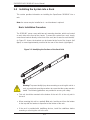
2-5 Installing the System into a Rack
This section provides information on installing the SuperServer 5018D-MF into a
rack.
Note: the server may be installed as is - rack hardware is optional.
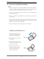
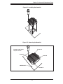
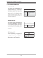
Basic Installation Procedure
The 5018D-MF server comes with two rack mounting brackets, which are located
on each side at the front of the chassis. To mount the system into a rack, simply
screw these brackets directly to the front of the rack (two screws for each bracket).
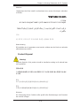
As Figure 2-1 shows, the brackets can be located at the front of the chassis (left
fi gure) or moved approximately one-third to the rear of the chassis (right fi gure).
Figure 2-1. Identifying the Sections of the Rack Rails
Warning! To prevent bodily injury when mounting or servicing this unit in a
rack, you must take special precautions to ensure that the system remains
stable. The following guidelines are provided to ensure your safety:
• This unit should be mounted at the bottom of the rack if it is the only unit in
the rack.
• When mounting this unit in a partially fi lled rack, load the rack from the bottom
to the top with the heaviest component at the bottom of the rack.
• If the rack is provided with stabilizing devices, install the stabilizers before
mounting or servicing the unit in the rack.

Chapter 2: Server Installation
2-5
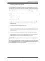
Installing with Rackmount Kit
This is a guideline for installing the unit into a rack with the optional rack kit (MCP-
290-00004-03). You should also refer to the installation instructions that came with
the rack unit you are using. Be aware that there are a variety of rack units on the
market, which may mean the assembly procedure will differ slightly.
The rack hardware includes two assemblies that consists of two sections: an inner
rail that secures to the chassis and an outer rail that secures directly to the rack
itself (see Figure 2-1).
Installing the Chassis Rails
1. Detach the two rail sections from each other by depressing the locking tab
on the inner rail to release it from its locked position, then pull the two rails
completely apart.
2. Repeat step 1 for the remaining rail assembly.
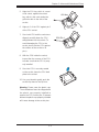
3. Position the fi xed chassis rail sections you just removed along the side of the
chassis making sure the three screw holes line up. Note that the rails are left/
right side specifi c.
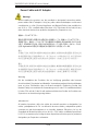
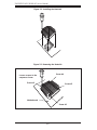
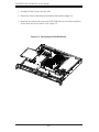
4. Screw the rail securely to the side of the chassis (see Figure 2-2). Repeat
this procedure for the other rail on the other side of the chassis. You will also
need to attach the rail brackets when installing into a telco rack.
Locking Tabs: Both chassis rails have a locking tab, which serves two functions.
The fi rst is to lock the server into place when installed and pushed fully into the
rack, which is its normal position. Secondly, these tabs also lock the server in place
when fully extended from the rack. This prevents the server from coming completely
out of the rack when you pull it out for servicing.

2-6
SUPERSERVER 5018D-MF User's Manual
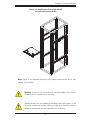
Installing the Rack Rails
1. Determine where you want to place the 5018D-MF in the rack (see Rack and
Server Precautions in Section 2-3).
2. Position the fi xed rack rail/sliding rail guide assemblies at the desired location
in the rack, keeping the sliding rail guide facing the inside of the rack.
3. Screw the assembly securely to the rack using the brackets provided.
4. Attach the other assembly to the other side of the rack, making sure that both
are at the exact same height and with the rail guides facing inward.
Installing the Server into the Rack
You should now have rails attached to both the chassis and the rack unit. The next
step is to install the server into the rack.
1. Line up the rear of the chassis rails with the front of the rack rails.
2. Slide the chassis rails into the rack rails, keeping the pressure even on both
sides (you may have to depress the locking tabs when inserting). See Figure
2-3.
3. When the server has been pushed completely into the rack, you should hear
the locking tabs "click".
4. Finish by inserting and tightening the thumbscrews that hold the front of the
server to the rack.
Figure 2-2. Installing Chassis Rails
Page is loading ...
Page is loading ...
Page is loading ...
Page is loading ...
Page is loading ...
Page is loading ...
Page is loading ...
Page is loading ...
Page is loading ...
Page is loading ...
Page is loading ...
Page is loading ...
Page is loading ...
Page is loading ...
Page is loading ...
Page is loading ...
Page is loading ...
Page is loading ...
Page is loading ...
Page is loading ...
Page is loading ...
Page is loading ...
Page is loading ...
Page is loading ...
Page is loading ...
Page is loading ...
Page is loading ...
Page is loading ...
Page is loading ...
Page is loading ...
Page is loading ...
Page is loading ...
Page is loading ...
Page is loading ...
Page is loading ...
Page is loading ...
Page is loading ...
Page is loading ...
Page is loading ...
Page is loading ...
Page is loading ...
Page is loading ...
Page is loading ...
Page is loading ...
Page is loading ...
Page is loading ...
Page is loading ...
Page is loading ...
Page is loading ...
Page is loading ...
Page is loading ...
Page is loading ...
Page is loading ...
Page is loading ...
Page is loading ...
Page is loading ...
Page is loading ...
Page is loading ...
Page is loading ...
Page is loading ...
Page is loading ...
Page is loading ...
Page is loading ...
Page is loading ...
Page is loading ...
Page is loading ...
Page is loading ...
Page is loading ...
Page is loading ...
Page is loading ...
Page is loading ...
Page is loading ...
Page is loading ...
Page is loading ...
Page is loading ...
Page is loading ...
Page is loading ...
Page is loading ...
Page is loading ...
Page is loading ...
Page is loading ...
Page is loading ...
Page is loading ...
Page is loading ...
Page is loading ...
Page is loading ...
Page is loading ...
Page is loading ...
Page is loading ...
Page is loading ...
Page is loading ...
Page is loading ...
Page is loading ...
Page is loading ...
Page is loading ...
Page is loading ...
Page is loading ...
Page is loading ...
Page is loading ...
Page is loading ...
-
 1
1
-
 2
2
-
 3
3
-
 4
4
-
 5
5
-
 6
6
-
 7
7
-
 8
8
-
 9
9
-
 10
10
-
 11
11
-
 12
12
-
 13
13
-
 14
14
-
 15
15
-
 16
16
-
 17
17
-
 18
18
-
 19
19
-
 20
20
-
 21
21
-
 22
22
-
 23
23
-
 24
24
-
 25
25
-
 26
26
-
 27
27
-
 28
28
-
 29
29
-
 30
30
-
 31
31
-
 32
32
-
 33
33
-
 34
34
-
 35
35
-
 36
36
-
 37
37
-
 38
38
-
 39
39
-
 40
40
-
 41
41
-
 42
42
-
 43
43
-
 44
44
-
 45
45
-
 46
46
-
 47
47
-
 48
48
-
 49
49
-
 50
50
-
 51
51
-
 52
52
-
 53
53
-
 54
54
-
 55
55
-
 56
56
-
 57
57
-
 58
58
-
 59
59
-
 60
60
-
 61
61
-
 62
62
-
 63
63
-
 64
64
-
 65
65
-
 66
66
-
 67
67
-
 68
68
-
 69
69
-
 70
70
-
 71
71
-
 72
72
-
 73
73
-
 74
74
-
 75
75
-
 76
76
-
 77
77
-
 78
78
-
 79
79
-
 80
80
-
 81
81
-
 82
82
-
 83
83
-
 84
84
-
 85
85
-
 86
86
-
 87
87
-
 88
88
-
 89
89
-
 90
90
-
 91
91
-
 92
92
-
 93
93
-
 94
94
-
 95
95
-
 96
96
-
 97
97
-
 98
98
-
 99
99
-
 100
100
-
 101
101
-
 102
102
-
 103
103
-
 104
104
-
 105
105
-
 106
106
-
 107
107
-
 108
108
-
 109
109
-
 110
110
-
 111
111
-
 112
112
-
 113
113
-
 114
114
-
 115
115
-
 116
116
-
 117
117
-
 118
118
-
 119
119
-
 120
120


Supermicro 5018D-MF User manual
- Category
- Server barebones
- Type
- User manual
- This manual is also suitable for
Ask a question and I''ll find the answer in the document
Finding information in a document is now easier with AI
Related papers
-
Supermicro SUPERSERVER 5018D-FN8T User manual
-
Super X10SLL-F User manual
-
-
Supermicro SUPERSERVER 5018D-MTLN4F User manual
-
-
Supermicro 5038D-I User manual
-
 Super X10SLX-F User manual
-
Supermicro X10SLL+-F User manual
-
-
