15
> Before start > Hookup > Setup > Playback > Part Names > Advanced Manual
Troubleshooting | Appendix
OR
1
23
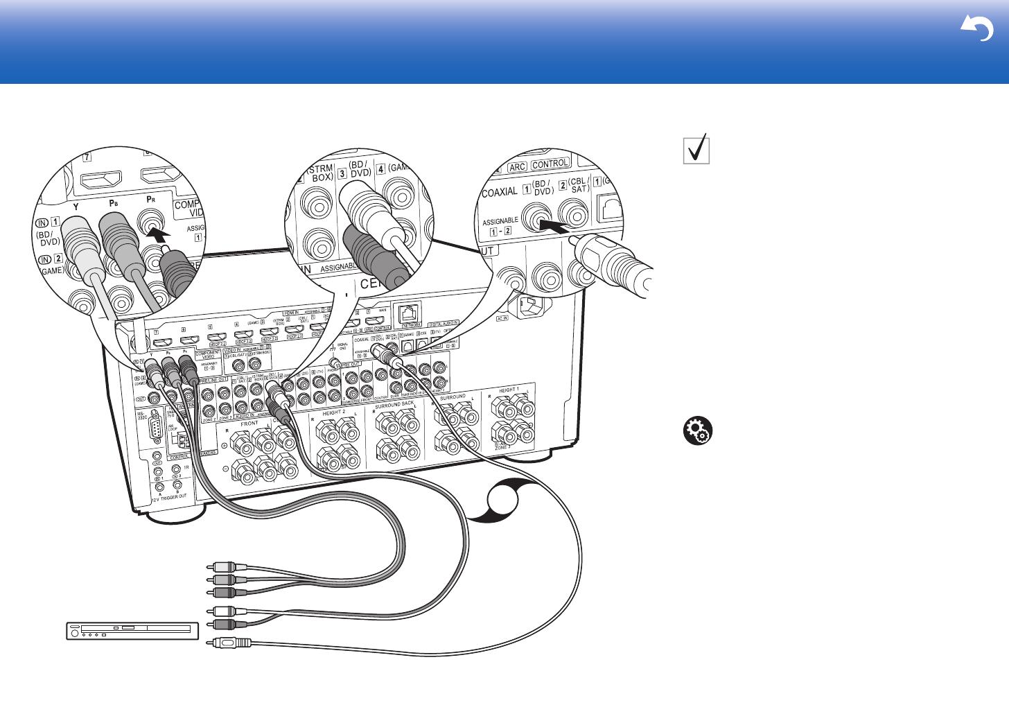
BD/DVD
1 Component video cable, 2 Digital coaxial cable, 3 Analog audio cable
Non-HDMI AV Components
This is an example of connection with an AV component
that does not have an HDMI jack. Make the connections
to the AV component to match the jacks it has. When
video input connection is to the BD/DVD jack, the audio
input connection should also be to the BD/DVD jacks, and
so on, so that you connect the video input jacks to the
jacks with the same name as the audio input jacks. Note
that video signals input to the VIDEO IN jack or the
COMPONENT VIDEO IN jacks will be converted to HDMI
video signals and then output from the HDMI OUT jack.
0 To enjoy digital surround playback in formats such as
Dolby Digital, you need to make a connection for audio
signals with a digital coaxial cable or digital optical
cable.
0 It is possible to change assignment of the input jacks
you see in the illustration at left, so you can also
connect to any jack other than BD/DVD. For details,
see the Advanced Manual.
Setup
0 The COMPONENT VIDEO IN jacks are
compatible only with 480i or 576i resolution. When
you input video signals to the COMPONENT
VIDEO IN jacks, set the output resolution of the
player to 480i or 576i. Select interlace if there is no
option for 480i, etc. If your player does not support
480i or 576i output, use the VIDEO IN jack.
0 To enjoy digital surround sound including Dolby
Digital, audio output should be set to "Bitstream
output" on the connected Blu-ray Disc Player or
other device.


