Broan 433004 Owner's manual

Category
Cooker hoods
Type
Owner's manual

This manual is also suitable for

A GE
IE
HOOD
To register this
product visit
www.broan.com
iNTENDED FOR DOMESTIC COOKING ONLY
WARNING
TO REDUCETHE RiSK OF FIRE, ELECTRIC SHOCK, OR iNJURY
TO PERSONS, OBSERVE THE FOLLOWING:
1. Use this unit only in the manner intended by the manufacturer, tf
you have questions, contact the manufacturer at the address or
telephone number listed in the warranty.
2. Before servicing or cleaning unit, switch power off at service panel
and lock service panel to prevent power from being switched on
accidentally. When the service disconnecting means cannot be
locked, securely fasten a prominent warning device, such as a
tag, to the service panel.
3. Installation work and electrical wiring must be done by a quali-
fied person(s) in accordance with all applicable codes and stan-
dards.
4. Sufficient air is needed for proper combustion and exhausting of
gases through the flue (chimney) of fuel burning equipment to
prevent backdrafting. Follow the heating equipment manufacturer's
guideline and safety standards such as those published by the
National Fire Protection Association (NFPA), and the American
Society for Heating, Refrigeration and Air Conditioning Engineers
(ASHRAE), and the local code authorities.
5. When cutting or drilling into wall or ceiling, do not damage electri-
cal wiring and other hidden utilities.
6. Ducted fans must always be vented to the outdoors.
7. Do not use this unit with any solid-state speed control device.
8. To reduce the risk of fire, use only metal ductwork.
9. Use with approved cord-connection kit only.
10.This unit must be grounded.
TO REDUCETHE RiSK OF A RANGETOP GREASE FIRE:
1. Never leave surface units unattended at high settings. Boilovers
cause smoking and greasy spillovers that may ignite. Heat oils
slowly on low or medium settings.
2. Always turn hood ON when cooking at high heat or when cooking
flaming foods.
3. Clean ventilating fans frequently. Grease should not be allowed
to accumulate on fan or filter.
4. Use proper pan size. Always use cookware appropriate for the
size of the surface element.
TO REDUCETHE RISK OF INJURYTO PERSONS INTHE EVENT
OF A RANGE TOP GREASE FIRE, OBSERVE THE FOLLOW-
iNG:*
1. SMOTHER FLAMES with a close-fitting lid, cookie sheet, or
metal tray, then turn off the burner. BE CAREFUL TO PREVENT
BURNS. If the flames do not go out immediately, EVACUATE
AND CALL THE FiRE DEPARTMENT.
2. NEVER PICK UP A FLAMING PAN - You may be burned.
3. DO NOT USE WATER, including wet dishcloths or towels - a
violent steam explosion will result.
4. Use an extinguisher ONLY if:
A. You know you have a Class ABC extinguisher and you already
know how to operate it.
B. The fire is small and contained in the area where it started.
C. The fire department is being called.
D. You can fight the fire with your back to an exit.
*Based on "Kitchen Firesafety Tips" published by NFPA.
CAUTION
1. For general ventilating use only. Do not use to exhaust hazardous
or explosive materials and vapors.
2. To avoid motor bearing damage and noisy and/or unbalanced
impellers, keep drywall spray, construction dust, etc. off power
unit.
3. For best capture of cooking impurities, your range hood should
be mounted 18-25" above the cooking surface.
4. Please read specification label on product for further information
and requirements.
IMPORTANT: OBSERVE ALL GOVERNING CODES AND ORDI-
NANCES
Your range hood has been designed to filter out smoke, odors, and
grease which rise from the cooking surface. Before you being the
installation be sure that all parts and accessories are removed from
carton. For best results and ease in the installation of this range
hood, read the instructions sheet to become familiar with the step-
by-step installation.
TOOLS AND MATERIALS
REQUIRED
r3 Drill, electric or ratchet drive
[_ 1/8" drill bit for drilling pilot holes
[_ 1-1/4" wood bit for drilling electrical wiring access hole
[_ One common head screwdriver for securing hood mounting
screws to the cabinet and hood sheet metal parts
[_ Pliers for opening knockouts
[_ Pencil, rule and level for marking cabinet locations
[_ Saber saw or keyhole saw for cutting the wall or cabinet open-
ings
[_ Metal snips, duct tape, duct (with elbows and transition, if neces-
sary), roof cement or caulk, and roof or wall cap, as required
[_ Electrical wiring and supplies of type to comply with local codes
The following materials are required only for installation on recessed
bottom kitchen cabinets:
[_ Two 1" x 2" x 12" (approximate length) wood strips (purchase
locally)
[_ Four 1-1/4" long flat head wood screws (purchase locally)
INSTALLER:
LEAVE THIS MANUAL WITH THE
HOMEOWNER.
HOMEOWNER:
USE AND CARE iNSTRUCTiONS ON PAGE 4.
PREPARING THE HOOD
1. Unpack hood and check contents. You should receive:
1- Filter with built-in light lens
1- 3-1/4" x 10" damper/duct connector
1- Installation parts bag
LIGHTLENS _ /_--
tt _ _.ALUMINUMOR
cop#A ,O.
2. Remove junction box cover.
JUNCTION BOX
3. Remove top or rear electrical knockout.
4. Select one of the three types of venting available:
Non-Vented -- Remove vent cover from hood front. Replace
the aluminum filter with a non-ducted filter (BP57 or R610050
- purchase separately). Go to "Preparing the Installation Loca-
tion".
VENTC0VER
Rectangular Vented- 3-1/4" x 10" vertical or horizontal. Re-
move knockout #@ for vertical or knockout #(3)for horizontal
venting. Install damper/duct connector over opening. Go to
"Planning Ductwork Installation".
Round Vented --7" vertical. Remove knockouts #_i) and #@
exposing duct collar. Go to "Planning Ductwork Installation".
PLANNING DUCTWORK
INSTALLATION
This section for vented hoods only. Non-vented hoods skip
this section and go on to "Preparing the Installation Loca=
tion".
Begin planning ductwork by deciding where duct will run between
hood and outside. For best performance, use shortest possible
duct run and a minimum number of elbows. There are several
choices.
ROOF CAP
ROOF CAP _,.
BP87DAMPER NOT,N
CLUDED) LOCATED AT - ! I| II
LEAST 6" FROM HOOD I t I_._--VERTICAL--_, ii II
IN VERTICAL SECTION I I 7A!-
I
P :3V4"x IO"
RECTANGULAR
DAMPER
- (INCLUDED)
REMOVE THE
HOOD DAMPER
FLAP IF IT IN-
TERFERES WITH
THE WALL CAP
DAMPER
7" ROUND DUCT VENTING :3 I/4" x IO" RECTANGULAR VENTING
Ducting directly through the wall (for range hoods mounted
on an exterior wall). Shown are two ways to duct through an
outside wall. If a wall cap is used directly off the back of the
hood, special care must be taken to make sure that the damper
in the damper/duct connector on the hood and damper in the
wall cap do not interfere with each other when the hood is
operating. This could result in either inadequate air delivery
or back drafts. If this condition does exist, remove the hood
damper flap. Sometimes when using a wall cap, it is easier to
duct vertically and then use an elbow.
Ducting straight up through roof using 3-1/4" x 10" or 7" round
duct. For single story installations.
Ducting between ceiling joists for multi-story installations or
through soffits above cabinets where soffit connects to outside
walls.
PREPARING THE
INSTALLATION LOCATION
NOTE: MOUNT HOOD SO THAT BOTTOM OF HOOD IS 18"
TO 25" ABOVE COOKING SURFACE.TOP FRONT OF HOOD
SHOULD BE FLUSH WITH FRONT OF CABINET FRAME.
IF DISTANCE BETWEEN WALL AND FRONT OF CABINET
FRAME IS MORE THAN 12",THERE WiLL BE A SPACE BE-
TWEEN BACK OF HOOD ANDWALL.THIS IS NORMAL.
OMIT STEP 1 IF HOOD WILL BE INSTALLED UNDER CABI=
NETS WITH FLUSH BOTTOM.
\
3" \
\
\ "L_
FILLER STRIP \
1. For cabinets with recessed bottoms only: Install wood filler
strips on each side of recessed area under cabinet. Use two
1" x 2" strips cut to length (use thicker strips if necessary).
Fasten strips with wood screws about 3" in from each end.
2. Measure and mark the following:
a.) Electrical wiring opening in wall or cabinet.
b.) Duct opening in wall or cabinet (vented hoods only).
-- CABINETCUTOUTS
.... JZ_._ 3=1/4" x 10"
/A ,//_-W/\ RECTANGULAR
///_i VENTING
0.2 cm)
_ -_ ,5_Q _'m_ 11/2" (3-8 ca)
, ,,- or4 Lio.ouNU
'_- STARTER HOLES CABINET
//-CUTOUTS
7" ROUND _"_
VENTING
\ V _- STARTER HOLES (12.7 cm)
WARNING: WHEN CUTTING OR DRILLING INTO WALL OR
CABINET, BE CAREFUL NOT TO CUT EXISTING ELECTRI-
CALWIRING.
3. Drill 1-1/4" electrical wiring opening in wall or cabinet bot-
tom.
4. Drill four pilot holes in corners of marked duct opening and cut
opening with saber or keyhole saw (vented hoods only).
5. Hold hood up against cabinet bottom =n,t *r=_'e keyhole slots
onto cab _tbottom er fitl_r strips.
| o ] / [ | KEYHOLESLOTOUTL'NE
o |
[
6. Screw the four supplied screws for mounting the hood into the
exact center of the narrow end of the keyhole slots marked
underneath the cabinet. Allow 3/8" of the screws to project,
so the hood can be fitted into place.
INSTALLING THE
DUCTWORK
THESE INSTRUCTIONS ARE FOR VENTED HOODS ONLY.
NON=VENTED HOODS SKIP THIS SECTION AND GO ON TO
"INSTALLING THE RANGE HOOD".
START ATTHE EXTERIOR AND RUN DUCTWORK BACKTO
THE RANGE HOOD.
FOR BEST PERFORMANCE OF YOUR RANGE HOOD, USE
THE SHORTEST POSSIBLE DUCT RUN AND A MINIMUM
NUMBER OF ELBOWS.
NEVER VENT A RANGE HOOD INTO AN ATTIC SPACE
BECAUSE A BUILDUP OF GREASE WILL BECOME A FIRE
HAZARD.
USE ONLY METAL DUCTWORK (DO NOT USE PLASTIC
DUCT). ASSEMBLE SECURELY SO THAT IN CASE OF A
GREASE FIRE ON THE RANGE, THE FIRE WiLL BE CON=
TAINED INSIDE METAL DUCTWORK.
IT ISA GOOD PRACTICETOTAPE ALL DUCT CONNECTIONS,
MAKING THEM BOTH SECURE AND AIR TIGHT.
1. Follow appropriate directions below for type of ductwork you
are installing.
Wall Cap Discharge: Use saber saw or keyhole saw to cut hole
slightly larger than duct size used so that duct will line up easily
with damper/duct connector on hood. Install casing strips if cap
will be installed on siding. Attach required amount of duct to wall
cap and run duct back to hood. Fasten cap to wall and caulk well.
Make sure that enough duct runs into the room so that the duct will
overlap the damper/duct connector when the hood is installed.
Roof Cap Discharge: Cut a hole in roof slightly larger than duct
size being used. Trim shingles around hole so that they will fit
snugly around hood of cap when cap is installed. Assemble the
ductwork and tape Bitjoints. Run ductwork down to hood location.
Make sure that enough duct runs into the room so that the duct
will overlap damper/duct connector when hood is put into place.
Leave 3/4" of duct projecting above roof surface on high side.
Trim duct parallel to roof pitch and seal all around duct with roof
cement.
Carefully trim shingles and slide back of roof sheet under shingles.
Nail roof sheet to roof under shingles at top two corners and two
sides. Nail sheet directly to roof in four places at bottom.
Using roof cement, seal all nail heads and shingles which were
cut or lifted. Do not seal bottom edge of roof sheet.
INSTALLING RANGE HOOD
WARNING: TURN OFFTHE PROPER CIRCUIT ATTHE SEA=
VICE ENTRANCE BEFORE WIRING THIS RANGE HOOD.
1. Check baffle for correct venting. (Non-vented or outside
vented)
CONNECTOR
X
KEYHOLE SLOTS
KNOCKOUT
OPENING
2.
Run electric wiring through hole drilled in wall or cabinet.
Split wiring for 6" and install proper connector for type of wire
used.
3. Position hood so that:
a.) Wiring is routed through knockout opening.
b.) Large part of keyhole slots fit over hood mounting
screws.
c.) Damper/duct connector slides into ductwork (3-1/4" x 10"
vented hoods only)
4. Adjust hood so that hood front is flush with cabinet frame.
5. Tighten hood mounting screws firmly.
WARNING:ALLELECTRICALCONNECTIONSMUSTBE
MADEINACCORDANCEWITHLOCALCODES,ORDi-
NANCES,ORNATIONALELECTRICALCODE.IFYOUARE
UNFAMILIARWITHMETHODSOFINSTALLINGELECTRI-
CALWiRiNG,SECURETHESERVICESOFA QUALIFIED
ELECTRICIAN.
6.Completeelectricalwiringinjunctionboxfollowingrequired
codesandreplacejunctionbox.Makesurethatallwiringis
safelycontainedinside.
7.Installlightbulb(75Wattmaximum).
8.Ifthehoodisvented,removecharcoalpadfromfilter.Install
filter.
9.Turnonpowerandcheckoperationoffanandlight.Makesure
thatdamperoperatesfreely.
USE AND CARE
ALUMINUM FILTER
For greatest efficiency, the permanent-type aluminum filter should
be removed and cleaned periodically. To clean, the filter should
be soaked in hot water and detergent and thoroughly rinsed. The
aluminum filter can be cleaned in a dishwasher.
COMBINATION FILTER
This filter should be inspected periodically and when it becomes
saturated, it should be replaced. There are no effective means
of reactivating this filter.
LIGHTS
Do not use bulb larger than 75 Watts in light socket.
CARE OF EXTERIOR SURFACES
Clean your hood with a mild detergent suitable for painted sur-
faces. DO NOT USE ABRASIVE CLOTH, STEEL WOOL PADS
OR SCOURING POWDERS.
WARNING: ALWAYS DISCONNECT ELECTRIC POWER BE-
FORE SERVICING RANGE HOOD.
CARE OF FAN MOTOR
Fan motor has lifetime sealed bearings that never need oiling
under normal usage. A few drops on each bearing after three
years of heavy usage will prolong the motor life. Clean motor
with a damp cloth and grease-cutting detergent when a heavy
coating of grease has accumulated.
HOWTO AVOID A COMMON RANGE-TOP GREASE FIRE
Your range hood provides a protectivebarrier between the cooking
surface and the cabinets.
Keep fan, filters, and grease-laden surfaces CLEAN according
to the instructions.
Always turn hood ON when cooking at high heat to keep the
cooking area and the hood cooler.
Use high heat settings only when necessary.
Neverleave cooking surface unattended. Boil-over causes smok-
ingand greasy spillovers that may ignite.
Always use adequate-sized utensils.
Ifpreparing flaming foods, such as Cherries Jubilee, always turn
hood ON toHIGH toprevent a high heatsituation which can cause
damage or fire.
HOW TO EXTINGUISH A COMMON RANGE-TOP GREASE
FIRE
Never pick up a flaming pan. If dropped flames can spread
quickly.
DO NOT USE WATER! A violent steam explosion may result.
Wet dishcloths or towels are also dangerous.
Smother flames with a close-fitting lid, cookie sheet or metal
tray.
Flaming grease can also be extinguished with baking soda or a
multi-purpose dry chemical extinguisher.
Turn off surface units - if you can do so without getting burned.
REPLACEMENT PARTS
6
7
/
3
KeyNo. PartNo.
1 97016971
97016972
97016970
97016973
2 97016971
97016972
97016970
97016973
3 R730088
4 R610045
* R610050
* R610051
5 R566088
6 99091020
99091021
99091022
99091027
7 R6689601
R6689602
R6689604
R6689605
Description
FanSwitch-White (IncludesLightSwitch)
FanSwitch-Almond (IncludesLightSwitch)
FanSwitch- Black(IncludesLiqhtSwitch)
FanSwitch- Biscuit(IncludesDghtSwitch)
LightSwitch- White(IncludesFanSwitch)
LightSwitch- Almond(IncludesFanSwitch)
LightSwitch- Black(IncludesFanSwitch)
LightSwitch- Biscuit(IncludesFanSwitch)
Motor/BladeAssembly
Filter-Aluminum(usewithductedhoodsonly)
Filter- Ductless
FilterPads- Ductless
Lampholder
VentCover- White
VentCover- Almond
VentCover- Black
VentCover- Biscuit
WiringCover- White
WiringCover- Almond
WiringCover Black
WiringCover- Biscuit
* Notshown.Purchaseseparately.
WARRANTY
Brean-NuToneOneYearUmitedWarranty
Broan-NuTonewarrantstotheoriginalconsumerpurchaserofitsproductsthatsuchproductswillbefreefrom
defectsinmaterialsorworkmanshipfora periodofoneyearfromthedateoforiginalpu_heae.THEREARE
NOOTHERWARP,ANTIES,EXPRESSORIMPLIED,INCLUDING,BUTNOTLIMITEDTO,IMPLIEDWAR-
PANTIESOFMERCHANTABILITYORFITNESSFORAPARTICULARPURPOSE.
Duringthisone-yearperiod,Broan-NuTonewill,atitsoption,repairorreplace,withoutcharge,anyproductorpart
whichisfoundtobedefecliveundernormaluseandservice.
THISWARRANTYDOESNOTEXTENDTOFLUORESCENTLAMPSTARTERSANDTUBES.Thiswarranty
doesnotcover(a)normalmaintenanceandserviceor(b)anyproductsorpartswhichhavebeensubjectto
misuse,negligence,accident,impropermaintenanceorrepair(otherthanbyBroan-NuTone),faultyinstallation
orinstallationcontrarytorecommendedinstallationinstructions.
Thedurallonefanyimpliedwarrantyislimitedtotheoneyearperiodasepecifiodfertheexpreaswarranty.Semestatas
donotallowlimitationon howlonganimpliedwarrantylasts,sotheabovelimitationmaynotapplytoyou.
BROAN-NUTONE'SOBLIGATIONTO REPAIRORREPLACE,ATBROAN-NUTONE'SOPTION,SHALL
BETHEPURCHASER'SSOLEANDEXCLUSIVEREMEDYUNDERTHISWARRANTY.BROAN-NUTONE
SHALLNOTBELIABLEFORINCIDENTALCONSEQUENTIALORSPECIALDAMAGESARISINGOUTOF
ORINCONNECTIONWITHPRODUCTUSEORPERFORMANCE.Somestatesdonotallowtheexclusionor
limitationofincidentalorconsequentialdamages,sotheabovelimitationorexclusionmaynotapplytoyou.
Thiswarrantygivesyouspecificlegalrights,andyoumayalsohaveotherrights,whichvaryfromstatetostate.
Thiswarrantysupersedesallprbrwarranties.
Toqualifybrwarrantyservice,youmust(a)notifyBroamNuToneattbeaddressstatedbelowortalephone:1-800-
6374453,(b)givethemodelnumberandpartidentificationand(c)describethenatureofanydefectintheproduct
orpart.Atthelimeofrequasitngwarrantyservice,youmustpresentevidenceoftheoriginalpurchasedate.
Brean-NuToneLLCHartford,Wisconsinwww.broan.com800-558-1711
626850 99043005G
BR N
E 4:
Para registrar este
producto, visite:
www.broan.com
PREVISTO PARA COCINAR DOIVI#STICO SOLAlVlENTE.
ADVERTENCIA
PARA REDUCIR EL RIESGO DE INCENDIO, CHOQUE ELECTRICO, O
LESION A PERSONAS, PROCURE LO SIGUIENTE:
1. Utilice esta unidad s61oen la manera prescrita por el fabricante. Si tiene
usted alguna pregunta, comunfquese con el fabricante a la direcci6n o
el tel6fono indicados en la garanfia.
2. Antes de efectuar algQn servicio o limpieza, se debe desconectar la
corriente el6ctrica en el armario de circuitos y asegurarlo con Ilave
para evitar que la corriente sea conectada accidentalmente. Cuando el
dispositivo para desconectar el servicio el6ctrico no puede ser cerrado
con algQn tipo de traba, sujete fuertemente al panel de servicio, una
etiqueta de advertencia prominente.
3. Todo trabajo de instalaci6n y cableado el6ctrico debe ser realizado
por personal calificado y de acuerdo con todos los c6digos y normas
pertinentes, incluyendo los c6digos y normas relacionados con con-
strucci6n clasificada para incendio.
4. Aire suficiente es necesario para facilitar la combusti6n adecuada y la
salida apropiada de gases por la chimenea de la unidad y para evitar
corrientes de aire invertidas. Siga las instrucciones y medidas de
seguridad del fabricante del equipo y de las sociedades profesionales
de equipos de calentadores y los reglamentos de seguridad locales.
5. A cortar o perforar la pared o el techo, no dahe el cableado el6ctrico u
otros servicios pQblicos ocultos a la vista.
6. Los abanicos con ducto deber&n siempre tener una salida hacia el
exterior.
7. No utilice esta unidad en conjunto con cualquier dispositivo de control
de velocidad de estado s61ido.
8. Para reducir el riesgo de incendio, use s61o ductos de metal.
9. Uso con el kit aprobado della conexi6n de la cuerda solamente.
10. Esta unidad se debe instalar con tierra efectiva.
PARA REDUCIR EL RIESGO DE INCENDIO DEBIDO A GRASA ACU-
MULADA EN LAS HORNILLAS:
1. Nunca deje sin atender las unidades de superficie cuando tengan
ajustes altos. Los reboses pueden provocar humo y derrames grasosos
que se pueden incendiar. Caliente lentamente el aceite en un ajuste
bajo o medio.
2. Siempre ENCIENDA la campana cuando cocine con alta temperatura
o cuando cocine alimentos que se puedan incendiar.
3. Limpie con frecuencia los ventiladores. No debe permitir que la grasa
se acumule en el ventilador ni en el filtro.
4. Utilice un sart6n de tamaho adecuado. Siempre utilice el utensilio
adecuado al tamaho del elemento de superficie.
PARA REDUCIR EL RIESGO DE LESION A PERSONAS RESULTADO DE
UN INCENDIO DEBIDO A GRASA ACUMULADA EN LAS HORNILLAS,
PROCURE LO SIGUIENTE:*
1. AHOGUE LAS LLAMAS con una tapa ajustada o charola de metal,
despu6s apague la hornilla. TENGA CUIDADO A FIN DE EVlTAR
QUEMADURAS. Si las llamas no se apagan de inmediato, EVACUE
Y AVlSE A LOS BOMBEROS.
2. NO LEVANTE NUNCA UNA SARTEN QUE ESTEEN LLAMAS- Usted
se podr_, quemar.
3. NO UTILICE AGUA, incluyendo toallas de cocina mojadas - puede
resultar una explosi6n de vapor violenta.
4. Utilice un extinguidor SOLAMENTE si:
A. Usted sabe que tiene un extinguidor de clase ABC y Io sabe utilizar.
B. El incendio es pequeSo y contenido dentro del Area donde se inici6.
C. Los bomberos ban sido avisados.
D. Usted puede combatir el incendio con una salida a su espalda.
* Basado en las recomendaciones para "Seguridad en la Cocina" publica-
das por la NFPA de los EEUU.
PRECAUCION
1. Solamente para uso general de ventilaci6n. No utilice para descargar
materiales o vapores riesgosos o explosivos.
2. Para evitar dahos al motor y evitar que las navajas del abanico emitan
mucho ruido o est6n fuera de balance, mantenga el motor libre de
pelusa, polvo, etc.
3. Para obtener mejores resultados en la captura de los vapores de la
estufa, el extractor debe montarse a entre 18" y 25" (45.7 y 63.5 cm)
sobre las hornillas de la estufa.
4. Por favor lea la etiqueta con las especificaciones del equipo para otros
requisitos y mayor informaci6n.
IMPORTANTE: OBSERVE TODOS LOS CODIGOSY REGULA=
CLONES VIGENTES.
Su campana de cocina ha sido diseSada para sacar el humo, los olores,
y la grasa que salen de la superficie donde se cocina. Antes de comen-
zar la instalaci6n asegQrese que ha sacado del cart6n todas la piezas y
aditamentos. Para obtener mejores resultados y facilitar la instalacion
de la campana, lea la hoja do instucciones a fin de familiarizarse con la
instalacion paso a paso.
HERRAMIENTASYMATERIALESQUESE
NECESITAN
[] Taladro, el_ctrico o accionado por trinquete
[] Broca de 1/8" (3.175 mm) para taladrar agujeros pilotos
[] Broca para madera de 1W' (31.75 mm) para taladrar el orificio de ac-
ceso
[] Un destornillador de cabeza comQn para asugurar los tornillos de
montaje de la campana al mueble y las piezas de chapa metalica
[] Alicates para sacar los discos removibles
[] L&piz, regla y nivel para marcar el mueble
[] Sierra sable o de calar para cortar la pared o hacer agujeros en el
mueble
[] Tijeras de hojalatero, cinta para ducto, ducto (con codos y transiciones si
las necesita), cenento para techos o masilla y tapatechos o tapapared,
segQn sea necesario
[] Alambre y materiales el6ctricos del tipo requerido por los c6digos
locales
Los materiales siguientes se necesitan solamente para la instalaci6n de
muebles de cocina empotrados en la parte inferior
[] Dos 1" x2" x 12" (25 x 50 x 305 mm) tiras de madera (largo aproximado)
(c6mprelos Iocalmente)
[] Cuatro tornillos de cabeza plana para madera de 1W' (3.2 mm) de largo
(c6mprelos Iocalmente)
INSTALADOR:DEJEESTEMANUALCONELUSUARIO.
USUARIO:INSTRUCCIONESPARAELUSOYCUIDADOEN
LAPAGINA8.
PREPARACIONDE LACAMPANA
1. Desempaque la campana y verifique et contenido. Ud debe
recibir:
1- Fittro con cristales de tuz empotrados
1- Conector registro/ducto de 31/4'' x 10" (83 x 25.4 cm)
1- Botsita con piezas para la instalaciOn
CRISTALES
DELALUZ
FILTRODEALUMI.
INIO0 COMBF
NACION
1
TAPADELACAJADE
2. Quite la tapa de la caja de empalmes. EMPALMES
3. Saque et disco removible det tope o de la parte de atras.
4. Seteccione uno de los tres tipos de ventilaciOn que se ofre-
cen:
Sin Ventilaci6n - Saque tacubierta de venteada. Reemplaze el
fittro de aluminio con fittro sin ducto (BP57 o R610050 compre
por separado). Pase a la secciOn "Como Proparar et Sitio de
la InstalaciOn".
4..
CUBIERTADE
VENTEADA
Ventilaci6n Rectangular - Vertical 6 horizontal de 31/4'' x 10"
(8.3 x 25.4 cm). Saque et disco #(2) si es la ventilaci6n vertical
o et #(3] si es horizontal. Instale et conector para registro/ducto
sobre ta abertura. Invierta et deflector de ta posiciOn sin venti-
laciOn hacia afuera. Pase a "Como Planear la InstalaciOn det
Ducto".
Ventilaci6n Redonda - Vertical de 7" (17.8 cm). Saque los
discos #(i) y #@ para exponer etcollar de ducto. Pase a "Como
Ptanear la InstalaciOn det Ducto".
COMOPLANEARLAINSTALACIONDELDUCTO
Esta secci6n es solamente para companas venteadas. Para
las companas sin ventilaci6n omitase esta secci6n y pase a
"Como Preparar el Sitio de la Instalaci6n".
Empiece los planes para et ducto decidiendo por donde va a correr
et ducto entre la campana y el exterior. Pare mejores resuttados
use la via mas corta posibte y et menor n_mero de codos. Hay
varias posibilidades.
TAPATECHO
REOONOOOE
7" (17.8 om)-_--{_ _-... "
REGISTRO BP87 (NO _L_==_ I_i" '[_-"
SE INCLUYE) SITUADO 11- fill
PARLOMENOS6"(15.2 I t II1_
CM) DE hA CAMPANA I 1 J_'_1---
EN EL TRAMO VERTI- 4 LJj u
CALOELOUCTO_J4
MUEBLE _/" _
![...............
TAPATECHO
X.
RECTANGULAR
DE 3W' X 10"
(8.3 X 25.4 cm)
REGISTRO
_ (tNCLUIDO)
SAQUE LA COM-
PANA ALETA
DEL REGISTRO
ESTORBA AL
REGISTRO DEL
TAPAPARED
VENTIACION DE DUCTO VENTEACION RECTANGULAR DE
REDONDO DE 7" (17.8 cm) 31/4'' X 10" (8.3 X 25.4 cm)
Etducto directo a traves de la pared (para campanas de cocina
montadas en una pared exterior). Se muestran dos maneras
de instalar etducto a traves de una pared exterior. Si se usa un
tapapared directamente por detras de ta campana, debe tenerse
mucho cuidado en que et registro en el conector registro/ducto
de la campana y el registro en et tapapared no se interfieran
entre si cuando funciona la campana. Esto podria resuttar en
inadecuado movimiento de aire o contratiros. Cuando exista
esta condiciOn quite la aleta det registro de la campana. Atgunas
veces cuando se usa un tapapared es mas facil correr et ducto
verticalmente y luego usar un codo.
Ducto derecho atraves det techo usando ducto redondo de 31/4''
x 10" (8.3 x 25.4 cm) 6 de 7" (17.8 cm). Para instalaciones de
un solo piso.
Ductos entre los montantes det techo en instalaciones de varios
pisos o a traves de cietos rasos sobre muebles donde et cieto
raso esta conectado alas paredes exteriores.
PREPARACIONBELSITIODELAINSTALACION
NOTA: MONTE LA CAMPANA PARA QUE SU PARTE INFE-
RIOR QUEDE DE 18" (45.7 cm) A 25" (63.5 cm) SOBRE LA
SUPERFIClE DONDE SE COClNA. ELTOPE FRONTAL DE LA
CAMPANA DEBE ESTAR A RAS CON EL MARCO DELANTERO
DE MUEBLE.
Sl LA DISTANClA ENTRE LA PARED Y EL FRENTE DEL
MARCO DEL MUEBLE ES MAS DE 12" (30.5 cm) QUEDARA
UN ESPAClO ENTRE LA PARTETRASERA DE LA CAMPANA
Y LA PARED. ESTO ES NORMAL.
OMITASE EL PASO 1 Sl SE VA A INSTALAR DEBAJO DE
MUEBLES CON FONDO AL RAS.
_-_\ \.
3" (7.6cm)/___[ _// \ \\
Y ! / ',--.
TIRA DE RELLENO _ /":'_/ \ --
onq
\
1. Solamente para muebles con fondos empotrados: Instale tiras
de retleno de madera a carla lado det area empotrada debajo
det mueble. Use dos 1" x 2" (2.54 x 5.08 cm) tiras cortadas a
Io largo (use tiras mas gruesas si es necesario). Asegure tas
tiras con tornillos para madera como 3" (7.62 cm) desde cada
extremo.
//-- MUESCAS EN EL MUEBLE
// VENTIACION
_- .... fiZ_;_\ RECTANGULAR
//\ ,.__.__z'/__ //\ DE 31A x 10
_ _ (8.26 × 25.4 cm)
_-- AGUJEROS PARA COMENZAR MUESCAS EN
COMENZAR
2. Mida y marque 1osiguiente:
a.) La abertura para et alambrado etectrico en la pared o
mueble.
b.) Abertura para et ducto en la pared o mueble (campanas
con ventilaciOn solamente).
ADVERTENCIA: CUANDO CORTE OTALADRE LA PARED O EL
MUEBLETENGA CUIDADO DE NO CORTAR LOS ALAMBRES
ELECTRICOS INSTALADOS.
3. Taladre et agujero para et alambrado etectrico en ta pared o et
fondo del mueble.
4. Taladre cuatro agujeros pilotos en tas esquinas de agujero det
ducto marcado y haga et corte con una sierra sable o de calar
(campanas con ventilaci6n solamente).
5. Sostenga la campana contra et fondo del mueble y trace las
aberturas de ojo en et fondo det mueble o en las tiras de ret-
leno.
i C}_ _ CONTORNO DE LAS
[.. _J L. ABERTURAS DE OJO
_!. .!_:
6. Atornilte los cuatro tornillos que se proveen para montar la
campana en et centro mismo det extremo estrecho de las
aberturas de ojo marcadas debajo del mueble. Deje que los
tornillos sobresalgan 3/8" (10 mm) para que la campana pueda
encajar bien en su lugar.
INSTALACIONDELOS DUCTOS
ESTAS INSTRUCClONES SON SOLAMENTE PARA CAIVlPANAS
CON VENTILAClON. PARA CAMPANAS SIN VENTILACION OMITA
ESTA SECCION Y VAYA A "INSTALACION DE LA CAMPANA DE
COClNA".
COMIENCE AFUERA E INSTALE EL DUCTO HAClA LA CAM-
PANA.
PARA OBTENER EL MEJOR RENDIMIENTO DE LA CAMPANA
EIVIPLEEEL DUCTO MASCORTO POSIBLEY UNNUMERO MINIMO
DE CODOS.
NUNCA VENTEE UNA CAMPANA DE COCINA EN EL ATICO O
DESVAN PORQUE LA ACUMULACION DE GRASA CREARA EL
PELIGRO DE INCENDIO.
EIVIPLEEUNICAMENTE DUCTOS DE ACERO (NO DE PLASTICO).
ASEGUE BEN EL ENSAIVIBLAJE PARA QUE EN CASO DE PRO-
DUCIRSE INCENDIO DEBIDO A LA GRASA, EL FUEGO QUEDARA
CONTENIDO DENTRO DEL DUCTO ACERO.
ES UNA BUENA PRACTICA CUBRIR TODAS LA CONEXIONES
DE DUCTO CON CINTA PARA HACERLAS SEGURASY HERMETI-
CAS.
1. Sigalas direccionesapropiadas que sedanabajo parael tipode ducto
que va a instalar.
Descarga porlaTapapared: Useuna sierrade sableode calarparacortar
unagujero ligeramente mas grande queettamaSodel ductoempleado a
fin de que elducto quede bien alineado con etconector de registro/ducto
de tacampana. Instaletiras contramarco si latapa va a instalarse en tas
tablasde tapared.Conecte taIongitudrequerida de ductoa la tapapared
y corra elducto hacia lacampana. Asegure la tapa a laparedy calafatee
bien.AsegLireseque suficienteducto entra en etcuarto para querecubra
el conector del registro/ductocuando se instalela campana.
\
Descarga porlaTapatecho: Corteunagujero enettecho tigeramentemas
grande que el tamaSo det ducto empleado. Recorte lastejas atrededor
det agujeropara que encajen perfectamente atrededorde la tapacuando
se la instale.Arme los ductos y cubra con cinta todas tasjuntas. Corra et
ductohaciaabajoal sitiodondeesta lacampana.Asegt_resequesuficiente
ducto entra en etcuarto para que recubra el conector del registro/ducto
cuando seinstalela campana en sutugar.Haga que %"(1.9cm) deducto
sobresalga por arriba de la superficie dettecho en el lado alto.
Recorte el ducto paralelamente a la inclinaciOndel techo y selle bien
alrededor del ducto concemento para techos.
Con cuidado recorte lastejas y deslice tahoja de techo pordebajo de tas
tejas en ettope de dos esquinas y dos lados. Clave la hoja directamente
al techo en cuatro tugares en la parte inferior.
Empleecementoparatechosy selletodastascabezasdeclavosy lastejas
recortadaso levantadas. No selleel borde inferiorde la hoja de techo.
INSTALACIONDELA CAMPANADECOCINA
ADVERTENClA: DESCONECTE ELCIRCUITOCORRESPONDIENTE
EN LA ENTRADA DEL SERVlCIO ELECTRICO ANTED DE ALAIVI-
BRAR ESTA CAMPANA DE COCINA.
1. Vea queetdeflectoresta venteado correctamente (sinventilaciOnode
venteo al exterior.
CONECTOR
ABERTURA DE OJO
ABERTURA DEL AGUJERO CIEGO
2. Corraetcableelectricoporelagujerotaladradoentaparedo etmueble.
Separe los atambres para 6"(15.2 cm) einstale el conectorapropiado
al tipo de alambre que emplea.
3.Coloquetacampanadetalmaneraque:
a.)Losalambrespasenporlaaberturadetagujerociego.
b.)Lamayorpartedetasaberturasdeojocabensobrelostornillos
demontajedetacampana.
c.) Etconectorderegistro!ductosedeslizadentrodetducto(campanas
conventilaciOnde31#''x10"(8.25x25.4cm)solamente).
4.Coloquetacampanaparaquesufrentequedearasconelmarcodel
mueble.
5.Aprietebienlostornillosdemontajedelacampana.
ADVERTENClA:TODASLASCONEXIONESELECTRICAS
DEBENHACERSEENCONFORMIDADCONLOSCODIGOSY
REGULAClONESLOCALESOELCODIGOELECTRICONACIO-
NAL.SlUD.NOESTAFAMILIARIZADOCONLOSMETODOS
DE INSTALACION DEL ALAMBRADO ELECTRICO, CONTRATE
LOS SERVlClONS DE UN ELECTRISTA CAMFICADO.
6. Complete et alambrado electrico en ta caja de derivaciones
de acuerdo con los c6digos vigentes y reemplace la caja.
Aseg0rese que todos los alambres estan dentro de la caja.
7. Instale un foco (75 vatios maximo).
8. Si la campana Ileva ventilaciOn, quite ettaco de carbon det fittro.
Instale el fittro.
9. Conecte la etectricidad y observe el funcionamiento det venti-
lador y la luz. Aseg0rese que et registro funciona libremente.
USOYCUIDADO
FILTRO DE ALUMINIO
Para mayor eficiencia et fittro de aluminio permanente debera
sacarse y limpiarse periOdicamente. Para limpiar et filtro debe re-
mojarse en agua caliente con detergente y lavarse comptetamente.
Et fittro de aluminio puede lavarse en ta lavadora de platos.
FILTRO COMBINAClON
Este fittro debe examinarse peri6dicamente y cuando llega a
saturarse debe reemplazarse. No hay una manera efectiva de
reactivar este fittro.
LUCES
No emplee un foco de mas de 75 vatios en un portafoco liviano.
CUIDADO DE LAS SUPERFICIES EXTERIORS
Limpie su campana utilizando un detergente suave recomendado
para superficies pintadas. NO USE TELAS ABRASlVAS, TACOS
DE LANA DE ACERO 0 POLVOS PARA FREGAR.
ADVERTENClA: SlEMPRE DESCONECTE LA ELECTRIClDAD
ANTE DE HACER SERVlClO EN LA CAMPANA DE COClNA.
CUIDADO DEL MOTOR DEL VENTILADOR
Et motor del ventilador Ileva cojinetes sellados permanentes que
no requieren aceite bajo uso normal. Unas pocas gotas en cada
cojinete despues de tres aSos de trabajo pesado alagaran lavida det
motor. Limpie et motor con un trapo hOmedo y detergente quitagrasa
cuando vea que se ha acumutado una densa capa de grasa.
COMOEVITARQUE OCURRA UN INCENDIODEBIDOA LA GRASA QUESE
ACUMULAENUNEXTRACTORCOMUN
Suextractorproporcionaunabarreraprotectoraentrela superficieparacocinary
losgabinetes.
Mantengaelabanico,losfiltrosy lassuperficiesdondeseacumulala grasaLIMPIAS
conformealas instrucciones.
ENCIENDAsiempreelextractorcuandoestecocinandoafuegoaltoparamantener
el areaparacocinary el extractorlimpios.
Utilicelashomillasdefuegoalto solamentecuandosea necesario.
Nodejelashomillasdelaestufasinatenci6ncuando este cocinando. El vapor
o el aceite que salpique puede ocasionar un incendio o acumulaci6nde
humo.
Siempreutilicelosutensiliosdeltamafioadecuado.
Siest&preparandoalimentosflameados,comolasCerezasalaJubilee,ENCIENDA
siempreel extractorenALTOparaevitarqueel calor puedacausaralgOndaSoo
un incendio.
COMOEXTINGUIRUNINCENDIOENUNEXTRACTORCOMUN
Nolevantenuncaunasartenque esteenllamas.Siselecae, lasllamassepueden
extenderrapidamente.
iNO UTILICEAGUAPARAAPAGARLO!Puedeocasionarunaexplosi6ndevapor.
Las toallasdecocinamojadastambiensonpeligrosas.
Ahoguelas llamascon unatapaajustadaounacharola.
Lasllamasprovocadasperlagrasatambiensepuedenapagarcon bicarbonatede
sodioounextinguidorquimico.
Apaguelas hornillas-sipuedehacerlosinquemarse.
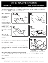
LISTADEREPUESTO$
6
\
7
/
Clave NO. PiezaNO. Descripci6n
1 97016971 Interruptorde Ventilador- Blanco(incluye interruptordela luz)
97016972 Interruptorde Ventilador- Almendra (incluyeinterruptorde laluz)
97016970 Interruptorde Ventilador- Negro(incluye interruptorde laluz)
97016973 Interruptorde Ventilador- Beige(incluye interruptorde laluz)
2 97016971 Interruptorde laLuz - Blanco(incluyeinterruptorde ventilador)
97016972 Interruptorde laLuz -Almendra (incluyeinterrupterdeventilador)
97016970 Interruptorde laLuz - Negro(incluyeinterruptorde ventilador)
97016973 Interruptorde laLuz - Beige(incluye interruptordeventilador)
3 R730088 Conjuntode Motor/Aspa
4 R610045 Filtro deAluminio(use conextractorducto solamente)
* R610050 Filtro -Bin Ducto
* R610051 Tacosde Filtro- SinDucto
5 R566088 Portafoco
6 99091020 Cubiertade Venteada- Blanco
99091021 Cubiertade Venteada-Almendra
99091022 Cubiertade Venteada- Negro
99091027 Cubiertade Venteada- Beige
7 R6689601 Cubierta parala ConexionElectrica- Blanco
R6689602 Cubierta parala ConexionElectrica-Alrnendra
R6689604 Cubierta parala ConexionElectrica- Negro
R6689605 Cubierta parala ConexionElectrica- Beige
* No ilustrado.Cornpreperseparado.
GARANTIA
GARANTIA LIMITADA DE BROAN-NUTONE DE UNA[_O
Broan-NuToneie garantizaal consumidorcomprador original desus productosque tales productos estar&niibres
de defectos en materialeso manode obra porun pedodo de un ahoa partirde la fecha de compra original. NO
HAYOTRAS GARANTIAS EXPLICITAS0 IMPLICITAS,INCLUYENDO,PERO NO LIMITADASA GARANTIAS
IMPLICITASDE COMERCIALIZACIONOAPTITUD PARAUN PROPOSlTOPARTICULAR.
Durante estepe¢lodode un aiio, Broan-NuTonereparara o cambiara,a su opci6n y sin cobra, cualquierpraducto
o piezaque seencuentredefectuosa bajo uso y servicio normal.
ESTAGARANTIANO SE EXTIENDE AARRANCADORES DELAMPARASFLUORESCENTES YTUBOS. Esta
garantianocubre (a)mantenimientoy servicionarmales o(b)cualquier praductoopieza quahayan sidosometidos
a uso equivacado, negligencia, accidente, mantenimiento o reparaci6n indebida (excepto por Broan-NuTone),
instalaci6ndefectuosa o instalaci6n contrariaalas instruccionesde instalaci6n.
La duraci6n de cualquiergarantia implicita se limita a un perioda de un ai3osegOnse especificaen la garantia
explicita.Algunos estados no permitenlimitaci6n a la duraci6nde unagaranfla implicita,por Ioqueesta limitaci6n
talvez nose aplica alcaso suyo.
LAOBLIGACION DE BROAN-NUTONEDE REPARAR0 CAMBIAR,A OPCION DE BROAN-NUTONE,SERA
EL UNICOY EXCLUSIVO REMEDIOAL COMPRADORBAJO ESTAGARANTIA. BROAN-NUTONENO SERA
RESPONSABLE POR DAi/OS INC[DENTALES, CONSECUENTES,0 ESPECIALESQUE SURJAN DE 0 EN
RELACIONAEL USO 0 DESEMPENODEL PRODUCTO.Algunosestadosno permitenla exlusi6no limitaci6n de
dahos incidentaleso consecuentes,por Ioqueesta limitaci6n o exclusi6ntalvez nose aplicaen sucaso.
Estagarantia le da derechos legales espe_ficos, y usted puede tener atros derechas que va¢lande estadoa
estado.Esta garanfla reemplazatodas lasgarantias anteriores.
Paracalificar paraservicia bajo estagaranfla, usteddebe(a) notificar a Broan-Nutoneen ladirecci6n queaparece
abaja a al telefono 1-800-637-1453, (b) dar el nOmerode modela y la identificaci6n de pieza y (c) describir el
defecto en el producto o pieza.AI solicitar servicio bajo la garantia, usted debe presentarevidenciade la fecha
de compraoriginal.
Broan-NuTc_leLLCHarlford,WL_consinw_'_,.braal.com800-558-1711
626850 99043005G
  • Page 1 1
  • Page 2 2
  • Page 3 3
  • Page 4 4
  • Page 5 5
  • Page 6 6
  • Page 7 7
  • Page 8 8

Broan 433004 Owner's manual

Category
Cooker hoods
Type
Owner's manual
This manual is also suitable for

Ask a question and I''ll find the answer in the document

Finding information in a document is now easier with AI

in other languages