Page is loading ...

1
HOMEOWNER’S INSTALLATION AND OPERATING INSTRUCTIONS
ELECTRIC FIREPLACE INSERT
MODEL #25-900-001
For installation with
Comfort Glow
Fireplace Mantel
Questions, problems, missing parts? Before returning to your retailer, call our
customer service department at 1-800-776-9425,
8:30 a.m. –5:00 p.m. EST, Monday – Friday.
20-10-213 Rev.4/14
C US
INSTALLER: Leave this manual with the appliance.
CONSUMER: Retain this manual for future reference.
WARNING!
IF THE INFORMATION IN THIS MANUAL IS NOT FOLLOWED EXACTLY,
AN ELECTRICAL SHOCK OR FIRE MAY RESULT
CAUSING PROPERTY DAMAGE, PERSONAL INJURY OR LOSS OF LIFE.
IMPORTANT INSTRUCTIONS
PLEASE READ THIS MANUAL BEFORE INSTALLING AND USING APPLIANCE
Français p. 19
Español p. 39

2
IMPORTANT: Read all instructions and warnings carefully before starting Installation.
Failure to follow these instructions may result in a possible electric shock, injury to
persons, re hazard and will void the warranty.
Please read the Installation & Operating Instructions before using this appliance.
TABLE OF CONTENTS
Safety Information .........................................................................................................................3-5
Installation Instructions ..................................................................................................................6-9
Operation Instructions ...............................................................................................................10-12
Care and Maintenance ...................................................................................................................13
Electric Wiring Diagram ..................................................................................................................14
Troubleshooting ..............................................................................................................................15
Warranty ......................................................................................................................................... 16
Replacement Parts List ..................................................................................................................17
Thank you and congratulations on your purchase of a
Comfort Glow electric replace.

3
Please read and understand this entire manual before attempting to assemble, operate or install
the product. If you have any questions regarding the product, please call customer service at
1-800-776-9425, 8:30 a.m. –5:00 p.m. EST. – Friday.
1. Read all instructions before using this appliance.
2. This appliance is hot when in use. To avoid burns, do not let bare skin touch hot surfaces.
If provided, use handles when moving this appliance. Keep combustible materials, such as
furniture, pillows, bedding, papers, clothes and curtains at least 3 ft. (914 mm) from the front
of this appliance.
3. CAUTION: Extreme caution is necessary when any heater is used by or near
children, invalids, or pets and whenever the heater is left operating unattended.
4. If possible always unplug this appliance when not in use.
5. Do not operate any heater with a damaged cord or plug or after the appliance malfunctions,
has been dropped or damaged in any manner.
6. Anyrepairstothisapplianceshouldbecarriedoutbyaqualiedserviceperson.
7. Undernocircumstancesshouldthisappliancebemodied.Partshavingtoberemovedfor
servicing must be replaced prior to operating this appliance again.
8. Do not use outdoors.
9. This heater is not intended for use in bathrooms, laundry areas and similar indoor locations.
Never place this appliance where it may fall into a bathtub or other water container.
10. Do not run cord under carpeting. Do not cover cord with throw rugs, runners or the like.
Arrangecordawayfromtrafcareasandwhereitwillnotbetrippedover.
11. To disconnect this appliance, turn controls to the off position, then remove plug from outlet.
12. Connect to properly grounded outlets only.
13. This appliance, when installed must be electrically grounded in accordance with local codes,
with the current CSA C22.1 Canadian Electrical codes or for USA installations, follow local
codes and the National Electric Code, ANSI/NFPA No. 70.
14. Do not insert or allow foreign objects to enter any ventilation or exhaust opening as this may
causeanelectricshock,reordamagetheappliance.
15. Topreventpossiblere,donotblockairintakesorexhaustinanymanner.Donotuseonsoft
surfaces, like a bed, where openings may become blocked.
16. This appliance has hot and arcing or sparking parts inside. Do not use it in areas where
gasoline,paintorammableliquidsareusedorstored.Thisapplianceshouldnotbeusedas
a drying rack for clothing, nor should Christmas stockings or decorations be hung on or near it.
17. Use this appliance only as described in this manual. Any other use not recommended by the
manufacturermaycausere,electricshockorinjurytopersons.
18. Avoid the use of an extension cord because of the risk of overheating the cord and the risk
ofre.Extensioncordsarefortemporaryuseonly.Ifanextensioncordmustbeused,it
mustbeUL/CSAcertied,ratedat15A(1875W),125Vmaximumwith14AWGminimum
and constructed of two current carrying conductors with ground. A heavy duty extension cord
with the shortest length possible for the connection is recommended and must not be longer
than 50 ft. (15.2 m). Do not coil or cover the extension cord.
SAFETY INFORMATION SAVE THESE INSTRUCTIONS

4
Figure 1
SAFETY INFORMATION
Electrical Connection
Grounding Instructions
A15-Amp,120-Volt,60Hzcircuitwithaproperlygroundedoutletisrequired.
Preferably,thereplacewillbeonadedicatedcircuitasotherappliancesonthe
same circuit may cause the circuit breaker to trip or the fuse to blow when the heater
is in operation. The unit comes standard with a 6 ft. (1.8 m) long three wire cord,
exitingtherightsideofthereplace.Plantheinstallationtoavoidtheuseofan
extension cord. Extension cords are for temporary use only. If an extension cord
mustbeused,itmustbeUL/CSAcertied,ratedat15A(1,875W),125Vmaximum
with 14 AWG minimum and constructed of two current carrying conductors with
ground. A heavy duty extension cord with the shortest length possible for the
connection is recommended and must not be longer than 50 ft. (15.2 m).
Do not coil or cover the extension cord.
Electrical outlet wiring must comply with local building codes and other
applicableregulationstoreducetheriskofre,electricalshockandinjury
to persons.
Donotusethisreplaceifanypartofithasbeenunderwater.Immediately
callaqualiedservicetechniciantoinspectthereplaceandreplaceanypart
of the electrical system which has been under water.
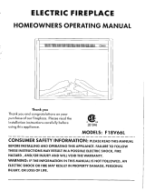
This heater is for use on 120 volts. The cord has a plug as shown at (A) in Figure 1.
An adapter as shown at (C) is available for connecting three-blade grounding-type
plugs to two-slot receptacles. The green grounding lug extending from the adapter
must be connected to a permanent ground such as a properly grounded outlet box.
The adapter should not be used if a three-slot grounded receptacle is available.
NOTE: Adapters are NOT
for use in Canada.
DANGER
GROUNDING
PIN
METAL SCREW
GROUNDING
MEANS
COVER OF GROUNDED
OUTLET BOX
ADAPTER
GROUNDING
PIN
(A)
(B)
(D)
(C)

5
SAFETY INFORMATION
Remote Control
ELECTRICAL, PLUMBING OR GAS LINES MAY BE IN WALL.
Before cutting, drilling or hammering verify their location. If needed, contact your
electrician, plumber or service person.
PRODUCT DAMAGE MAY OCCUR.
Never attempt to disassemble or alter the product in any way not instructed by this manual.
This equipment has been tested and found to comply with the limits for a Class B digital device,
pursuant to Part 15 of the FCC Rules and Industry Canada ICES-003. These limits are designed
to provide reasonable protection against harmful interference in a residential installation. This
equipment generates, uses, and can radiate radio frequency energy and, if not installed and used in
accordance with the instruction manual, might cause harmful interference to radio communications.
However,thereisnoguaranteethatinterferencewillnotoccurinaparticularinstallation.Ifthis
equipment does cause harmful interference to radio or television reception, which can be determined
by turning the equipment off and on, the user is encouraged to try to correct the interference by one
or more of the following measures:
• Reorient or relocate the receiving antenna.
• Increase the separation between the equipment and receiver.
• Connect the equipment into an outlet on a circuit different from that to which the receiver
is connected.
• Consultthedealeroranexperiencedradio/TVtechnicianforhelp.
The remote control requires 1 Lithium Coin Cell Battery (size CR2025), which is included.
DO NOT mix old and new batteries.
DO NOT use rechargeable silver oxide cell batteries with remote control unit.
DO NOT mix alkaline, standard (Carbon-Zinc), or rechargeable (Nickel-Cadmium) batteries.
DONOTdisposeofbatteriesinre.Improperdisposalmaycausebatteriestoleakorexplode.
WARNING
CAUTION

6
INSTALLATION INSTRUCTIONS
Fireplace Dimensions
Specications
120VAC
60Hz
1350W
12A
24-1/4 in. (616 mm)
9-13/32 in. (239 mm)
20-1/4 in. (514 mm)
Frequency
Voltage
Heater Rating
Max. Amps
Width
Depth
Height

7
INSTALLATION INSTRUCTIONS
Package Contents
PART DESCRIPTION QUANTITY
A Mounting Bracket Kit 2
B Screw (ST4) 4
C Infrared Remote Control 1
JY-3B
A
B
C

8
Clearance to Combustibles
Sides 2-27/64 in. (61.5 mm)
Floor 0 in. (0 mm)
Top 2 in. (51 mm)
Front 36 in. (914 mm)
Rear 25/32 in. (20 mm)
Wooden Facing 5/16 in. (8 mm)
[up to 5/8 in. (16 mm) thick]
• Out of direct sunlight
• Not susceptible to moisture
• Away from uninsulated outside wall
• At least 3 ft. (.9 m) from drapery, furniture and other combustibles
The Fireplace should be located in an area:
INSTALLATION INSTRUCTIONS
Open the unit and check carefully for visible damage. If you have any problems with installation,
operation, missing parts, or damage,please call 1-800-776-9425 for service.
DO NOT dispose of packaging until you are satised with your replace.
DO NOT return unit to store before calling 1-800-776-9425 for service.
PREPARATION
Before beginning assembly of product, make sure all parts are present. Compare parts with package
contents list and hardware contents. If any part is missing or damaged, do not attempt to
assemble the product. Contact customer service for replacement parts.
Estimated Assembly Time: 15 minutes
Phillips Screwdriver (not included)

9
INSTALLATION INSTRUCTIONS
1. Place the assembled mantel near a 15-amp, 120-volt grounded electric outlet.
Read all instructions before using this appliance.
2. Place the insert directly in front of the mantel opening.
3. Carefullylifttheinsertthroughthecenteropeninginthefrontofthereplace.Thebottomofthe
insert has two foam rubber strips to prevent scratching of the hearth base. Slide the insert back
through the opening until the metal trim makes contact with the front of the mantel.
4. Install the mounting brackets provided with the insert in the pre-drilled holes on the bottom of the
insert (see Figure 2).
5. Carefullypositionmantelwithinstalledreplaceagainstwall.
6. Plug the power cord into the 15-amp, 120-volt outlet. Use an extension cord rated for a minimum
of 1,875 watts if necessary.
CAUTION: Make sure that the unit is installed so that the
power cord is not compressed against or caught on the unit
or the mantel and that it has an unobstructed path to the
grounded outlet.
Infrared Remote Control
Figure 2
Mounting Brackets

10
OPERATING INSTRUCTION
Thereplacefeaturesconvenientlyseparatecontrolsforameeffectandforheatercontrol.
This allows you to operate the unit in two (2) different modes:
• As a full-featured replace-bothameeffectandheaterareon.Thismodeallowsyoutoenjoy
thelookoftherealongwiththeheatoutputofaheater.
• As a visual effect-onlytheameeffectison,theheaterisoff.Werecommendthismodefor
warmweatherapplication,whenyouwanttheambianceofare,withoutanyheatoutput.
Thereplacecontrolfunctionscanbeaccessedintwo(2)ways:
• Usingthetouchpadcontrolpanel,locatedintheupperright-handcornerofthereplace
behind the sliding control panel cover.
• Using the multifunction remote control unit.
1
3
4
2
Figure 4
1 6 5234
Main Power Button:
Thisbuttonsuppliespowertoallthefunctionsofthereplace.TheMainPowerbuttonmustbe
in the ON position, either from the remote or on the touch pad for the functions to work.
Heater Control Button:
This button controls the heater ON/OFF and 11 temperature modes from 68°F (20°C) to 88°F
(31°C).Whentheheaterisrstturnedon,itwillcomeonatthelowestroomtemperaturesetting
68°F(20°C).EachtimetheHeaterControlbuttonispressed,thetemperaturesetpointincreases
2°F(1°C),allowingyoutoadjusttheambienttemperature,upto88°F(31°C).Thereplacewill
remember the last heat setting, and in later use, the heater will start at that setting, unless power
to the unit has been interrupted.
Flame Control button:
ThisbuttoncontrolsthebrightnessoftheameeffectwithsettingsatHigh,MediumandLow.
Whenthereplaceisrstturnedon,theamewillcomeonatthehighestsetting.Thereplace
willrememberthelastamesettingusedandinlaterusetheamebrightnesswillstartatthat
setting, unless power to the unit has been interrupted. Each time the Flame button is pressed, the
amebrightnessdecreases.Theonlywaytoturnofftheameeffectcompletelyistoturnoffthe
Main Power button.
Timer Button:
This button controls the timer ON/OFF and 10-time setting from 30 minutes to 9 hours. When the
Timerisrstturnedon,itwillcomeonattheshortesttimesetting(30minutes).Eachtimethe
Timer button is pressed, the time increases 1 hour, up to the longest setting (9 hours). Once the
settimeexpires,allreplacefunctionswillbeautomaticallyturnedoff.

11
OPERATING INSTRUCTION
5
6
Fahrenheit/Celsius Display:
This button displays F (Fahrenheit) or C (Celsius) depending on how the temperature mode is set.
Whenthereplaceisrstturnedon,theFahrenheit(F)temperaturewillbedisplayed.Toswitch
fromFahrenheittoCelsius,orvise-versa,whenHEATERisON,holdHEATERCONTROLbutton
for10seconds.Thereplacewillrememberthelasttemperaturemodesetting,andinlateruse,
the display will start at that setting, unless power to the unit has been interrupted.
Temperature/Timer Display
This LED display shows the set point for the temperature and timer functions. When either of
thesefunctionsisactivated,thedisplayreectsthesetpointforvesecondsandthenfadesto
black. Any change in the set point of the temperature or timer will reactivate the display, which
againfadesafterveseconds.
Theinfraredremotecontrolreliesonalineofsightandmustbepointedattheame/screenofthe
replacetowork.TheremotecontrolunithasthecontrolsrequiredtoturnON/OFF both the main
powerandtheheater.Ifyouprefertousethetouchpadcontrolonthereplaceunititself,openthe
control panel sliding cover to access the touchpad buttons.The layout of the buttons on touchpads
and remote control unit can be seen in Figures 4 and 6, respectively.
1.Plugyourreplaceintoa15-amp,120-voltpoweroutlet.
2. Turn the power on. Flame will show on the back screen
ofthereplace.
3. Remove plastic tab from inside battery compartment
to activate remote control.
4.Pointtheremotecontroldirectlyatthereplace
ame/screenandusethebuttonstooperatethe
replace.
The plastic tab inside the battery
compartment MUST be removed
before remote control will operate.
Figure 5
(Pull tab)
Battery Replacement Procedure:
(Size CR2025)
Battery replacement instruction
CR2025
OPEN
PUSH
RELEASE
NOTE: Afterthereplacehasbeenoperating,whentheunitisturnedoff,thefan(nottheheater)
will continue to run for about 1 minute to cool down the interior of the unit. During this time, you
may feel cool air from the blower outlet. This is normal and does not require any action. The fan will
stop once the interior cools down.

12
Main Power Button:
This button supplies power to all the functions of the
replace.ThemainpowerbuttonmustbeintheON position,
either from the remote or on the touch pad for the functions
to work.
Timer Button:
This button controls the timer ON/OFF and 10-time setting
from30minutesto9hours.WhentheTimerisrstturned
on, it will come on at the shortest time setting (30 minutes).
Each time the Timer button is pressed, the time increases 1
hour, up to the longest setting (9 hours). Once the set time
expires,allreplacefunctionswillbeautomaticallyturnedoff.
Flame Control button:
Thisbuttoncontrolsthebrightnessoftheameeffectwith
settingsatHigh,MediumandLow.Whenthereplaceisrst
turnedon,theamewillcomeonatthehighestsetting.The
replacewillrememberthelastamesettingusedandin
laterusetheamebrightnesswillstartatthatsetting,unless
power to the unit has been interrupted. Each time the Flame
buttonispressed,theamebrightnessdecreases.Theonly
waytoturnofftheameeffectcompletelyistoturnoffthe
Main Power button.
Heater Control Button:
This button controls the heater ON/OFF and 11 temperature
modes from 68°F (20°C) to 88°F (31°C). When the heater is
rstturnedon,itwillcomeonatthelowestroomtemperature
setting68°F(20°C).EachtimetheHeaterControlbutton
is pressed, the temperature set point increases 2°F (1°C),
allowing you to adjust the ambient temperature, up to 88°F
(31°C).Thereplacewillrememberthelastheatsetting,and
in later use, the heater will start at that setting, unless power
to the unit has been interrupted.
NOTE: To switch between Fahrenheit/Celsius modes see
control panel Fahrenheit/Celsius display instructions.
OPERATING INSTRUCTION
1
2
3
4
Figure 6
2
3
4
1
IMPORTANT: Under normal operation, when power is interrupted from either an outage or from
unplugging unit from wall while still in operation, error code “EC” may appear on the LCD control panel
and the unit will cease operation. In order to reset, unplug the unit for 10 minutes, then plug back in for
normal operation in accordance with the Use and Care Guide.

13
CARE AND MAINTENANCE
Glass Information:
Maintenance of Motors:
Cleaning:
Before attempting ANY maintenance:
1. Turn off power to the unit.
2. Unplug the power cord from outlet.
3. Letreplacecoolifithasbeenoperating.
1. Under no circumstances should this product be operated with broken glass.
2. Do not strike or slam the glass.
3. Do not use abrasive cleaners to clean the glass.
4. This product uses tempered glass. Replacement of the glass supplied by the manufacturer
shouldbedonebyaqualiedserviceperson.
Always disconnect the appliance from the main power supply and allow it to cool before any
servicing operation.
Themotorsusedonthefanheaterandameblowerarepre-lubricatedforextendedbearinglifeand
requirenofurtherlubrication.However,periodiccleaning/vacuumingoftheappliancearoundtheair
intake and exhaust, as well as the fan heater is recommended. For heavy or continuous use, periodic
cleaning must be done more frequently. If the heater blows alternating cold and warm air, check the
fanforfreemovementandfordebrisrestrictingairow.Ifthefandoesnotmovefreely,theunitmust
be turned off and the fan replaced immediately in order to prevent further damage to the unit.
Cleaningofthecontrolpanel,locatedintheupperright-handcornerofthereplacebehindthe
sliding control panel cover, is to be done only using a soft cloth, slightly dampened in water
(if needed, a small amount of dish soap can be added to the water) and dried using a clean,
dry soft cloth. Cleaning of the screen diffuser is to be done using only water and a lint free cloth.
DO NOT use any abrasive household cleaners as these products will damage the touch-pad
controls and the diffusing screen.

14
Disconnect power before servicing.
Anyelectricalre-wiringofthisappliancemustbedonebyaqualiedelectrician.
This wiring must be done in accordance with local codes and/or in Canada with
the current CSA C22.1 Canadian Electrical Code, and for US installations, the
National Electrical Code ANSI/NFPA NO 70.
If repairing or replacing any electrical component or wiring, the original
wire routing, color coding and securing locations must be followed.
DANGER
Any electrical repairs or rewiring of this unit should be carried out by a licensed electrician in
accordance with national and local codes.
ELECTRIC WIRING DIAGRAM
CIRCUIT DIAGRAM
WARNING: Disconnect power before servicing.

15
TROUBLESHOOTING
If you have any questions regarding the product, please call customer service at 1-800-776-9425,
8:30 a.m. –5:00 p.m. EST, Monday – Friday.
Problem Possible Cause Corrective Action
Fireplace does
not operate; the
ON/OFF power
light on the control
panel is not lit.
Power light is ON
butthebackame
is not bright/visible.
Power light is ON
but the ember bed
ameisnot
ickering.
Excessive noise
whentheameis
ON but the heater
OFF.
Excessive noise
when the heater
is operating.
Heaterisnot
operating.
1.Thereplaceisnot
plugged in.
2. A circuit breaker is tripped
or a fuse blown.
3. Defective ON/OFF switch.
4. Loose wiring.
1. Incorrect operation.
2. LED strip not functioning.
3. Loose wiring.
1. LED strip not functioning.
2. Loose wiring.
1.Rotatingamereector
shaft rubbing against
housing.
2.Defectiveamereector
shaft motor.
1. Dirty or clogged blower.
2. Defective heater assembly.
1. Incorrect operation.
2. Defective heater switch.
3. Defective heater assembly.
4. Loose wiring.
5. Dirty or clogged sliding door.
6. Thermostat has been
satised
1.Makesurethereplaceispluggedin
toastandard120Voutlet.
2. Check additional appliances on the
circuit;ideallythereplaceshouldbe
on a dedicated 15-amp circuit.
3. Call customer service: 1-800-776-9425.
4. Call customer service: 1-800-776-9425.
1. Refer to operating instructions.
2. Call customer service: 1-800-776-9425.
3. Call customer service: 1-800-776-9425.
1. Call customer service: 1-800-776-9425.
2. Call customer service: 1-800-776-9425.
1.Openbackofreboxandreposition
amereectorshaft.Turnoffunitprior
to servicing.
2. Call customer service: 1-800-776-9425.
1. Refer to Maintenance of Motors in
Care and Maintenance.
2. Call customer service: 1-800-776-9425.
1. Refer to operating instructions.
2. Call customer service: 1-800-776-9425.
3. Call customer service: 1-800-776-9425.
4. Call customer service: 1-800-776-9425.
5. Unplug the unit. Clear door area of dust
anddebris.Waitveminutes,plugthe
unit in again and turn on the heater.
6. Increase desired room temperature on
the control panel/remote

16
Themanufacturerwarrantsthatyournewelectricreplaceisfreefrommanufacturingand
material defects for a period of one year from date of purchase, subject to the following conditions
and limitations.
1. Thiselectricreplacemustbeinstalledandoperatedatalltimesinaccordancewiththe
instructions furnished with the product. Any alteration, willful abuse, accident, or misuse of the
product shall nullify this warranty.
2. This warranty is non-transferrable, and is made to the original owner, provided that the purchase
wasmadethroughanauthorizedsupplierofthemanufacturer.
3. This warranty is limited to the repair or replacement of part(s) found to be defective in material
or workmanship, provided that such part(s) have been subjected to normal conditions of use and
service,aftersaiddefectisconrmedbythemanufacturer’sinspection.
4. The manufacturer may, at its discretion, fully discharge all obligations with respect to this warranty
by refunding the wholesale price of the defective part(s).
5. Any installation, labor, construction, transportation, or other related costs/expenses arising from
defective part(s), repair, replacement, or otherwise of same, will not be covered by this warranty,
nor shall the manufacturer assume responsibility for same. Further, the manufacturer will not be
responsible for any incidental, indirect, or consequential damages, except as provided by law.
6. All other warranties - expressed or implied - with respect to the product, its components and
accessories, or any obligations/liabilities on the part of the manufacturer are hereby expressly
excluded.
7. Themanufacturerneitherassumes,norauthorizesanythirdpartytoassume,onitsbehalf,
any other liabilities with respect to the sale of this product.
8. The warranties as outlined within this document do not apply to non-manufacturer accessories
used in conjunction with the installation of this product.
This warranty is void if:
a) Thereplacehasbeenoperatedinatmospherescontaminatedbychlorine,uorineorother
damaging chemicals.
b)Thereplaceissubjectedtoprolongedperiodsofdampnessorcondensation.
c) Any alteration, willful abuse, accident, or misuse of the product.
IF WARRANTY SERVICE IS NEEDED . . .
1) Contact customer service. Make sure you have your warranty, your sales receipt, and the
model/serial number of your product.
2)DONOTATTEMPTTODOANYSERVICEWORKYOURSELF.
WARRANTY
World Marketing of America, Inc.
P.O. Box 192, Mill Creek, PA, 17060-0192

17
REPLACEMENT PARTS LIST
For replacement parts, please call customer service at 1-800-776-9425, 8:30 a.m. –5:00 p.m. EST,
Monday – Friday.
Ref.
1
2
3
4
5
6
7
8
9
10
11
12
13
14
15
16
17
18
19
EF33405A-12
EF23350AC
EF23106AC
EF23107AC
EF23354AC
EF23108AC
EF23356AC
Description
Top panel
Trim assembly
Flame panel
Mounting bracket kit
Heater
Right side panel assembly
Back panel
Screen
Left side panel assembly
Remote control
Control panel graphic
Power cord & connector
Control panel circuit board
Flame reflector
Ember bed-LED strip
Flame-LED
Logset
EF23373AS-12
EF28368AC
EF23511A-12
EF23374A-14Air channel
B-Motor
25-900-001
EF28369AS
EF23371AS
EF18512AC-12
EF33510AS-12
EF33515A
EF33508A
EF33501A-IR
EF23372AC

18
Printed in China

1
SARDONIA COMPACT
FIREPLACE
MODEL #EF5538
Questions, problems, missing parts? Before returning to your retailer, call our
customer service department at 1-800-776-9425, 8:30 a.m. –5:00 p.m. EST,
Monday – Friday.
C US
INSTALLER: Leave this manual with the appliance.
CONSUMER: Retain this manual for future reference.
WARNING!
IF THE INFORMATION IN THIS MANUAL IS NOT FOLLOWED EXACTLY,
AN ELECTRICAL SHOCK OR FIRE MAY RESULT
CAUSING PROPERTY DAMAGE, PERSONAL INJURY OR LOSS OF LIFE.
IMPORTANT INSTRUCTIONS
PLEASE READ THIS MANUAL BEFORE INSTALLING AND USING APPLIANCE
Español p. 12
ATTACH YOUR RECEIPT HERE
Serial Number ________________________________ Purchase Date _________________________________
20-10-206 Rev. 4/14
Francais p. 23

2
IMPORTANT: Read all instructions and warnings carefully before starting installation.
Failure to follow these instructions may result in a possible electric shock, injury to
persons, re hazard and will void the warranty.
Please read the Installation & Operating Instructions before using this appliance.
TABLE OF CONTENTS
Safety Information .........................................................................................................................3-4
Package Contents .........................................................................................................................5-6
Operating Instructions ......................................................................................................................7
Care and Maintenance .....................................................................................................................8
Electric Wiring Diagram ....................................................................................................................9
Troubleshooting ..............................................................................................................................10
Warranty ......................................................................................................................................... 11
PRODUCT DAMAGE MAY OCCUR.
Never attempt to disassemble or alter the product in any way not instructed by this manual.
CAUTION
/