Page is loading ...

SM-LP-F-M / SM-LP-F-L
Strong™ Universal Low Prole Fixed Mount

WARNINGS:
• Installation by a qualied professional is highly recommended for this product.
• Do not begin installation until you have thoroughly read and understand these instructions.
• Ensure the mounting wall will safely support four times the combined weight of the Mount
and display panel.
• Under no circumstances should this product be mounted to metal studs.
• The manufacturer does not accept responsibility for incorrect installation.
TOOLS REQUIRED:
• Power Drill
• 5/16” and 1/4” Drill Bit
• Phillips Head Screw Driver
• Level
• Socket Wrench
with 1/2” Socket head
HARDWARE KIT
CAUTION:
These wall mounts are intended for use only with the maximum weight of: 88 lbs/39.9kg - SM-LP-F-M 165 lb/74.8 kg - SM-LP-F-L
Bag 2
Bag 3
Bag 1
Bag 4
Bag 5
Bag 6
Bag 7
(W) Concrete Anchor (x3)
(U) M8x63
Lag Bolt (x3)
(V) Lag Bolt
Washer (x3)
(S) M5 Washer (x16) (T) M8 Washer (x8)
(A) M4x10 Bolt (x4) (B) M4x20 Bolt (x4) (C) M4x30 Bolt (x4)
(D) M4x40 Bolt (x4) Large Model Only
(E) M5x10 Bolt (x4)
(G) M5x30 Bolt (x4)
(H) M5x40 Bolt (x4) Large Model Only(F) M5x20 Bolt (x4)
(I) M6x10 Bolt (x4) (J) M6x20 Bolt (x4) (K) M6x30 Bolt (x4) (L) M6x40 Bolt (x4) Large Model Only
(M) M8x10 Bolt (x4) (N) M8x20 Bolt (x4) (O) M8x30 Bolt (x4) (P) M8x40 Bolt (x4)
(Q) M4/M5
Nylon Spacer (x8)
(R) M6/M8
Nylon Spacer (x8)

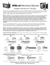
INSTALLATION:
Step 1: Mounting the Wall Bracket Assembly
For Mounting on a Stud Wall
a. Pre-drill holes into two wood studs using a 1/4” drill bit.
Be sure to drill into the center of the studs at least
2-1/2” deep. The use of a stud nder is highly
recommended.
b. Insert two Lag Bolts (W) into holes through the Wall
Plate and tighten down (Figure 1).
WARNING: Tighten bolts so that wall plate is rmly
attached, but do not overtighten. Overtightening
can damage the bolts, greatly reducing their
holding strength.
For Mounting on a Concrete Wall
a. Pre-drill three holes into concrete using 5/16” drill bits
to a depth of 2-1/2”. Insert concrete wall anchors (U)
and tap in with hammer, if necessary (Figures 2 & 3).
WARNING: When installing wall arm assembly on
cinder block, verify rst that you have a minimum
of 1-3/8” of concrete thickness to be used for the
concrete anchors. Do not drill into mortar joints! Be
sure to mount in a solid part of the block, generally
1”minimum from the side of the block. Cinder block
must meet ASTM C-90 specications. It is suggested that
a standard electric drill on slow setting is used to drill the
hole instead of a hammer drill to avoid breaking out the
back of the hole when entering a void or cavity.
Concrete must be 2000 psi density minimum.
Lighter density concrete may not hold concrete
anchor.
Make sure that the supporting surface will safely
support the combined load of the equipment and
all attached hardware and components.
b. Insert three Lag Bolts (U) into the wall anchors
through the Wall Plate. Tighten all bolts (Figure 4).
WARNING: Tighten bolts so that wall plate is rmly
attached, but do not overtighten. Overtightening
can damage the bolts, greatly reducing their
holding strength.
Step 2: Mount Arms to television
a. Determine the diameter of the screw (parts A through
P) your TV requires by carefully trying to hand-thread
one into the threaded insert on the rear of the TV. If
there is any resistance, stop immediately.
b. Spacers are commonly needed on televisions with
curved backs or recessed screw inserts. The screw
will thread through the appropriate washer(S, T), any
spacer needed (Q, R) and the arms into the TV
(Figure 5).
c. Ensure the arms are installed at side to television
and are square to each other after all screws have
been installed (Figure 5).
d. Make sure all screws are secure, but do not over-tight-
en them.
Correct
concrete
concrete
plaster/
drywall
plaster/
drywall
Incorrect
Cutaway View
Figure 2
Drill holes and
insert anchors.
Place wall arm
assembly plate
over anchor and
secure with
lag bolt.
Tighten all
lag bolts.
Wall Arm
Concrete
Wall
Lag Bolt
Figure 3
Figure 1
Figure 4
Figure 5

Step 3: Hang television on to the Wall Plate
a. Carefully lift the television to hook the arms over the top lip of the wall
plate. Allow the lower portion of the arms to swivel in under the bottom
lip of the wall plate. Do not release the television until it is completely
connected to the wall plate.
b. Insert the safety bar at the bottom of the mount to avoid having the
display knocked off the mount. A padlock can be used at one end to
help prevent theft.
Lifetime Limited Warranty
Strong™ Mounts have a Lifetime Limited Warranty. This warranty includes parts and labor repairs on all components found to be defective in material or workmanship
under normal conditions of use. This warranty shall not apply to products which have been abused, modied or disassembled. Products to be repaired under this
warranty must be returned to SnapAV or a designated service center with prior notication and an assigned return authorization number (RA).
For Technical Support call 1.866.838.5052
Lifetime
130122-0900
/