Page is loading ...

Use _ Care Guide
Ice k,'la k e_
Guia de Uso y Cuidado
M_q_Ji_la de hielo
Guide d'utilisation et d'entretien
Mach'i_le _ gla_o_ls

Electrolux Model Number
Electrolux Serial Number
Dealer Address
Dealer Name
Once you have your unit installed, we suggest
you keep this manual in a safe place for future
reference. Should any problems occur, refer to
the Troubleshooting section of this manual. This
information will help you quickly identify a problem
and get it remedied. In the event you require
assistance, please contact the dealer where you
purchased your unit.
Dealer Telephone
Keep this manual and the sales receipt together in
a safe place for further reference.
©2007 Electrolux HomeProducts, Inc.
Post Office Box 212378, Augusta, Georgia30917, USA
All rights reserved. Printed in the USA
For toll-free telephone support in the U.S. and
Canada: 1-877-4ELECTROLUX (1-877-435-3287)
For online support and product information visit
http://www.elect roluxusa.com

Finding Information
TaMe of Contents
FindingInformation ................................................. 2
Pleasereadandsavethis guide.............................................. 2
Keepa recordfor quick reference...........................................2
Questions?.............................................................................. 2
Tableof contents..................................................................... 3
Safety.................................................................. 4
Important SafetyInstructions .................................................4
Safety Precautions............................................................... 4
Definitions........................................................................... 4
GeneralPrecautions ............................................................ 4
Installation ............................................................ 5
Installation Dimensions .........................................................5
Installingthe Drain..................................................................5
GravityDrain................................................................... 5
Connectinga DrainPump....................................................... 6
Site Preparation...................................................... 7
Preparingthe Site ..................................................................7
Water Supply Connection........................................... 8
Connectingthe Water Supply..................................................8
Leveling............................................................... g
Leveling the Unit ..................................................................... 9
Operation............................................................ 14
NormalOperation.................................................................14
IceCubeThickness...............................................................14
IceDispenserOperationandCare.........................................14
IceCubeThicknessAdjustment............................................15
DrainPump...........................................................................15
Maintenance ........................................................ 16
Special Considerations .........................................................16
Maintaining andCleaningYour Ice Maker.............................16
ExteriorCleaning- As Required.........................................16
StainlessSteel Models.......................................................16
Interior Cleaning- As Required.........................................16
CondenserCleaning- Every3 Months ..................................17
Self Cleaning- Every6 Months.............................................17
Inlet Screen Cleaning- EveryYear........................................19
Storing, Vacationand Moving ................................... 19
Drainingfor Non-Use............................................................ 19
Troubleshooting.................................................... 20
BeforeyouCallforService....................................................20
If ServiceisRequired............................................................21
Warranty Information ............................................. 22

GeneraJ Precautions

Installation
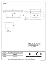
_nstallation Dimensions
34 - 1/8"
(86.7)
FULL
RETRACT
HEIGHT
WATER"
OUTLET
WATER
- DRAIN
24 _
I_ (61) _"
WATER
VALVE _ (_
(55.2)
_nstamlin9 the Drain
Drain lines must have a 1 inch drop per 48
inches of run (1/4 inch per foot) and must not
create traps.
The floor drain must be large enough to
accommodate drainage from all drains.
Insulate the bin drain line to prevent
condensation.
Model EI151M55GS can be installed using a gravity
drain or the Electrolux EIMP60, optional drain
pump kit.
Follow these guidelines when installing drain lines
to prevent water from flowing back into the ice
maker storage bin and/or potentially flowing onto
the floor causing water damage:
Gravity Drain
• Drain lines must have a 5/8 inch inside
diameter.
SCREWS
Figure 1

_!_!ii_i_i_;_!_!ii!_!_!_i_:i!i!!i!i!i_i_!i_i_!!i_i!!!i_i!!!i_i!!!i_i!!!i!i_!_!_i_!_!_i_!ii:i_i_i_i_i_i:_i_i_i_ii_i!!i_i_iii
Installation
connectingaorainpump
] Ifagravitydrainconnection isnotavailable, we
strongly recommend the useofthe Electrolux
EIMPeOdrain pump. The Electrolux EIMP60
drain pumpisavailablethrough your Dealer, or
directfrom Electroluxwith complete installation
instructions. Ifa pumpotherthan the Electrolux
EIMP6Odrain pump isto be used, itmustmeetthe
followingspecifications:
, it must be UL listed and have a UL listed
120VAC,3-w_regroundedpowercord.
• it must have overall maximum outside
d_me_s_onsofs-3J4'w_dexS-3J4'deepx
, 7-3/4' high.
It must have a minimum flow rate of 15
• gallonsperhouratlOfeetoflift.
Itmusthaveasealedsumpwhichdoesnot
allowwaterleakage in thecaseofa power
outage, restricted drain orpumpfailure.
.....::: , Itmusthaveacheckvalveinthedischarge
..... lineto preventwastewaterreturn tothe
pump.
, It must have an overflow protection control
which will shut off power to the ice maker in
the event of a pump failure.
• It must have an operating temperature range
of 50°F to 110°F (10°C to 43°C).

iiiiii_i!@ii!!iiii!iiiii!ili_iiii!_@i,i!ii,!!!i@i!i_iii_ii!_ili
Site Preparation
Pr fir% th it 7 iThelundmuSstnbeornd_tnanedeaCC°rdngt°Y°Ur
÷pa _ e S ÷
1 Position the unit on a flat, level surface,
capable of supporting the entire weight of
the unit. Remember that the unit will be
significantly heavier once it is fully loaded.
2 The surrounding air temperature must be at
least 50°F (10°C) but must not exceed 1IO°F
(43°C).
3 The unit must not be located near heat-
generating equipment or in direct sunlight.
Figure 2
OR WALL
0 II
CLEARANCE
NEEDED

_i:i_ii_iiJi_!ii:i_ii:i_ii:i_ii:i_ii:i_i_i:!ii_!:_ii_!:_ii_!:_ii_!:_i_!_ii_i_i!i_!;!;!_i_;ii_;!_i_ii_i_ii_%:i_!
Water Supply Connection
Connecting the Water Supply
When connecting the water supply follow these
gu de nes'
• , k W'at_: _nd _ltalD :::::: :
* Review the local plumbing codes before you
nsta the unt
......... i
* tne water pressure snoula De between 30
::: : and 120 psi.
4 Plug in the power cord•
[:_ _ N 5 Gentypushtheunt ntoposton fdesred
the un t may be recessed nto cab net or wa
6 Allow at least 1-1/2 inches clearance behind
the unit for electrical, water supply and drain
* Make certain a SmUT-OFF VALVE is installed connection s.
in the 1/4 inch water supply line.
* Connect sufficient tubing to the unit to
allow the unit to be moved for cleaning and
servicing• However, make certain that the
tubing is not pinched or damaged during
installation.
. Electrolux recommends the use of copper
..... tubing for installation• DO NOT use plastic
water supply line since it may crack or
rupture with age and may cause water
damage to your house•
Figure 6
WATER
Figure 5
1 Locate the compression fitting and ferrule
packed in the unit. Slide the compression
fitting and ferrule over the 1/4 inch water
supply line. Do not use thread sealing
compound or tape. Using two wrenches,
tighten the compression fitting on the supply
line (see Figure 6).
2 Carefully bend the water supply line into
position and connect the line to the solenoid
valve• Avoid kinking the water supply line.
3 For recessed installations, allow extra water
supply line length to provide slack for easy
removal from the recessed area (see Figure
8). This will also safeguard against kinking
the line.
WATER LiNE
Figure 7
Figure 8

Leveling
Leveling the unit
1 Use a level to check the levelness of the ice
maker from front to back and from side to
side (see Figure 10).
Figure 10
If the ice maker is not level, adjust the feet
on the corners of the unit as necessary (see
Figure 11).
Figure 11
Check the levelness after each adjustment
and repeat the previous steps until the unit is
level.

iiii!iiii;i:iii_i!i_i_i;!ii_i¸ilil¸iiiiiill¸_i_!;_!;_i_!_ii_;_!!ii_i_i_;i_!ii!_!_i_i!i_ii_!;i!!iiii!i:iii!i:iii!i_i_!_!;!!_!_!i_!
1(:} Door Reversal
Reversin 9 the Door (some models)
All Electrolux units may be left or right hand 2 Remove plastic screw plugs (3 top and 3
opening. The door opening is easily reversed by bottom) from new hinge location (see Figure
moving the hinge hardware to the opposite side 14), and remove hinge pin hole plug in top of
(see Figure 12). door(see Figure 15). Do not discard.
- __
SCREW
t _P'UGS
/ Figure
!
Figure 12
To reverse the door:
1 Remove top hinge screw pin from cabinet
using a Phillips ®head screwdriver (see
Figure 13). Remove door by tilting forward
and lifting off bottom hinge pin.
Figure 15
Figure 13
P _illps
3 Remove top hinge (3 screws), reinstall hinge
screw pin, and remount on opposite side
BOTTOM (see Figure 16).
HINGE ._
SCREW II
PIN _=_
Figure 16 UL313

Door Reversal
Remove the two door closer inserts from the
existing bottom hinge and install as shown on
the new bottom hinge (see Figure 17).
Figure 17
DOOR _.
CLOSER "_
iNSERTS
BOSS
5 Remove existing bottom hinge (3 screws)
and remount on opposite side TOR Remove
hinge screw pin.
6 With bottom of door facing up, remove pivot
plate (2 screws), flip over, and remount on
opposite side of door (see Figure 18).
Holding door upright with top of door tilted
forward, place hole of door pivot plate on
bottom hinge screw pin (see Figure 19). Be
sure that the bosses on the closers align with
holes in hinge and hinge plate.
Figure 19
8 Tilt top of door into position in top hinge and
install top hinge screw pin.
9 In empty hinge holes, install plastic screw
plugs (3 top and 3 bottom) and door hole
plug (1,door top) removed in step 2.
J
Figure 18

@i!_ii_!i_!!_!i_i!(_!ii_i!;ii_i!i;!_;!_;!@i:_i_i_i_i!_ii_@;!!_!_i;;_:iiii
Door Adjustment
A " tin th D r 4 fdooredgeoppostethe hnges needsto
dJus e CO
g move up, move plate toward outside of door.
Yourdoorisalignedatthefactorybeforeshipment. Ifdooredgeneedsto,movedown:move^,
Occasional re-adjustmentmaybenecessary, _a_etowara!ns,aeoTaoor_see P,gu[,e,zz!..
especially if an overlay panel is installed. The Hepea[ un[ll lop e.ageoTuoorls parallel wl[n
following procedurewillcorrectforupto 1/4" [opofcaDme[ana[,gn[enscrewssecure,y.
alignment•
Thedoorshould neverbefiush with thetopofthe Figure22
cabinet. Evenwhenlevel, thetopedgeofthedoor
will be 1/8 belowthetopofthecabinet(see Figure SLOTTED _ I _.._.r.. I
20). MOUNTING -_--_-__L_ J_ ...... I
HOLES I _ L]" I
Toadjust: I.--.dll_-,] I
1 Comparethetopedgeofthedoor(opposite Lt'qP-"_ I
the hinges) to the top edge of the cabinet RAISE _ LOWER I
and note the type of adjustment (up or down) OUTSIDE OUTSIDE I
needed DOOR EDGE DOOR EDGE
• I
2 Remove the top hinge pivot pin with a 5 After adjustment is complete remove the
Phillips <ehead screwdriver (see Figure 21) rlnnr PJn£Ar£frr_mthA hr_ttnm hinrlA P.IAan
an_tloiftld°°d°ffrbc_tt°mhlng:PlguBe;3_ieful thoroughly'andVa;piypetroie'um'j_H'ytot_e
mating surfaces of the closers (see Figure
..... 3 With door upside-down, loosen but do not 23). Be sure that bosses on closers align with
i_i!_!_i!i_ii_!i!_!_i!i_ii_!i!_!_i!i_ii_!i!_!_i!i_ii_!i!_!_i!i_ii_!i!_!_i!i_ii_!i!_!_i!i_ii_!i!_!_i!i_ii_!i!_!_i@!_!_i!i_i
remove the two hinge plate screws•
1I8"
7-1"
Figure 20
holes in hinge and hinge plate• Mount door
and install top hinge pivot pin.
Figure 23
i
DOOR_
CLOSER "_
INSERTS
BOSS

Built-in Installation / Start-Up
nstalling a Built° n
Your Electrolux product has been designed for
either free-standing or built-in installation. When
built-in, your ice maker does not require additional
air space for top, sides or rear. However, the front
grille must NOT be obstructed.
LIGHT,
UP DOWN BLACKOUT MODE
POWER ARROW DISPLAY ARROW & OTHER FUNCTIONS
Figure 24
!i i i ii i! ! ! !!!ii!iiiiiiiiiiiiiiiiiiiiiiiiiiiiiiiiiiiiiiiiiiiiii iiiiiiiiiiiiiiiiiiiiiiiiiiiiiiiiiiiiiiiiiiiiiiiiiiiiii iii ii 1¸ili!ii iiii !, :ii ! :i!iiioi ii !i i iiii ! ii iiiiiiiii ii iiii ii ii iiiiii iiii ii ii iiiiiiiiiii ii ii iiiiiiiiiii ii ii iiiiiiiiiii ii ii iiiiiiiiiii ii ii iiiiiiiiiii ii ii iiiiiiiiiii ii ii iiiiii i i
UnitDirnensinns
Mode
B151N55GS 14-15/16" 34-1/8" 24"
Blackout Mode (not Star=K certified)
t. Touch and hold the LIGHT button for ten
seconds, then release (the °F symbol will
flash briefly at the end of the ten second
period).
2. The control display will go dark for 36 hours.
3. To exit the Blackout Mode, repeat step t.
Normal Operating Sounds
All models incorporate rigid foam insulated
cabinets to provide high thermal efficiency and
components,maximum souInndreducspite oftithison foritechnology,t's interna lyourworkingmodel
may make sounds that are unfamiliar.
nitia Start-Up
Once installation and leveling is complete, the unit
is ready for initial start-up and operation. All units
are shipped with controls that are preset. No initial
adjustments are required.
Plug into a 115 volt polarized and grounded
electrical outlet.
Open the water supply valve at the main water
source.
To turn the unit on or off, touch and hold
the POWER button on the display panel for
approximately five seconds, then release.
• A small LED above the icon will illuminate to
confirm the touch of any controller icon.
The electronic display will show "ICE" when
the unit is on, and "OFF" when the unit is off.
Turning the unit off will override any other
control function.
Normal operating sounds may be more noticeable
because of the unit's environment. Hard surfaces
such as cabinets, wood/vinyl/tiled floors and
paneled walls have a tendency to reflect normal
operating noises.
Common refrigeration components and a brief
description of the normal operating sounds they
make are listed below. NOTE: Your unit may not
contain all the components listed.
• Compressor: The compressor makes a hum
or pulsing sound that may be heard when it
operates
Evaporator: Refrigerant flowing through an
evaporator may sound like boiling liquid.
Condenser Fan: Air moving through a
condenser may be heard.
Automatic Ice Maker: You will hear ice as it
drops from the mold into the ice bin/tray.
Water Valve: The water valve will make an
occasional buzzing sound and running water
will be heard.

iiii!iiii!ii!i!i!i!@i@!_!;ii{ilili!i@i_@ii
Operation
N rm I r ti n • Cube"sabbrig"" Eectrouxcear ce
0 a Ope a 0
makers produce a slab of ice that falls from
Theicemakerisdesignedtomakeclearice thevertical mold, relyingongravitytobreak
from most water sources on a consistent basis, the ice bridges. Depending on the control
Water is constantly circulated over the evaporator setting, and the fullness of the ice bucket, it
assembly. As the water freezes, gravity causes maybe necessary to tap the ice slab with the
any sediment to drop into the water trough and not ice scoop to break it apart.
becomeimbeddedintheice.Thisgives a clearer _ Di n r - r ti n - - r
icecubewitha lowmineralcontent.Whenthe ce s_ se u_ a o & _a e
ice reachesthedesired thickness, itfallsoffthe
evaporatorand intothestorage bin. Thecycle is The icecubethicknesscontrol isfactorysetfor
then repeated. Whe.ntheleveloficereachesthe bestoverallpefformance. Thefactorysettingis
top of the storage bm the unit shuts off As the ice
.... ' . designed to,maintainan icebridgeofapproximately
level in the bm drops the unit will automatically
, 1/16 to 1/8 under normal conditions resulting in a
restart to keep the b n fu Your un ts ce product on dimqe of a--roximatel 1/4" to 1/2" in de_th 'see
rate mayvaryaepenamg on manyconslaeratlons. Figure 26aand 26b). A fullercube with less of a
Ambient artemperatures, watertemperatures, dimple results in a thicker ice bridge. As the ice
condenser c can hess and ce-maker c can hess br d-e becomes th cker, the tendenc for the cubes
areallcontr, but,ngfactorstohowqu,cklythe.un,t tostUaytogetherasaslabincreases._bridge
produces ice Certain sounds are normal dunng
. .. ' .... thicker than 1/8 may cause cubes to over-fill the
[ne unl[s opera[ion. You may near [ne compressor ce bucket
or fan motor the water valve the water circulation
pumporicedroppingintotheicestoragebin. 114"TOl/2" 1116"TOl/8"
ice CubeThickness DIMPLE ICEBRIDGE
Your Electrolux ice maker uses advanced
technology to make ice that is crystal clear. This
technology cascades a flow of water over a chilled
ice mold that is mounted vertically so no water sits
in it. Because of this ice making technology, clear
ice cubes differ significantly from regular ice cubes.
Differences are illustrated in Figure 25.
'....J T
GOOD
Figure 26a
> DIMPLES
Figure 25
\ ICE BRIDGE
Dimples: Electrolux clear ice cubes have
"dimples" on one side from the cascading
water process.
Cube Variations: Cubes made from different
batches, or even cubes within the same
batch may have varying dimples, thickness
and/or sizes due to the cascading water
process.
BRIDGE BRIDGE
TOO THIN TOO THICK
DIMPLE \ LITTLE OR /
TOO DEEP \ NO DIMPLE
BAD
Figure 26b

Cu Thickness Adju ment
interval - As Required
Ice thickness adjustments are made using the
control panel as follows:
LIGHT,
UP DOWN BLACKOUT MODE
POWER ARROW DISPLAY ARROW & OTHER FUNCTIONS
Figure 27
1.
2.
To enter the thickness adjustment mode:
a. Touch and hold the UP ARROW button.
b. Touch and release the DOWN ARROW
button three times, then release the UP
ARROW button.
c. The display will switch to "0," to confirm
the thickness adjustment mode has
been selected.
The factory setting is "0," and the total
range of adjustment is -5 to +5. Use the
UP ARROW button to raise the setting
and thicken the ice bridge, or the DOWN
ARROW button to lower the setting to thin
the ice bridge.
3.
4.
5.
Touch and release the LIGHT button key to
exit the ice thickness adjustment mode.
Remove all ice from the storage bin.
Ice cubes inany given batch will vary, so
it is necessary to choose cubes from the
sample area (Figure 28) for comparison
when making adjustments. If further
adjustments are desired, repeat steps 1
through 4.
Operation
SAMPLE AREA
Figure 28

_i_i!i:i_!_i!i!_i!_ii!ii_i_iii_i:_i_!i:_i_!i:_i_!i_i_i_i!!i_i!!i_i!_!_;_i_i!ii_i_ii_:ii_:ii_i:!_i_i_!i_!i_i!_i_ii!ii;_:_ii;_:_ii!_i_i_!_!
Maintenance
i I n i r ti n • fanysurface dscoors or rustng appears
Speca Co sdea o s
........... clean it quickly with Bon-Ami or Barkeepers
• Per Des[ penormance Keep [ne un [ ou[ of .
• . Fnend Cleanser and a non-abraswe cloth.
: d,rect sunhght. Always clean in the direction of the grain.
• Turn the unit OFF and dispose of any ice Aways f n sh th s process wth a h gh qua ty
cubes iftheunitwill notbe used for5days all-in-onestainlesssteel cleaner/polish to
ormore. Prop dooropen to allowforair preventfurther probems
c rcu aton and prevent me d and m dew •
• USE OF ABRASIVE PADS SUCH AS
• Iftheambienttoemperature is expected to SCOTCHBRITEWILL CAUSETHE
drop below45 F (7 C) drain all waterfrom GRA N NG N THE STA NLESSTO
the unitto preventfreezing damage not BECOME BLURRED.
covered by the warranty • • •
• o o Rust that is allowed to hnger can penetrate
• High ambient temperatures; 110 F (43 C) or nto the surface of the sta ness stee and
higher may reduce the units ability to reach become impossible to remove.
Iowtemperaturesand mayalso reducethe
ice production rate.
Maintaining and Cleanin 9
Your cemaker
Periodiccleaningand propermaintenancewill
ensureefficiency, topperformance, andlong
life• The maintenance intervals listed are based
i_i!_!_i!i_ii_!i!_!_i!i_ii_!i!_!_i!i_ii_!i!_!_i!i_ii_!i!_!_i!i_ii_!i!_!_i!i_ii_!i!_!_i!i_ii_!i!_!_i!i_ii_!i!_!_i!i_ii_!i!_!_i!i_ii_!i!_!_i!i_i
on normal conditions. You may want to shorten
the intervals if you have pets or other special
considerations.
Exterior Cleaning - As Required
The door, grille and cabinet may be cleaned with a
mild detergent and warm water solution. Do not use
solvent based or abrasive cleaners.
Use a soft sponge and rinse with clean water. Wipe
with a soft, clean towel to prevent water spotting.
Stainless Steel Models
• Stainless steel models may discolor when
exposed to chlorine gas, pool chemicals, salt
water or cleaners with bleach.
Interior Cleaning - As Required
1 Disconnect power to the ice maker.
2 Open the door and remove any ice from the
storage bin.
3 Wipe down the interior and storage bin with
a solution of non-abrasive mild soap or
detergent and warm water. Rinse with clean
water.
4 Sanitize the bin with a solution of 1
tablespoon of bleach in 1 gallon of warm
water. Rinse thoroughly with clean water.
5 Check that all drain connections are in place.
• Keep your stainless unit looking new by
cleaning with a high quality, all-in-one
stainless steel cleaner/polish on a monthly
basis. Frequent cleaning will remove surface
contamination that could lead to rust. Some
installations will require cleaning on a weekly
basis.
• DO NOT CLEAN WITH STEEL WOOL PADS.
DO NOT USE CLEANERS THAT ARE
NOT SPECIFICALLY INTENDED FOR
STAINLESS STEEL (this includes glass, tile
and counter cleansers).
6 Reconnect to the unit.

Maintenance
Condenser Cleaning m Every
3 Months
To maintain operational efficiency, clean the
condenser every three months (depending on
environmental conditions, more or less frequent
cleaning may be necessary).
%# Cleaning -- Every 6 Months
To maintain operational efficiency, clean the unit
every six months (depending on water conditions
more or less frequent cleaning may be necessary).
If the ice maker requires more frequent cleaning,
consult a qualified plumber to test the water quality
and recommend appropriate treatment.
To remove and replace the grille for access to the
condenser fins follow this procedure (see Figure
29):
1 Remove the screws at each end of the grille.
2 Remove the grille.
Figure 29

_i_i!i:i_!_i!i!_i!_i!_!ii_ii!ii!!_!ii_i_!_i_i;!_!_;!i!_i_i!_i!_i_:;i_!i_i!i!!_i_iii_;_!i_ii_i_i_i_!_i_!_;i_!i!i!_!_i_i_!ii_!_!_!i
Maintenance
2 Removeallicefromthestoragebin. 8 Reinstallinsidefrontcover.
3. Remove inside front cover. (See figure 31 .) 9 When the self-cleaning process stops
(approximately 45 minutes)the unit will
I _ "_'-.. I remain off for an additional 15 minutes. When
I I _-. I theclean cycle iscompleted, thedisplaywill
I I III. J-J°ll_lq I automaticallyswitchbacktosettemperature
I I III L_ II II I andunitwill runasnormaloperation.
I I I1_ _JllIII I to Cleanthestoragebin.(SeeINTERlOR
I I I_l[ I I CLEANING). Sanatizethe bin with asolution
I I II _E°EI_I I I of 1 tablespoon of bleach and 1 gallon of
I I I .... It II ! I warmwater, ainsethoroughlywithclean
I I I I I water
I I LI°___---_L£._ _ I I 11 Toensurethedrainsystemisworking
I "_'--.. _ I properly, pour1 gallon of cool, fresh water
I _ I into the ice bin. The watershould drain freely.
If the unit is equipped with a drain pump, it
should drain the ice bin.
4. Remove Remove the overflow tube by lifting When ice production resumes, the water fill valve
itwhile using a slight back and forth motion will energize, fill the water reservoir, and shut-
to loosen it from the drain hole. The water in off afterthree minutes. The compressor begins
the reservoirwill flowdown the drain. (See to operateand waterfiows overthe evaporator
..... figure 32.) assembly (ice cube tray). Initially, the waterfiow
i_i!_!_i!i_ii_!i!_!_i!i_ii_!i!_!_i!i_ii_!i!_!_i!i_ii_!i!_!_i!i_ii_!i!_!_i!i_ii_!i!_!_i!i_ii_!i!_!_i!i_ii_!i!_!_i!i_ii_!i!_!_i!i_ii_!i!_!_i!i_i
5
6
Figure 32
Replace the overflow tube after all of the
water has drained from the reservoir.
a
b
Start the cleaning cycle as follows:
Touch and hold the POWER button.
Touch and release the LIGHT button
three times, then release the POWER
button.
c The display will show"Cl" to confirm the
beginning of the cleaning cycle.
When water begins to flow over the
evaporator (approximately 3 minutes), add
one package of Electrolux Ice Machine
Cleaner to the water reservoir.
may not be uniform, causing uneven sized cubes
or water to spill into the ice storage bin. This is a
normal situation that will correct itself within the first
24 hours of operation.

Maintenance / Storage, Vacation and Moving
nlet Screen Cleaning
The solenoid valve inlet screen must be cleaned at
least once each year as follows:
1 Shut off the water at the water supply valve.
2 Pull the unit out to access the back panel.
3 Disconnect electrical power to the unit.
4 Disconnect the entire hose connector from
the water solenoid valve (see Figure 33).
5 Use a tooth brush to clean sediment from the
inlet screen. DO NOT remove the screen.
6 Re-connect the water supply line to the water
solenoid valve. Tighten connector securely.
Open the water supply valve and check for
leakage at the water connection. Make sure
the water supply line is not kinked.
7 Reconnect power to the unit before re-
installing.
8 Make sure the drain system is working
properly and the drain hose is not pinched or
kinked. Pour one gallon of coo[, fresh water
Draining for nOnouse
If the unit is to be stored, moved or not used for
extended periods, it will be necessary to drain the
system of water.
1 Disconnect power from the unit.
2 Remove ice from the storage bin.
3 Shut off water supply at the main water
source.
4 Disconnect the inlet and outlet lines to the
water valve and allow them to drain.

_!i!_!_!_i_i_i_!i_i_!_i_i:i_i!!_!!z!i!_!i:i_!_!_!i!!_i_i_i_:_i_:!_i_!i!_!i_!_!_!i_!_!i_!_!i_!_!i_i_i_i_ii_ii!_i_ii!_i!i!i_!_i!_i_i!_
Troubleshooting
Before You call For Service
' If the unit appears to be malfunctioning, read through Normal Operation first, if the problem persists,
check the Troubleshooting Guide. Locate the problem in the guide and refer to the cause and its remedy
before calling for service. The problem could be something very simple which can be solved without a
service call.
TroubEeshooting Guide
Problem !ossible Cause !emedy
Unit does not operate. No electrical power to the unit. Make sure power cord is plugged in. Check for
blown fuse or tripped circuit breaker.
• Cycle selector switch set • Make sure cycle selector switch is set to ICE/ON
improperly. • Surrounding air temperature must be at teast
..... • Low air temperature around unit. 45°F (7°C).
Unit runs but no ice is produced. • No water being supplied to the • Check to see that water is connected and turned
unit. on to the unit.
Unit runs but produces very little ice.
• Dirtycondensercoils.
• Highair temperaturearoundunit.
• Scale and mineral buildup in unit.
• inadequate airflow at the front of
the unit.
• Cleaning cycle recently performed
• Cleanthe condenser.SeeMaintenance.
• Surroundingairtemperatureofover90°F(32°C).
Lowice productionathightemperaturesis
normat.
• Cleanunit.See Maintenance.
• Removeitemsblockingairflow.
• Allowunitto reachthe settemperatureto produce
icenormally
Iceisslowtoreleaseor doesnot
releasefromtheevaporator.
• Ice-makingsystemisdirty.
• Unitisnot level.
• Lowairtemperaturearoundtheunit.
• Run unit through automatic clean cycle. See
Maintenance.
• See Leveling the Unit.
• Surrounding air temperature must be at least 50°F
(10°C).
/