Page is loading ...

UK
83053600gUK – Translation of the original operating manual
Operating Manual
Hydraulic Module
Accessories for
Dual Air / Water Heat Pumps
HMD 1/E
HMD 1/RE

2
Subject to change without notice | 83053600gUK – Translation of the original operating manual | ait-deutschland GmbH
Please read rst
This operating manual provides important information
on the handling of the unit. It is an integral part of the
product and must be stored so that it is accessible
in the immediate vicinity of the unit. It must remain
available throughout the entire service life of the unit.
It must be handed over to subsequent owners or users
of the unit.
Read the operating manual before working on or
operating the unit. This applies in particular to the
chapter on safety. Always follow all instructions
completely and without restrictions.
It is possible that this operating manual may contain
instructions that seem incomprehensible or unclear. In
the event of any questions or if any details are unclear,
contact the factory customer service department or
the manufacturer’s local partner.
Since this operating manual was written for several
dierent models of the unit, always comply with the
parameters for the respective model.
This operating manual is intended only for persons
assigned to work on or operate the unit. Treat all
constituent parts condentially. The information
contained herein is protected by copyright. No part of
this manual may be reproduced, transmitted, copied,
stored in electronic data systems or translated into
another language, either wholly or in part, without the
express written permission of the manufacturer.
Symbols
The following symbols are used in the operating
manual. They have the following meaning:
Information for operators.
Information or instructions for qualied
technicians.
DANGER!
Indicates a direct impending danger
resulting in severe injuries or death.
WARNING!
Indicates a potentially dangerous situation
that could result in serious injuries or
death.
CAUTION!
Indicates a potentially dangerous situation
that could result in medium or slight
injuries.
ATTENTION
Indicates a potentially dangerous situation,
which could result in property damage.
NOTE
Emphasised information.
9 Prerequisite for an action.
► Single-step instruction for action.
1., 2., 3., … Numbered step within a multi-step in-
struction for action. Adhere to the given se-
quence.
● List.
Reference to further information elsewhere
in the operating manual or in another docu-
ment.
€
ENERGY SAVING TIP
Indicates suggestions that help to save en-
ergy, raw materials and costs.

3
Subject to change without notice | 83053600gUK – Translation of the original operating manual | ait-deutschland GmbH
Contents
Please read rst ........................................................ 2
Symbols ..................................................................... 2
Intended use .............................................................. 4
Disclaimer .................................................................. 4
Safety ........................................................................ 4
Contact ...................................................................... 5
Warranty / Guarantee ................................................ 5
Disposal ..................................................................... 5
Heat metering ............................................................ 5
Operation ................................................................... 5
Care of the unit .......................................................... 5
Maintenance of the unit ............................................. 6
Malfunctions .............................................................. 6
Scope of delivery ....................................................... 7
Components of the unit ........................................ 8
Installation ................................................................. 9
Installation location ............................................... 9
Transport to installation location .......................... 9
Installation ............................................................ 9
Installation / Hydraulic connection
to heating circuit .............................................11
Safety assembly ..................................................11
Expansion vessels ..............................................11
Electrical connections ............................................. 12
Connect BUS cable ............................................ 13
Flushing, lling and bleeding the system ................. 14
Flushing, lling and bleeding
the heating circuit .......................................... 14
Insulating the hydraulic connections ....................... 15
Set the overow valve ............................................. 15
Control element ....................................................... 16
Commissioning ........................................................ 17
Safety temperature limiter .................................. 17
Dismantling .............................................................. 17
Technical data / scope of delivery ............................ 18
HMD 1/E ............................................................. 18
HMD 1/RE .......................................................... 19
Free compression .................................................... 20
Dimensional drawings
HMD 1/E ............................................................. 21
HMD 1/RE .......................................................... 22
Drilling pattern ......................................................... 23
Installation plans
HMD 1/E ............................................................. 24
HMD 1/RE .......................................................... 25
Hydraulic integration
Row tank ............................................................ 26
Separate buer tank ........................................... 27
Unit variant R (cooling) ....................................... 28
Legend Hydraulic integration.............................. 29
Terminal diagram ..................................................... 30
Circuit diagrams
HMD 1/E ............................................................. 31
HMD 1/RE .......................................................... 33
EC declaration of conformity ................................... 35

4
Subject to change without notice | 83053600gUK – Translation of the original operating manual | ait-deutschland GmbH
Intended use
The hydraulic module is a functionally-necessary
accessory for dual air/water heat pumps intended for
outdoor installation. Taking into account the limits of
application, the unit can be used in combination with
an outdoor installation dual air/water heat pump in new
or existing heating systems.
The unit may be used only for the intended use. This
means, in conjunction with a dual air/water heat pump:
● for heating
● for cooling (RX variants only)
● for domestic water heating
The unit may be operated only within its technical
parameters.
Overview “Technical data / Scope of delivery” and
overview “Technical data / Scope of delivery” of
the operating manual for the heat pump to which
the hydraulic module is connected.
Disclaimer
The manufacturer is not liable for losses resulting from
any use of the unit which is not its intended use.
The manufacturer’s liability also expires:
● if work is carried out on the unit and its compo-
nents contrary to the instructions in this operat-
ing manual
● if work is improperly carried out on the unit and
its components
● if work is carried out on the unit which is not de-
scribed in this operating manual, and this work
has not been explicitly approved by the manu-
facturer in writing
● if the unit or components in the unit have been
altered, modied or removed without the explicit
written consent of the manufacturer
Safety
The unit is safe to operate for its intended use. The
construction and design of the unit conform to current
state of the art standards, all relevant DIN/VDE
regulations and all relevant safety regulations.
Every person who performs work on the unit must
have read and understood the operating manual prior
to starting any work. This also applies if the respective
person has already worked with such a unit or a similar
unit or has been trained by the manufacturer.
Every person who performs work on the unit must
comply with the applicable accident prevention and
safety regulations. This applies in particular to the
wearing of personal protective equipment.
DANGER!
Risk of fatal injury due to electric shock!
Electrical connections may be installed
only by qualied electricians.
Before opening the unit, disconnect the
system from the power supply and secure
it from being switched back on!
WARNING!
Only qualied technicians (trained heating,
cooling and electrical technicians)
may perform work on the unit and its
components.
WARNING!
Observe safety labels on and in the unit.
ATTENTION!
For safety reasons:
Never disconnect the unit from the power
supply, unless the unit is being opened.

5
Subject to change without notice | 83053600gUK – Translation of the original operating manual | ait-deutschland GmbH
Contact
Addresses for purchasing accessories, for service
cases or for answers to questions about the unit and
this operating manual can be found on the internet at
any time and is kept up-to-date:
● Germany: www.alpha-innotec.de
● EU: www.alpha-innotec.com
Warranty / Guarantee
For warranty and guarantee conditions, please refer to
the purchase documents.
NOTE
Please contact your dealer concerning war-
ranties and guarantees.
Disposal
When decommissioning the unit, always comply
with applicable laws, directives and standards for
the recovery, recycling and disposal of materials and
components.
“Dismantling”.
Heat metering
In addition to proof of the unit’s eciency, the
EEWaermeG also requires heat metering (hereafter
referred to as HQR). Heat metering is mandatory for
air/water heat pumps. Heat metering for brine/water
and water/water heat pumps only have to be installed
for a ow temperature ≥ 35 °C. The heat metering must
record the total thermal energy released (heating and
domestic hot water) in the building. In heat pumps
with heat metering, the analysis is carried out by the
regulator. The regulator displays the thermal energy
discharged in the heating system in kWh.
Operation
Your decision to purchase a heat pump or a heat
pump system is a long-term contribution to protecting
the environment through low emissions and reduced
primary energy use.
You can operate and control the heat pump system
with the control element of the heating and heat pump
regulator.
NOTE
Make sure that the control settings are cor-
rect.
Operating manual of the heating and heat pump
regulator.
To ensure that your heat pump or heat pump system
operates eciently and ecologically, the following are
especially important:
€
ENERGY SAVING TIP
Avoid unnecessarily high ow temperatures.
A lower ow temperature on the hot water
side increases the eciency of the system.
€
ENERGY SAVING TIP
Preferably use rapid ventilation. To save en-
ergy and reduce your heating costs, do not
leave windows open for long periods.
Care of the unit
The outer surfaces of the unit can be cleaned with a
damp cloth and household cleaning products.
Do not use cleaning or care products that contain
abrasives, acids and/or chlorine. Such products would
destroy the surfaces and could also damage the
technical components of the unit.

6
Subject to change without notice | 83053600gUK – Translation of the original operating manual | ait-deutschland GmbH
Maintenance of the unit
The components of the heating circuit and the heat
source (valves, expansion vessels, circulating pumps,
lters, dirt traps) should be inspected and cleaned as
necessary - however, at least once a year - by qualied
personnel (heating or cooling system tters).
It is best to arrange a maintenance agreement with
a heating installation company. The company will
arrange the necessary regular maintenance work.
Malfunctions
In the event of a fault, you can read out the cause of
the fault from the diagnostic program of the heating
and heat pump regulator.
Operating manual for the heating and heat pump
regulator.
ATTENTION
Only customer service personnel authorised
by the manufacturer may carry out service
and repair work on the components of the
unit.
Note that no malfunction is displayed if the safety
temperature limiter on the electric heating element has
tripped.
“Commissioning”, “Safety temperature limiter”
section.

7
Subject to change without notice | 83053600gUK – Translation of the original operating manual | ait-deutschland GmbH
Scope of delivery
1 Accessories package
2 Safety assembly
3 Hydraulic module
Example of layout of the accessory package:
1 Hanger bolts (M 10) for wall bracket (3x)
2 Ball valves (2x)
3 Flat gasket 1“ (2x)
4 Outdoor sensor
5 Nuts (M 10), plain washers (3 each)
6 Anchors for wall bracket (3x)
7 Screws for strain relief
(16x – not illustrated)
1. Check the delivery for outwardly visible signs of
damage.
2. Check t hat nothing is missing f rom the sco pe of supply.
Any defects or incorrect deliveries must be report-
ed immediately.
NOTE
Note the unit model.
Overview “Technical data / scope of delivery” or
rating plate on unit.

8
Subject to change without notice | 83053600gUK – Translation of the original operating manual | ait-deutschland GmbH
Components of the unit
Two versions of the hydraulic module are available.
HMD 1/E HMD 1/RE
1 Fill/empty cock for heating circuit
2 Forward ow outlet
3 Circulating pump for heating circuit (Energy ecient circulating pump)
4 Expansion vessel 12l
5 Flow monitor
6 Continuous ow heater 6kW
7 Air separator
8 Safety assembly for heating circuit (insulated)
9 Control element, regulation
10 Comfort board
11 Electrical switch cabinet
12 Forward ow inlet
13 Ventilation

9
Subject to change without notice | 83053600gUK – Translation of the original operating manual | ait-deutschland GmbH
Installation
The following applies to all work to be done:
NOTE
Always comply with the applicable local acci-
dent prevention regulations, statutory regula-
tions, ordinances, guidelines and directives.
Installation location
ATTENTION
Install the unit only inside buildings.
The installation area must be frost-free and dry. It must
full the relevant local regulations.
Dimensional drawing and installation plan for re-
spective model.
Transport to installation location
To prevent damage during transport, always transport
the unit to nal installation location in its original
packaging.
ATTENTION
The unit must not be lifted up by the switch
box and transported.
www.alpha-innotec.de
D - 95359 Kasendorf
Industriestraße 3
Alpha-InnoTec GmbH
$replaced
Ers. d.
$replaces
Ers. f.
Benennung
Zust.
Änderungstext
Datum
Von
Blatt
von
Datum
Name
Erstellt
Gepr.
ArtikelNr.
siehe Typenschild
siehe Typenschild
ATTENTION
Never use components and hydraulic con-
nections on the unit for purposes of trans-
port.
Installation
CAUTION!
Ensure the wall has the necessary load bear-
ing capacity.
Possible installation situation,
Example: HMD 1/E with row tank
1 Buer storage tank
2 Hydraulic module
3 Domestic hot water tank
1. Hold the drilling template at the right height and
mark the 3 drilling holes.
Note the safety and service clearances required,
see “Installation plan”.
2. Lift the hydraulic module out of the box:

10
Subject to change without notice | 83053600gUK – Translation of the original operating manual | ait-deutschland GmbH
3. Remove the top section from the front by pulling
on the recessed grips.
Example: HMD 1/E:
1 Recessed grips
4. Remove internal packaging material (transport
safeguards).
5. Use the anchors and bolts supplied to x the hy-
draulic module to the wall:
CAUTION!
Hands and ngers could be crushed during
the following tasks!
The anchors are only suitable for use in the following
types of walls:
● Concrete
● Solid lightweight concrete blocks
● Cavity blocks made of lightweight concrete
● Cellular concrete
● Prestressed concrete - hollow ceiling/oor slabs
● Natural stone with sealed joints
● Solid sand-lime blocks
● Perforated sand-lime bricks
● Solid bricks
● Vertically-perforated bricks
● Hollow oors/ceilings made of clay bricks, con-
crete or similar
● Solid gypsum boards
● Gypsum boards and gypsum bre boards
● Particle boards
The board material must be dimensioned with
sucient thickness to ensure secure xing.
Appropriate xing material must be provided on site
for other types of wall constructions.
ATTENTION
Leaving a gap between the unit and the
wall helps back ventilation and may not be
sealed or closed o.
Cable ducts must be laid at a distance of
at least 2 cm from the hydraulic module.
For reversible variant:
6. Mount thread covers on the hanger bolts.
7. Screw adapter with safety component onto hy-
draulic module.
8. Following the leak test, use insulation included in
the scope of supply to insulate adapter and safe-
ty component.

11
Subject to change without notice | 83053600gUK – Translation of the original operating manual | ait-deutschland GmbH
Installation / Hydraulic connection
to heating circuit
The connections for the heating circuit are located on
the underside of the unit.
The connection for the safety assembly is on the top
of the unit:
NOTE
Dimension heating system so that the free
compression of the circulating pumps inte-
grated in the unit always ensures the mini-
mum heating water ow rate.
Always take into account the connection
pipes between the heat pump and the hy-
draulic module.
ATTENTION
When installing the connections, always
secure the connections on the unit against
twisting, to prevent damage to the copper
pipes inside the unit.
1. Flush heating circuit thoroughly before connecting
the unit to the heating circuit.
“Flushing, lling and bleeding the system”,
NOTE
Contamination and deposits in the heating
circuit can cause malfunctions.
2. Install lling and draining devices, shut-o valves
and non-return valves at the required locations in
the heating circuit.
“Hydraulic connection” documents.
Safety assembly
The safety assembly for the heating circuit is in the
extra box.
Mount the safety component on the connection
provided on the top of the assembly.
The safety drain of the safety valve must lead into
the drain via a funnel siphon in accordance with the
applicable standards and regulations!
The safety drain must be connected!
Expansion vessels
The expansion vessel for the heating circuit is
integrated.
Always check whether the size of the expansion
vessel is large enough for the system. If necessary, an
additional expansion vessel must be installed on site
according to the relevant standards and guidelines.
NOTE
The admission pressure of the expansion
vessel must be adjusted to the system (ap-
prox. 0.5 bar less than the system lling pres-
sure) according to the calculation to the rele-
vant standards (EN 12828).

12
Subject to change without notice | 83053600gUK – Translation of the original operating manual | ait-deutschland GmbH
Electrical connections
The following applies to all work to be done:
DANGER!
Risk of fatal injury due to electric shock!
Electrical connections may be installed
only by qualied electricians.
Before opening the unit, disconnect the
system from the power supply and prevent
it from being switched back on!
WARNING!
During installation and while carrying out
electrical work, comply with the relevant
EN‑, VDE and/or local safety regulations.
Comply with technical connection
requirements of the responsible power
supply company (if required by the latter)!
NOTE
All live wires must be stripped before they
are installed in the cable duct of the switch
cabinets!
ATTENTION
The power supply for the heat pump and the
electric heating element must be equipped
with a three-phase automatic circuit-breaker
with at least 3mm contact spacing according
to IEC 60947-2.
Note the level of the release current.
Overview “Technical data / scope of delivery”,
“Electric” section.
Example: HMD 1/E
1 Terminal strip, external sensors
2 230 V inputs
3 Control voltage
4 Bus cable connection
5 Terminal strip, power supply cable
- Heat pump
- Heating element
6 Cable routing
7 Return ow sensor
Example: HMD 1/E
1 Flow to the heating circuit/
Domestic hot-water tank
2 Return ow sensor on the
hydraulic module
3 Flow from heat pump
4 Return ow to heat pump

13
Subject to change without notice | 83053600gUK – Translation of the original operating manual | ait-deutschland GmbH
NOTE
When laying the cable inside the building,
ensure that unshielded power supply cables
(outdoor unit voltage supply) and shielded
cables (LIN-Bus) are laid separately from
each other.
If the wall penetration is used, the necessary
distance from adjacent pipes and cables is
ensured.
NOTE
The control element of the heat and heat pump
regulator can be connected with a computer or
network using a network cable designed for such
purposes, therefore allowing the heating and heat
pump regulator to be controlled remotely.
If such a connection is required, install a shielded
network cable (category 6, with RJ-45 connector)
during the electrical connection work and con-
nect it parallel to the existing control cable of the
heating and heat pump regulator.
Connect BUS cable
1. Strip the BUS cable insulation and push the shield
back over the insulation.
2. Insert the end of the insulated cable with the
shield into the shield terminal.
3. Feed the end with the individual cores through
one of the two grommets.
Core assignment:
1 12 V
2 GND
3 LIN
Use cable ties and heat transfer compound to x the
return ow sensor (2) to the return ow (heat carrying
pipe) to the heat pump (4).
Hydraulic connections documents
The electrical connection between the heat pump and
hydraulic module is made using the 3 pre-installed
cables on the heat pump.
On site, the hydraulic module is connected from the
subdistribution board using the following cables
“Terminal diagram” for respective model.
5
1 Heat pump
2 Compressor (5 cores)
3 Control (3 cores)
4 LIN-Bus (3 cores, shielded)
5 Hydraulic module
6 Heating element load
cable (5 cores)
7 Control voltage (3 cores)
8 Compressor (5 cores)
9 Subdistribution board
If laid on site:
► Seal reserve conduits on unit side.
Feed the three connection cables through the three
ducts of the wall penetration - use lubricant!
807318
55
40
80
9
D
E
11
D
O
E
O
14
15
2x F
2x H
2x R
P
C
12
8b
90°
90°
90°
O
10
O
3Ph/400V
a
b
16
13
2x U
17
i
!
i
!
i
V
V

14
Subject to change without notice | 83053600gUK – Translation of the original operating manual | ait-deutschland GmbH
4. Pull o the green bus connector from the bottom
of the control element and connect the cable as
shown in the terminal diagram, then re-attach the
connector to the control element.
After completing all electrical installation work, close
the switch cabinet inside the unit. Close the unit
if no further installation work inside the unit is to be
performed immediately.
Flushing, lling and bleeding
the system
ATTENTION
The system must be absolutely free from
air before commissioning.
Contamination and deposits in the system can cause
malfunctions.
Flushing, filling and bleeding
the heating circuit
ATTENTION
Do not exceed a pressure of 2.5 bar when
ushing the unit. The drain line of the heat-
ing circuit safety valve must be closed before
ushing and lling.
Example: HMD 1/E with row tank-connection
1. Connect hose to the lling and draining tap and
lay it to a drain.
2. Connect the lling and drain tap at the hydraulic
module (heating water outlet to the heat pump).
3. Close shut-o valves in the hydraulic module on
the heat pump side. Open shut-o valves of the
module on the heating circuit side.
Example for heating variant:
A
H
000
J
oen
zuoen
1 Return, domestic hot water
2 Return, hot water
3 Supply, hot water /
domestic hot water
4 Filling stop cock
5 Heat pump
6 Drain
“Switching valve” operating manual
4. Dismantle the motor of the 3-way valve for the do-
mestic water heating (accessories). To do so, re-
move the U-bolt on the motor base and carefully
pull o the motor from above.
5. Turn stem through 180° and ush domestic hot
water circuit for approx. 1 minute.
6. Turn stem through 180° back to starting position
(rounded side of stem points to B).
7. Flush heating circuit! If necessary, the heating
and domestic hot water circuit can be ushed at
the same time! To do so, turn stem through 30°.
8. After completing the ushing and lling procedure,
move stem to the starting position and mount the
motor of the 3-way valve.
9. The unit is bled automatically when the bleeders
(black cap) of the safety assembly are open. If the
heating circuit is lled or emptied, the bleeding
valve opens.
10. Open shut-o valves in the hydraulic module on
the heat pump side. Close shut-o valves of the
module on the heating circuit side. Close shut-o
valves on site on the heating pump side.

15
Subject to change without notice | 83053600gUK – Translation of the original operating manual | ait-deutschland GmbH
Example for heating variant:
A
H
000
J
zu
oen
zu
1 Return, domestic hot water
2 Return, hot water
3 Supply, hot water /
domestic hot water
4 Filling stop cock
5 Heat pump
6 Drain
11. Exchange hoses at lling and emptying taps and
ush condenser of the heat pump via return ow.
12. In addition, open the bleeding valve on the con-
denser of the heat pump. Bleed condenser and
then close the bleeding valve again when fully
bled.
Insulating the hydraulic
connections
You must insulate the xed piping of the heating
circuit, the connection pipes between the hydraulic
module and the heat pump and the connections of the
domestic hot water tank.
In (R) variant vapour diusion tight
NOTE
Insulate in accordance with applicable local
standards and directives.
Set the overow valve
REMARQUE
The activities in this section are only neces-
sary for in-line tank integration.
Complete the worksteps quickly, otherwise
the maximum return temperature can be ex-
ceeded and the heat pump switches to high-
pressure fault.
Turn the adjusting knob at the overow valve
to the right to increase the temperature dif-
ference (the temperature drop), turn it to the
left to reduce it.
System is running in heating mode (ideally in cold
condition).
1. In case of low heating curve: Set the system to
“Forced heating”.
Operating manual of the heating and heat pump
controller.
2. Shut o valves to the heating circuit.
3. Ensure that the total ow is routed via the over-
ow valve.
4. Read out the ow and return temperature at the
heating and heat pump controller.
Operating manual of the heating and heat pump
controller.
5. Turn the adjusting knob (1) of the overow valve
(2) until the temperature drop between the ow
and return temperature is set as follows:

16
Subject to change without notice | 83053600gUK – Translation of the original operating manual | ait-deutschland GmbH
External
temperature
Recommended
settings
-10 °C 4 K
0 °C 5 K
10 °C 8 K
20 °C 9 K
30 °C 10 K
1 Adjusting knob
2 Overow valve
6. Open valves to heating circuit.
7. Reset the heating and heat pump controller.
Control element
In the top part of the unit’s switch box housing there
are 4 recesses for xing the control element:
Example: HMD 1/E
NOTE
A connection to a computer or a network can
be installed via the left bushing on the bot-
tom of the control element, thus allowing the
heating and heat pump regulator to be con-
trolled remotely. One precondition is that
a shielded network cable (category 6) has
been installed through the unit as part of the
electrical connection work.
Operating manual for the heating and heat pump
regulator, version “Qualied technician”, “Web
server” section.
If this network cable is available, insert the
network cable’s RJ-45 plug into the left bush-
ing of the control element.
NOTE
The network cable can be retrotted at any
time.

17
Subject to change without notice | 83053600gUK – Translation of the original operating manual | ait-deutschland GmbH
Commissioning
Follow the instructions in the section entitled
“Commissioning” in the operating manual for your
heat pump.
Safety temperature limiter
A safety temperature limiter is built into the electric
heating element. In the event of a malfunction in the
heat pump or air in the system, check whether the
reset button of the safety temperature limiter has
tripped. If this is the case, push in the button.
HMD 1/E
1 Safety temperature button on
electric heating element
2 Reset knob
HMD 1/RE:
1 Safety temperature limiter and
Reset button (under cap)
Dismantling
DANGER!
Risk of fatal injury due to electric shock!
Electrical connections may be installed
only by qualied electricians.
Before opening the unit, disconnect the
system from the power supply and prevent
it from being switched back on!
WARNING!
Only qualied heating or cooling system
technicians are allowed to remove the unit
from the system.
ATTENTION
Recycle or provide for proper disposal of unit
components in accordance with the applica-
ble regulations, standards and directives.
Removal of the buffer battery
ATTENTION
Before scrapping the heating and heat pump
regulator, remove the buer battery on the
processor board. The battery can be pushed
out using a screwdriver. Dispose of battery
and electronic components in keeping with
environmental considerations.

18
Subject to change without notice | 83053600gUK – Translation of the original operating manual | ait-deutschland GmbH
Unit designation HMD 1/E
Accessory for heat pump model
LWD 50A - LWD 90A ı LWD 50ARX - LWD 70ARX
• applicable ı — not applicable • ı —
Functionally necessary
• applicable ı — not applicable •
Installation location
Indoors ı Outdoors
• applicable ı — not applicable • ı —
Maximum indoor temperature
°C —
Maximum relative humidity
% —
Conformity
CE •
Heating circuit
Heating circuit eciency pump
integrated: • yes — no •
Heating circuit free compression ∆p (factory setting) ı Maximum free compression ∆pmax ı Volume ow
bar ı bar ı l/h 0,46 ı 0,54 ı 1600
Volume ow: minimum ow rate ı maximum ow rate
l/h 900 ı 2000
max. permissible operating pressure
bar 3
Integrated expansion vessel ı Volume ı Initial pressure
• yes — no ı l ı bar • ı 12 ı 1,5
Buer tank
integrated: • yes — no —
Heat metering and/or ow rate display
integrated: • yes — no •
General unit data
Housing dimensions (Height ı Width ı Depth)
mm ı mm ı mm 695 ı 550 ı 330
Total weight
kg 25
Connections
Heating water inlet (forward flow)
… R 1" internal
Hot water outflow (forward flow)
… R 1" internal
Electrics
Voltage code ı three-phase circuit breaker heat pump **)
… ı A 3~/N/PE/400V/50Hz ı C16
Voltage code ı circuit breaker control voltage **)
… ı A 1~/N/PE/230V/50Hz ı B16
Voltage code ı circuit breaker electric heating element **)
… ı A 3~/N/PE/400V/50Hz ı B10
Protection type
IP 20
Output electric heating element 3 ı 2 ı 1 phase
kW ı kW ı kW 6 ı 4 ı 2
Heating circuit pump: maximum power consumption ı current consumption
kW ı A 0,07 ı 0,31
Safety equipment
Safety assembly heating circuit ı Safety assembly heat source
in scope of delivery: • yes — no • ı —
Heating and heat pump regulator
in scope of delivery: • yes — no •
Overow valve
integrated: • yes — no —
**) comply with local regulations
813305b
Technical data / scope of delivery

19
Subject to change without notice | 83053600gUK – Translation of the original operating manual | ait-deutschland GmbH
Unit designation HMD1/RE
Accessory for heat pump model
LWD 50A - LWD 90A ı LWD 50ARX - LWD 70ARX
• applicable ı — not applicable — ı •
Functionally necessary
• applicable ı — not applicable •
Installation location
Indoors ı Outdoors
• applicable ı — not applicable • ı —
Maximum indoor temperature
°C 35
Maximum relative humidity
% 60
Conformity
CE •
Heating circuit
Heating circuit eciency pump
integrated: • yes — no •
Heating circuit free compression ∆p (factory setting) ı Maximum free compression ∆pmax ı Volume ow
bar ı bar ı l/h 0,46 ı 0,54 ı 1600
Volume ow: minimum ow rate ı maximum ow rate
l/h 900 ı 2000
max. permissible operating pressure
bar 3
Integrated expansion vessel ı Volume ı Initial pressure
• yes — no ı l ı bar • ı 12 ı 1,5
Buer tank
integrated: • yes — no —
Heat metering and/or ow rate display
integrated: • yes — no •
General unit data
Housing dimensions (Height ı Width ı Depth)
mm ı mm ı mm 695 ı 550 ı 330
Total weight
kg 25
Connections
Heating water inlet (forward flow)
… R 1" internal
Hot water outflow (forward flow)
… R 1" internal
Electrics
Voltage code ı three-phase circuit breaker heat pump **)
… ı A 3~/N/PE/400V/50Hz ı C16
Voltage code ı circuit breaker control voltage **)
… ı A 1~/N/PE/230V/50Hz ı B16
Voltage code ı circuit breaker electric heating element **)
… ı A 3~/N/PE/400V/50Hz ı B10
Protection type
IP 20
Output electric heating element 3 ı 2 ı 1 phase
kW ı kW ı kW 6 ı 4 ı 2
Heating circuit pump: maximum power consumption ı current consumption
kW ı A 0,07 ı 0,31
Safety equipment
Safety assembly heating circuit ı Safety assembly heat source
in scope of delivery: • yes — no • ı —
Heating and heat pump regulator
in scope of delivery: • yes — no •
Overow valve
integrated: • yes — no —
**) comply with local regulations
813308
Technical data / scope of delivery

20
Subject to change without notice | 83053600gUK – Translation of the original operating manual | ait-deutschland GmbH
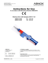
0,0
0,1
0,2
0,3
0,4
0,5
0,6
0,7
0,8
0,0 0,5 1,0 1,5 2,0 2,5 3,0
∆
p (bar)
∆pmax
∆p
“ ” (m
3
/h)
Bezeichnung:
D t i 812030 F i P HMD 1/( R )E
812031
Seite: 1/1
Zeichnungsnummer:
Legende:
“ ”
Volumenstrom Heizwasser in m
3
/
h
∆p freie Pressung (Werkseinstellung)
∆pmax freie Pressung maximal
Freie Pressung HMD 1/( R )E
812031
- /PEP 001-2012 / Liska / 23.05.2012
Änd./ÄM/Ersteller/Datum
Keys: UK812031
“” Volumetric ow of hot water
∆p Free compression (factory setting)
∆pmax Maximum free pressing
Free compression HMD 1/(R)E
/