KitchenAid KSCS25FVBT03 Installation guide
- Type
- Installation guide

INSTALLATION INSTRUCTIONS
IMPORTANT: READ AND SAVE THESE INSTRUCTIONS. INSTALLATION REQUIRES 2 OR MORE PEOPLE.
p
INSTRUCCIONES DE INSTALACION
IMPORTANTE: LEA Y GUARDE ESTAS INSTRUCCIONES. LA INSTALACION REQUIERE DE 20 MAS PERSONAS.
INSTRUCTIONS D'INSTALLATION
IMPORTANT : LIRE ET CONSERVER CES INSTRUCTIONS. L'INSTALLATION Nt_CESSITE
L'INTERVENTION DE 2 PERSONNES OU PLUS.
Table of Contents / Indice / Table des mati res
ASSISTANCE OR SERVICE ............................ 1
REFRIGERATOR SAFETY ............................... 2
INSTALLATION REQUIREMENTS ................. 2
Tools and Parts ............................................. 2
Product Dimensions ...................................... 2
Location Requirements ................................. 4
Electrical Requirements ................................ 4
Water Supply Requirements ......................... 5
INSTALLATION INSTRUCTIONS ................... 5
Unpack the Refrigerator ................................ 5
Install New Water Line .................................. 5
Connect Water Supply .................................. 6
Plug in Refrigerator ....................................... 7
Prepare the Water System ............................ 7
Level Refrigerator .......................................... 7
Door Height Adjustment ............................... 8
Complete Installation .................................... 8
AYUDA O SERVICIO TECNICO ...................... g
SEGURIDAD DEL REFRIGERADOR .............. 9
REQUISITOS DE INSTALACION .................... g
Piezas y herramientas ................................... 9
Medidas del producto ................................. 10
Requisitos de ubicacion .............................. 12
Requisitos el_ctricos ................................... 12
Requisitos del suministro de agua.............. 12
INSTRUCCIONES DE INSTALACli3N .......... 13
Desempaque el refrigerador ....................... 13
C6mo instalar una tuberia de agua nueva.. 13
Conexion del suministro de agua ............... 14
Como enchufar el refrigerador .................... 15
Preparaci6n del sistema de agua ............... 15
Como nivelar el refrigerador ....................... 15
Como ajustar la altura de la puerta ............. 16
Complete la instalaciOn ............................... 16
ASSISTANCE OU SERVICE .......................... 17
S¢CURITF: DU RCFRIGCRATEUR ................ 17
EXIGENCES D'INSTALLATION .................... 17
Outillage et pieces ....................................... 17
Dimensions du produit ................................ 18
Exigences d'emplaoement ......................... 20
Sp4cifications 41eotriques ........................... 20
Sp4cifications de I'alimentation en eau ...... 20
INSTRUCTIONS D'INSTALLATION ............. 21
D4ballage du r4frig4rateur .......................... 21
Installation d'une nouvelle
canalisation d'eau ....................................... 21
Raccordement a la canalisation d'eau ....... 22
Brancher le r4frig4rateur ............................. 23
Pr4parer le systeme d'eau .......................... 23
Nivellement du r4frig4rateur ........................ 23
Ajustement de la hauteur des portes .......... 24
Achever I'installation ................................... 24
Assistance or Service
If You Have Questions
If you have questions about operating, cleaning or maintaining
your refrigerator, see the Use & Care Guide.
If You Need Service
Maintain the quality built into your refrigerator by calling an
authorized service company.
To locate an authorized service company, see the Use & Care
Guide for the number to call, phone the dealer from whom you
purchased the refrigerator, or check the yellow pages of your local
phone directory.
Keep this book and your sales slip together for future
reference. You must provide proof of purchase or installation
date for in-warranty service.
Write down the following information about your appliance to help
you obtain assistance or service if you ever need it. You will need
to know your complete model number and serial number. You can
find this information on the model and serial number label, located
on the inside wall of the refrigerator compartment.
Dealer name
Serial number
Address
Phone number
Model number
Purchase date
2318510

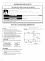
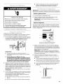
REFRIGERATOR SAFETY
Your safety and the safety of others are very important.
We have provided many important safety messages in this manual and on your appliance. Always read and obey all safety
messages.
This is the safety alert symbol.
This symbol alerts you to potential hazards that can kill or hurt you and others.
All safety messages will follow the safety alert symbol and either the word "DANGER" or "WARNING."
These words mean:
You can be killed or seriously injured if you don't immediately
follow instructions.
You can be killed or seriously injured if you don't follow
instructions.
All safety messages will tell you what the potential hazard is, tell you how to reduce the chance of injury, and tell you what can
happen if the instructions are not followed.
INSTALLATION REQUIREMENTS
IMPORTANT:
Observe all governing codes and ordinances.
Installer: Leave Installation Instructions with homeowner.
Homeowner: Keep Installation Instructions for future reference
and for the local electrical inspector's use.
• Keep cardboard shipping piece or plywood under refrigerator
until it is installed in the operating position.
• Comply with installation specifications and dimensions.
• Remove any moldings or decorative panels from kitchen
cabinets that prevent the refrigerator from being serviced.
• Contact a qualified electrical installer.
TOOLS NEEDED:
Gather the required tools and parts before starting installation.
Read and follow the instructions provided with any tools listed
here.
• Hand drill or electric drill • 7_6"and W' open-end
(properly grounded) wrenches
• W' nut driver and drill bit • Two adjustable
wrenches
• Flat-blade screwdriver
• s/_6"or adjustable wrench • 3/8"and W' socket
wrenches
PARTS NEEDED:
• Your refrigerator dealer has a kit available with a W' (6.35 ram)
saddle-type shutoff valve, a union, and copper tubing.
• Or you can purchase a W' (6.35 mm) copper tubing with
shutoff valve and a W' (6.35 ram) compression fitting
(coupling).
• Depending on water line connections, you may also need a %"
(6.35 ram) nut and Y4"(6.35 ram) ferrule.
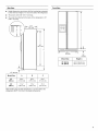
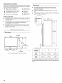
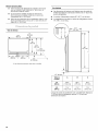
Top View
.,q(_m
N
35%" (95.3 ram)
(90.5o
1,-?
(39.6 cm) (49.5 cm) 25/8,, _'_A
(6.7 cm) max.
A. Dimensions may vary based on the model

Side View
• Height dimensions are shown with the leveling legs extended
to the minimum height of 1/4"(6.35 mm) below the refrigerator.
• The power cord is 66" (167.7 cm) long.
• The water line attached to the back of the refrigerator is 78"
(198.1 cm)long.
66"
(167.7 cm)
Front View
Model Size Height A
23' (654 L) 647/8'' (164.8 cm)
25' (694 L) 673/4'' (172.1 cm)
3%" (9.2 cm)
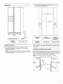
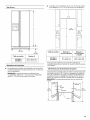
Model Size A B C
23' 68%" 687/8" 681/2''
(654 L) (174.6 cm) (175.0 cm) (174.0 cm)
25' 713/4'' 71%" 711/2''
(694 L) (182.2 cm) (182.5 cm) (181.6 cm)
When leveling legs are fully extended to 1" (25 mm) below the
refrigerator, add 3/4"(19 mm) to the height dimensions.

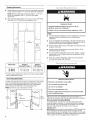
Opening Dimensions
• Height dimensions are shown with the leveling legs extended
to the minimum height of 1/4"(6.35 mm) below the refrigerator.
NOTE: When leveling legs are fully extended to 1" (25 mm)
below the refrigerator, add 3/4"(19 mm) to the height
dimensions.
• Minimum fixed wall position is 131/4'' (34 cm) from the freezer
door and 161/2'' (42 cm) from the refrigerator door.
(34 cm)
H
A
36"
(91.5 cm)
161/2 ''
(42 cm)
U
Explosion Hazard
Keep flammable materials and vapors, such as
gasoline, away from refrigerator.
Failure to do so can result in death, explosion, or fire.
NOTES:
• The cabinet depth refrigerator can be installed into a recessed
opening, at the end of cabinets or as a freestanding
refrigerator.
• If you are installing the refrigerator to fit flush with the front of
the base cabinets, all shoe molding and baseboards must be
removed from the rear of the refrigerator opening.
• For full-overlay cabinet doors, the height of the opening must
be 691/s'' (175.6 cm).
• Location should permit doors to open fully. See the "Door
Swing Dimensions" section.
• Do not install the refrigerator near an oven, radiator, or other
heat source, nor in a location where the temperature will fall
below 55°F (13°C).
• Floor must support refrigerator weight (more than 600 Ibs
[272 kg], door panels and contents).
Model Size Height A Height A
Standard Cabinet Full-overlay*
23' (654 L) 69" (175.3 cm) 691/8'' (175.6 cm)
25' (694 L) 72" (182.9 cm) 721/8'' (183.2 cm)
*For full-overlay cabinet doors with a trim kit, the opening height
must be adjusted as shown.
Door Swing Dimensions
Location must permit doors to open to a minimum of 150°. Allow
131/4'' (34 cm) minimum space between the side wall and the
freezer side of the refrigerator. Allow 161/2'' (42 cm) minimum
space between the side wall and the refrigerator side.
NOTE: Dimensions may vary based on model.
I II (8.8or,> 0" 4sl/2"
(14 "m) , [ (0.1m')l(11S.6o,)
Electrical Shock Hazard
Plug into a grounded 3 prong outlet.
Do not remove ground prong.
Do not use an adapter.
Do not use an extension cord.
Failure to follow these instructions can result in death,
fire, or electrical shock.
Before you move your refrigerator into its final location, it is
important to make sure you have the proper electrical connection.
Recommended Grounding Method
A 115 Volt, 60 Hz., AC only 15- or 20-amp fused, grounded
electrical supply is required. It is recommended that a separate
circuit serving only your refrigerator be provided. Use an outlet
that cannot be turned off by a switch. Do not use an
extension cord.
IMPORTANT: Ifthis product is connected to a GFCI (Ground Fault
Circuit Interrupter) protected outlet, nuisance tripping of the
power supply may occur, resulting in loss of cooling. Food quality
and flavor may be affected. If nuisance tripping has occurred, and
if the condition of the food appears poor, dispose of it.

NOTE:Beforeperforminganytypeofinstallation,cleaning,or
removingalightbulb,turnthecontrol(Thermostat,Refrigeratoror
FreezerControldependingonthemodel)toOFFandthen
disconnecttherefrigeratorfromtheelectricalsource.Whenyou
arefinished,reconnecttherefrigeratortotheelectricalsourceand
resetthecontrol(Thermostat,RefrigeratororFreezerControl
dependingonthemodel)tothedesiredsetting.
....,_ .... _ _ ©_.__V¸
Gather the required tools and parts before starting installation.
Read and follow the instructions provided with any tools listed
here.
TOOLS NEEDED:
• Flat-blade screwdriver • %" Drill bit
• 7/_6"and Y2"Open-end or two • Hand drill or electric drill
adjustable wrenches (properly grounded)
• Y," nut driver
NOTE: Your refrigerator dealer has a kit available with a %"
(6.35 mm) saddle-type shutoff valve, a union, and copper tubing.
Before purchasing, make sure a saddle-type valve complies with
your local plumbing codes. Do not use a piercing-type or 3/_6"
(4.76 mm) saddle valve which reduces water flow and clogs more
easily.
IMPORTANT:
• All installations must meet local plumbing code requirements.
• Use copper tubing and check for leaks. Install copper tubing
only in areas where the household temperatures will remain
above freezing.
Water Pressure
A cold water supply with water pressure of between 30 and
120 psi (207 - 827 kPa) is required to operate the water dispenser
and ice maker. Ifyou have questions about your water pressure,
call a licensed, qualified plumber.
Reverse Osmosis Water Supply
IMPORTANT: The pressure of the water supply coming out of a
reverse osmosis system going to the water inlet valve of the
refrigerator needs to be between 30 and 120 psi (207 - 827 kPa).
If a reverse osmosis water filtration system is connected to your
cold water supply, the water pressure to the reverse osmosis
system needs to be a minimum of 40 to 60 psi (276 to 414 kPa).
If the water pressure to the reverse osmosis system is less than
40 to 60 psi (276 to 414 kPa):
• Check to see whether the sediment filter in the reverse
osmosis system is blocked. Replace the filter if necessary.
• Allow the storage tank on the reverse osmosis system to refill
after heavy usage.
• If your refrigerator has a water filter, it may further reduce the
water pressure when used in conjunction with a reverse
osmosis system. Remove the water filter. See "Water Filtration
System" in the Use & Care Guide.
If you have questions about your water pressure, call a licensed,
qualified plumber.
INSTALLATION INSTRUCTIONS
Excessive Weight Hazard
Use two or more people to move and install
refrigerator.
Failure to do so can result in back or other injury.
Remove the Packaging
If the ice storage bin is located on the door, remove the temporary
shield from underneath the ice storage bin. See "Ice Maker and
Storage Bin."
Dispose of/recycle all packaging materials. Do not use sharp
instruments, rubbing alcohol, flammable fluids, or abrasive
cleaners to remove tape or glue. These products can damage the
surface of your refrigerator.
IMPORTANT:
• Use %" socket wrench to remove skids.
• All four leveling legs must contact the floor to support and
stabilize the full weight of the refrigerator.
Clean Before Using
After you remove all of the package materials, clean the inside of
your refrigerator before using it. See the cleaning instructions in
the Use & Care Guide.
Important information to know about glass shelves
and covers:
Do not clean glass shelves or covers with warm water when
they are cold. Shelves and covers may break if exposed to
sudden temperature changes or impact, such as bumping.
For your protection, tempered glass is designed to shatter
into many small, pebble-size pieces. This is normal. Glass
shelves and covers are heavy. Use special care when
removing them to avoid impact from dropping.
TOOLS NEEDED:
• Flat-blade screwdriver • _/4"Drill bit
• 7_6"and 1/2"Open-end or • Hand drill or electric drill
two adjustable wrenches (properly grounded)
When Moving Your Refrigerator:
Your refrigerator is heavy. When moving the refrigerator
for cleaning or service, be sure to protect the floor.
Always pull the refrigerator straight out when moving it.
Do not wiggle or "walk" the refrigerator when trying to move
it, as floor damage could occur.
1=
2.
Turn OFF main water supply. Turn ON nearest faucet long
enough to clear line of water.
Find a 1/2"(12.70 mm) to I_A'' (3.18 cm) vertical COLD water
pipe near the refrigerator.
NOTE: Horizontal pipe will work, but the following procedure
must be followed: Drill on the top side of the pipe, not the
bottom. This will help keep water away from the drill. This also
keeps normal sediment from collecting in the valve.

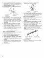
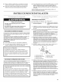
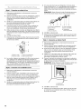
3. Determinethelengthofcoppertubingyouneed,Measure
fromtheconnectiononthelowerleftrearofrefrigeratortothe
waterpipe.Add7ft(2.1m)toallowforcleaning.Use1/4"
(6,35mm)O,D.(outsidediameter)coppertubing.Besureboth
endsofcoppertubingarecutsquare.
4. Usingagroundeddrill,drilla1/4"(6.35mm)holeinthecold
waterpipeyouhaveselected.
.................... A
G ........_.............B
A. Cold water pipe
B. Pipe clamp
C. Copper tubing
D. Compression nut
E. Compression sleeve
F. Shutoff valve
G. Packing nut
5. Fasten shutoff valve to cold water pipe with pipe clamp. Be
sure outlet end is solidly in the 1/4"(6.35 mm) drilled hole in the
water pipe and that washer is under the pipe clamp. Tighten
packing nut. Tighten the pipe clamp screws carefully and
evenly so washer makes a watertight seal. Do not overtighten
or you may crush the copper tubing, especially if soft (coiled)
copper tubing is used. Now you are ready to connect the
copper tubing.
6. Slip compression sleeve and compression nut on copper
tubing as shown in the diagram. Insert the end of the tubing
into the outlet end of the shutoff valve as far as it will go.
Screw the compression nut onto the outlet end with an
adjustable wrench. Do not overtighten.
7. Place the free end of the tubing into a container or sink, turn
ON main water supply and flush out tubing until water is clear.
Turn OFF the shutoff valve on the water pipe.
Style I - Connection to Water Valve
1. Unplug refrigerator or disconnect power.
2. Before attaching copper tubing to refrigerator, flush at least
2 qt (1.9 L) of water through the copper tubing and into a
bucket to get rid of any particles in the water line.
3. Check for leaks around the saddle valve. Do not overtighten
clamp or sleeve. This will crush copper tubing.
4. Attach the copper tube to the valve inlet using a compression
nut and sleeve as shown. Tighten the compression nut. Do not
overtighten.
5. Use the tube clamp on the back of the refrigerator to secure
the tubing to the refrigerator as shown. This will help prevent
damage to the tubing when the refrigerator is pushed back
against the wall.
6. Turn shutoff valve ON.
7,
Check for leaks. Tighten any connections (including
connections at the valve) or nuts that leak.
A. Tube clamp
B. Copper tubing
C. Compression nut
D. Valve inlet
8. The ice maker is equipped with a built-in water strainer. Ifyour
water conditions require a second water strainer, install it in
the 1/4"(6.35 mm) water line at either tube connection. Obtain
a water strainer from your nearest appliance dealer.
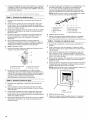
Style 2 - Connection to Water Line
1. Unplug refrigerator or disconnect power.
2. Remove and discard the shipping tape and the black nylon
plug from the gray, coiled water tubing on the rear of the
refrigerator.
3. Before attaching copper tubing to refrigerator, flush at least
2 qt (1.9 L) of water through the copper tubing and into a
bucket to get rid of any particles in the water line.
4. Check for leaks around the saddle valve. Do not overtighten
clamp or sleeve. This will crush copper tubing.
5. If the gray water tube supplied with the refrigerator is not long
enough, a 1/4"x 1/4"coupling is needed in order to connect the
water tubing to an existing household water line. Thread the
provided nut onto the coupling on the end of the copper
tubing.
NOTE: Tighten the nut by hand. Then tighten it with a wrench
two more turns. Do not overtighten.
6,
7.
A B C
A. Refrigerator water tubing
B. Nut (provided)
C. Bulb
D.Coupling (provided)
Turn shutoff valve ON.
Check for leaks. Tighten any nuts or connections (including
connections at the valve) that leak.
D E F G
E.Ferrule (purchased)
F. Nut (purchased)
G. Household water line

Style 3 - Connection to Shut-off Valve
1. Unplug refrigerator or disconnect power.
2. Remove and discard the shipping tape and the black nylon
plug from the gray, coiled water tubing on the rear of the
refrigerator.
3. Before attaching copper tubing to refrigerator, flush at least
2 qt (1.9 L) of water through the copper tubing and into a
bucket to get rid of any particles in the water line.
4. Check for leaks around the saddle valve. Do not overtighten
clamp or sleeve. This will crush copper tubing.
5. Push the bulb end of the tubing into the water valve as far as it
will go. Thread the provided nut onto the water valve as
shown.
NOTE: Tighten the nut by hand. Then tighten it with a wrench
two more turns. Do not overtighten.
Please read before using the water system.
Immediately after installation, follow the steps below to make sure
that the water system is properly cleaned.
1. Open the freezer door and turn off the ice maker. The On/Off
switch is located on the top right side of the freezer
compartment. Move the switch to the OFF (right) setting as
shown.
6.
7.
A
I/|
B
A.Bulb
B.Nut (provided)
Turn shutoff valve ON.
Check for leaks. Tighten any nuts or connections (including
connections at the valve) that leak.
_.,. ..............
Electrical Shock Hazard
Plug into a grounded 3 prong outlet.
Do not remove ground prong.
Do not use an adapter.
Do not use an extension cord.
Failure to follow these instructions can result in death,
fire, or electrical shock.
Plug into a grounded 3 prong outlet.
2.
3.
NOTES:
• Make sure the base grille filter is properly installed and the
cap is in the horizontal position.
• Do not use with water that is microbiologically unsafe
or of unknown quality without adequate disinfection
before or after the system. Systems certified for cyst
reduction may be used on disinfected waters that may
contain filterable cysts.
Use a sturdy container to depress the water dispenser bar
until the water begins to flow. Flush the water system by
dispensing and discarding 1.5 gal. (5.4 L) of water. Cleaning
the system will take approximately 3 minutes and will help
clear air from the line. Additional flushing may be required in
some households.
NOTE: As air is cleared from the system, water may spurt out
of the dispenser.
Open the freezer door and turn on the ice maker. Move the
switch to the ON (left) position. See the Use & Care Guide for
further instructions on the operation of your ice maker.
• Allow 24 hours to produce the first batch of ice.
• Discard the first three batches of ice produced.
• Depending on your model, you may want to select the
maximum ice feature to increase the production of ice.
IMPORTANT: All four leveling legs must contact the floor to
support and stabilize the full weight of the refrigerator.
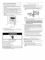
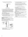
Remove the Base Grille
1. Open the refrigerator doors to 90°.
2. Remove base grille. Grasp the grille with both hands. Lift up
and tilt the top of the grille toward you.
NOTE: Do not remove the Tech Sheets fastened behind the
grille.

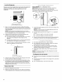
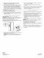
Level the Refrigerator
There is a set of two leveling bolts on each side of the refrigerator
behind the base grille. The top bolts adjust the rear of the
refrigerator, and the bottom bolts adjust the front of the
refrigerator.
A
B
m
E.__U
A.Rearleveling bolt (top)
B.Front leveling bolt (bottom)
1. Use a 1/2"(12.70 mm) socket wrench to adjust the leveling
bolts. Turn the leveling bolts to the right to raise or to the left to
lower the refrigerator. It may take several turns to adjust the tilt
of the refrigerator.
NOTE: Do not unscrew the leveling bolts too much when
lowering the refrigerator. The bolt head will start to come away
from the refrigerator when in the lowest position.
2. Adjust the front leveling bolts to bring the refrigerator top
parallel with the cabinet above the refrigerator.
• For standard cabinets, leave approximately 1/8"(3.18 mm)
gap between the refrigerator's top hinges and the
cabinets.
• For full-overlay cabinets, leave 1/4"(6.35 mm) gap between
the refrigerator's top hinges and the cabinets.
• Ifyou do not have a cabinet above the refrigerator, simply
adjust the refrigerator to make it level.
A. Top hinges
B. Front of the refrigerator
3. Adjust the rear leveling bolt to bring the refrigerator level with
the side cabinets or cabinet end panels.
4. If you want, you may now use the four leveling bolts to raise
the refrigerator to reduce the gap between the refrigerator top
hinge and the cabinet opening. Check that all four leveling
legs still touch the floor and that the cabinet doors above the
refrigerator open all the way.
Replace Base Grille
1. Open the refrigerator doors to 90°.
2. Replace the base grille. Place the lower clips into the bottom
of the refrigerator and roll the grille up until it snaps into place.
TOOLS NEEDED: _6" or adjustable wrench.
IMPORTANT: Models are preset with a quarter's-thickness
difference in door height and may not need adjusting.
If necessary after the refrigerator is loaded with food, follow the
steps below to adjust the door height up or down.
/ \
J
m
1. Locate the height adjustment bolt on the bottom hinge of the
refrigerator door.
NOTE: For easier access to the height adjustment bolt, the
refrigerator door should be closed.
2. Turn the height adjustment bolt using the _/16"or adjustable
wrench.
• To raise the height, turn the bolt to the right.
• To lower the height, turn the bolt to the left.
3. Check to make sure the doors are even at the top and bottom.
If necessary, continue to turn the height adjustment bolt.
1. Turn water supply line valve to "Open" position.
2. Turn refrigerator switch to ON position. Wait a few minutes.
Check water line connections for leaks.
3. Set refrigerator and freezer compartment controls to the
midpoint setting. Check that the compressor is operating
properly and that all lights are working.
4. Flush water system before using. See "Prepare the Water
System."
NOTE: If construction will continue after refrigerator has been
installed, set controls to OFR
If refrigerator does not operate
• Check that the circuit breaker is not tripped or household fuse
blown.
• Check that the power supply cord is plugged into a grounded
3 prong outlet.
• See "Troubleshooting" in the Use & Care Guide.
Page is loading ...
Page is loading ...
Page is loading ...
Page is loading ...
Page is loading ...
Page is loading ...
Page is loading ...
Page is loading ...
Page is loading ...
Page is loading ...
Page is loading ...
Page is loading ...
Page is loading ...
Page is loading ...
Page is loading ...
Page is loading ...
-
 1
1
-
 2
2
-
 3
3
-
 4
4
-
 5
5
-
 6
6
-
 7
7
-
 8
8
-
 9
9
-
 10
10
-
 11
11
-
 12
12
-
 13
13
-
 14
14
-
 15
15
-
 16
16
-
 17
17
-
 18
18
-
 19
19
-
 20
20
-
 21
21
-
 22
22
-
 23
23
-
 24
24


KitchenAid KSCS25FVBT03 Installation guide
- Type
- Installation guide
Ask a question and I''ll find the answer in the document
Finding information in a document is now easier with AI
in other languages
Related papers
-
Whirlpool KRSC500ESS Installation guide
-
Whirlpool KSBS25INSS03 Installation guide
-
Whirlpool KSBS23INBL00 Installation guide
-
KitchenAid KSSS42QTB04 Installation guide
-
-
KitchenAid KSCK23FV User manual
-
-
-
-
Other documents
-
Maytag 23inch User Instructions
-
Whirlpool WRS970CIDE Installation guide
-
-
-
Whirlpool WRS571CIHV Installation guide
-
Bauknecht GC3SHAXVS Owner's manual
-
-
Kenmore Elite 10645439800 Installation guide
-
Viking VCSF136D Installation guide
-
Jenn-Air JS42NXFXDW Installation guide