Miller FG6RA Installation guide
- Category
- Stoves
- Type
- Installation guide
This manual is also suitable for

!
WARNING:
Improper installation, adjustment, al-
teration, service, or maintenance can
cause injury or property damage. Refer
to this manual. For assistance or
additional information consult a quali-
fied installer, service agency, or the
gas supplier.
!
FOR YOUR SAFETY:
Do not store or use gasoline or other
flammable vapors and liquids in the vi-
cinity of this or any other appliance.
Residential Gas Furnaces
Installation Instructions
*RA Full Size Series 80+ High Efficiency Upflow/Horizontal
*RK Full Size Series 80+ High Efficiency Downflow
WHAT TO DO IF YOU
SMELL GAS:
• Do not try to light any appliance.
• Do not touch any electrical switch; do not
use any phone in your building.
• Immediately call your gas supplier from a
neighbor’s phone. Follow the gas supplier’s
instructions.
• If you cannot reach your gas supplier, call
the fire department.
• Extinguish any open flame.
*RA 80+ Upflow/Horizontal *RK 80+ Downflow
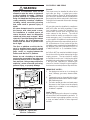
These instructions are primarily intended to assist qualified individuals experienced in the proper installation of
this appliance. Some local codes require licensed installation/service personnel for this type of equipment. Read
all instructions carefully before starting the installation.


Table of Contents
Furnace Specifications ................................................................................................................. 4-5
Upflow/Horizontal Models....................................................................................................... 4
Downflow Models.................................................................................................................... 5
Capacities-Furnace Airflow Data ........................................................................................6-7
Safety Information............................................................................................................................. 8
Installation Requirements ............................................................................................................ 8-9
Supply Air Plenum Installation ..................................................................................................... 10
Installation on a Concrete Slab ...........................................................................................10
Installation on a Combustible Floor .................................................................................... 10
Venting and Combustion Air Requirements................................................................................ 11
General ................................................................................................................................. 11
Installation in an Unconfined Space................................................................................... 11
Installation in a Confined Space ......................................................................................... 12
Horizontal Furnace Installation ................................................................................... 12
Air From Inside............................................................................................................. 13
Outdoor Air Using Vertical Ducts ................................................................................ 13
Air Directly Through an Exterior Wall.......................................................................... 13
Outdoor Air Using A Crawl Space and Ventilated Attic............................................ 14
Outdoor Air Through Horizontal Ducts .......................................................................14
Venting Requirements.................................................................................................................... 14
General ................................................................................................................................. 14
Category I - Common Venting ............................................................................................. 15
Category III - Horizontal Venting......................................................................................... 16
Horizontal Venting for Upflow Models ........................................................................ 16
Horizontal Venting for Downflow Models ................................................................... 17
Horizontal Power Venting ....................................................................................................18
Vent Termination Clearance ................................................................................................ 19
Location of Outdoor Terminations....................................................................................... 20
Horizontal Installation .................................................................................................. 20
Flexible Vent Systems .......................................................................................................... 21
Circulating Air Supply .................................................................................................................... 21
General ................................................................................................................................. 21
Return Air .............................................................................................................................. 21
Gas Supply and Piping .................................................................................................................. 22
General ................................................................................................................................. 22
Leak Check ........................................................................................................................... 22
Conversion ............................................................................................................................ 23
High-Altitude Application...................................................................................................... 23
Natural Gas High Altitude Conversion ................................................................................ 23
LP/Propane Gas Sea Level and High Altitude Conversion .........................................23-24
Electrical Wiring ............................................................................................................................. 25
General ................................................................................................................................. 25
Line Voltage Wiring .............................................................................................................. 25
Low Voltage Wiring............................................................................................................... 26
Start-up & Adjustments .................................................................................................................. 27
General ................................................................................................................................. 27
Start-Up Procedures.............................................................................................................27
Verifying and Adjusting Firing Rate .................................................................................... 27
Verifying and Adjusting Temperature Rise ....................................................................27-28
Verifying Burner Operation .................................................................................................. 29
Verifying Operation of Supply Air Limit Switch ................................................................... 29
Description of Components ........................................................................................................... 29
Wiring Diagram ................................................................................................................................ 30
Maintenance..................................................................................................................................... 31
Vent System.......................................................................................................................... 31
Air Filter(s).............................................................................................................................. 31
Lubrication ............................................................................................................................32
Blower Compartment ............................................................................................................ 32
Heat Exchanger and Burner Maintenance......................................................................... 32
Cleaning of Flue Passages ................................................................................................. 32
Cleaning of Burners .............................................................................................................33
System Operation Information ...................................................................................................... 33
General ................................................................................................................................. 33
Sequence of Operation ....................................................................................................... 33
Heating Mode............................................................................................................... 33
Cooling Mode ............................................................................................................... 34
Fan Mode ..................................................................................................................... 34
Furnace Fails to Operate .....................................................................................................34
Twinning ................................................................................................................................35
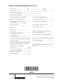
Installation/Performance Checklist ............................................................................................. 36

4
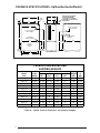
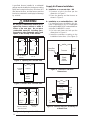
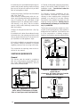
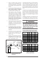
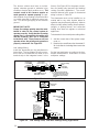
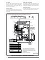
FURNACE SPECIFICATIONS - Upflow/Horizontal Models
Figure 1A. Upflow Unit Dimensions
Table 1A. Upflow Furnace Dimensions and Shipping Weights
Unit Shown in Upflow
Position Rotate 90˚
Clockwise or Counter
Clockwise for Horizontal
Application
23
3/
4
19
3/
4
3/4
43
25
1/
8
25
1
/4
25
5/
8
23
27
5
/8
15
20
1/
2
25
1/
4
33
30
1/
4
A
B
C
FLUE
OUTLET
1
1/
2
X 3
1/
2
Cut-out for
Gas Connection
3/4 3/4
1
1/
4
3/4
7/8 Cut-out for Electric
Connection
1
1/
2
X 3
1/
2
Cut-out for
Gas Connection
7/
8
Cut-out for
Electric Connection
Return
Air Opening
(Side)
1 1/4
1 1/4D
23
Return Air Opening
(Bottom)
7/8
Note: (*) Can be C or N
Furnace Dimensions Shipping
Model Input A B C Flue Outlet Weight D
*RA (Btuh) (in.) (in.) (in.) (in.) (lbs) (IN.)
045(*)-08 45,000 14 1/4 12 3/4 3 1/4 3 123 11 3/4
060(*)-12 60,000 14 1/4 12 3/4 3 3/4 4 134 11 3/4
072(*)-12 72,000 14 1/4 12 3/4 3 3/4 4 135 11 3/4
072(*)-16 72,000 19 3/4 18 1/4 3 3/4 4 152 17 1/4
072(*)-17 72,000 14 1/4 12 3/4 3 3/4 4 135 11 3/4
096(*)-12 96,000 19 3/4 18 1/4 3 3/4 4 163 17 1/4
096(*)-16 96,000 19 3/4 18 1/4 3 3/4 4 163 17 1/4
096(*)-20 96,000 22 1/2 21 3 3/4 4 174 20
120(*)-16 120,000 19 3/4 18 1/4 3 3/4 4 174 17 1/4
120(*)-20 120,000 22 1/2 21 3 3/4 4 182 20
144(*)-20 144,000 22 1/2 21 4 1/4 5 194 20
FURNACE DIMENSIONS AND
SHIPPING WEIGHTS

5
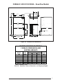
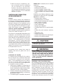
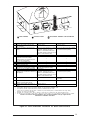
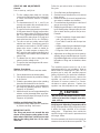
FURNACE SPECIFICATIONS - Downflow Models
Figure 1B. Downflow Unit Dimensions
Cut-out for Electric
Connection
Both sides
Cut-out for Gas Connection
1-1/2 x 3-1/2 (both sides)
27 7/8"
3/4"
23 5/8"
19 3/4"
3/4"
C
C
L
3/4"
3/4"
43"
4" Dia. Vent
Cut - out for
Gas Connection
A
B
B
25"
15 1/2"
27 1/8"
25"
3/4"
C
L
(Bottom Opening)
(Bottom Opening)
10 1/4"
24 1/2"
19 3/4"
Table 1B. Downflow Furnace Dimensions and Shipping Weights
Model Furnace Shipping
Number Input A B C Weights
*RK (Btuh) inches inches inches (lbs)
060(*)-12 60,000 14 1/4 12 3/4 5 1/2 134
072(*)-12 72,000 14 1/4 12 3/4 5 1/2 135
072(*)-16 72,000 19 3/4 18 1/4 11 147
096(*)-12 96,000 19 3/4 18 1/4 11 154
096(*)-16 96,000 19 3/4 18 1/4 11 156
120(*)-20 120,000 19 3/4 18 1/4 11 182
135(*)-20 135,000 19 3/4 18 1/4 11 182
DOWNFLOW FURNACE MODELS
FURNACE DIMENSIONS AND
SHIPPING WEIGHTS
Dimensions
Note: (*) Can be C or N

6
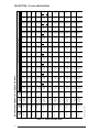
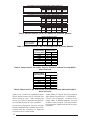
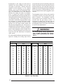
CAPACITIES —Furnace Airflow Data
Table 2. Furnace Airflow Data
† Can be C or N.
80+ UPFLOW/HORIZONTAL FURNACE MODELS
Model Heating
Number Input Motor Motor 0.1 0
.
*RA- (Btuh) Speed HP CFM Rise CFM
High * 1000 - 970
045(†)-08A 45,000 Medium 1/5 760 45 740
Low ** 630 54 620
High * 1380 - 1350
060(†)-12A 60,000 Medium 1/3 1220 - 1190
Low ** 820 55 800
High * 1380 - 1350
072(†)-12A 72,000 Medium 1/3 1220 45 1190
Low ** 820 66 800
High * 1980 - 1910
072(†)-16B 72,000 Med-High 1/2 1710 - 1660
Med-Low 1490 - 1470
Low ** 1270 43 1250
High *** 1950 1900
072(†)-17A
72,000 Med-High 3/4 1500 1450
Med-Low 1160 47 1130
Low **** 910 60 870
High * 1530 - 1450
096(†)-12B 96,000 Medium ** 1/3 1380 52 1320
Low 930 78 900
High * 1980 - 1910
096(†)-16B 96,000 Med-High 1/2 1720 - 1670
Med-Low ** 1470 - 1440
Low 1270 57 1240
High * 2340 - 2290
096(†)-20C 96,000 Med-High 3/4 1910 - 1880
Med-Low 1520 48 1510
Low ** 1370 53 1350
High * 1900 - 1830
120(†)-16B 120,000 Med-High** 1/2 1720 53 1670
Med-Low 1450 62 1420
Low 1260 72 1230
High * 2300 - 2250
120(†)-20C 120,000 Med-High 3/4 1910 47 1880
Med-Low ** 1540 59 1530
Low 1320 69 1310
High * 2240 49 2190
144(†)-20C 144,000 Med-High** 3/4 1900 57 1860
Med-Low 1520 71 1510
Low 1330 - 1310
External Static Pressure (Inches Water Column)
.2
0.3 0.4 0.5 0.6 0.7 0.8
Rise CFM Rise CFM Rise CFM Rise CFM Rise CFM Rise CFM Rise
- 950 - 920 - 870 - 820 - 770 - 700 49
46 730 47 720 47 690 49 670 51 640 53 620 55
55 610 56 600 57 570 60 540 63 510 67 470 72
- 1310 - 1260 - 1210 - 1150 - 1080 - 1000 45
- 1160 - 1120 - 1070 - 1020 - 950 48 880 51
57 780 58 760 60 730 62 700 65 670 68 640 71
- 1310 - 1260 - 1210 45 1150 47 1080 50 1000 54
46 1160 47 1120 49 1070 51 1020 53 950 57 880 62
68 780 70 760 71 730 74 700 - 670 - 640 -
- 1830 - 1760 - 1660 - 1570 - 1460 - 1350 40
- 1610 - 1540 - 1470 - 1390 - 1300 42 1200 45
- 1420 - 1380 - 1320 41 1250 43 1170 46 1090 50
43 1230 44 1190 46 1140 48 1080 50 1010 54 920 59
1810 1810 1770 1730 1700 1670
1420 1380 1340 1310 1280 1250
48 1090 50 1060 51 1030 53 980 55 940 58 900 60
62 840 64 810 67 770 70 740 73 710 680
50 1390 52 1300 56 1220 59 1130 64 1040 70 940 77
55 1250 58 1190 61 1100 66 1020 71 920 79 820 -
80 870 - 820 - 750 - 670 - 580 - 470 -
- 1840 - 1760 - 1680 - 1590 - 1500 - 1410 51
- 1610 - 1560 - 1480 - 1410 51 1320 55 1230 59
50 1410 51 1370 53 1320 55 1270 57 1200 60 1130 64
58 1220 59 1190 61 1140 64 1090 66 1040 70 970 75
- 2280 - 2180 - 2150 - 2080 - 2000 - 1920 -
- 1860 - 1830 40 1810 40 1790 40 1770 41 1750 41
48 1490 49 1480 49 1460 50 1440 50 1420 51 1400 52
54 1340 54 1320 55 1300 56 1280 57 1260 57 1230 59
- 1750 52 1630 56 1580 57 1490 61 1400 65 1320 69
54 1610 56 1560 58 1480 61 1410 64 1320 69 1230 74
64 1380 66 1340 68 1280 71 1220 74 1150 79 1070 -
74 1200 75 1170 77 1120 - 1070 - 1020 - 960 -
- 2190 - 2130 - 2090 - 2040 - 2000 45 1950 46
48 1860 49 1830 49 1800 50 1770 51 1740 52 1700 53
59 1520 60 1500 60 1480 61 1450 62 1420 64 1390 65
69 1300 70 1280 71 1260 72 1230 74 1200 75 1170 -
50 2130 51 2070 52 2020 54 1960 55 1910 57 1850 59
58 1820 60 1780 61 1740 62 1700 64 1660 65 1620 67
72 1490 73 1480 73 1450 75 1420 - 1390 - 1360 -
- 1290 - 1280 - 1250 - 1230 - 1210 - 1180 -

7
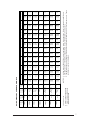
Table 2A. Furnace Airflow Data
** Factory Set Cooling Speed
** Factory Set Heating Speed
- Not Recommended
NOTES: 1. Airflow rates of 1800 CFM or more require two return air connections. Data is for operation with filter(s).
2. Temperature rises in the table are approximate. Actual temperature rises may vary.
3. Temperature rises and airflows for external static pressures greater than 0.5 are for reference only. These
conditions are not recommended.
80+ DOWNFLOW FURNACE MODELS
† Can be C or N.
MODEL
NUMBER HEATING MOTOR MOTOR
*RK INPUT SPEED HP
HIGH*
060(†)-12A
60,000 MEDIUM 1/3
LOW**
HIGH*
072(†)-12A
72,000 MEDIUM 1/3
LOW**
HIGH*
072(†)-16B
MED-HIGH 1/2
72,000 MED-LOW
LOW**
HIGH*
096(†)-12B
96,000 MEDIUM** 1/3
LOW
HIGH*
MED-HIGH 1/2
096(†)-16B
96,000 MED-LOW**
LOW
HIGH*
120(†)-20B
MED-HIGH 3/4
120,000 MED-LOW**
LOW
HIGH*
135(†)-20B
MED-HIGH** 3/4
135,000 MED-LOW
LOW
CFM Rise CFM Rise CFM Rise CFM Rise CFM Rise CFM Rise CFM Rise CFM Rise
1380 - 1345 - 1330 - 1260 36 1230 37 1190 38 1160 39 1120 40
118038114540113040111041108042106043104044101045
830 55 810 56 805 56 795 57 780 58 770 59 760 60 750 60
1380 - 1345 - 1330 - 1260 - 1230 - 1190 46 1160 47 1120 49
118046114547113048111049108050106051104052101054
830 65 810 67 805 67 795 68 780 70 770 71 760 71 750 72
1850 - 1790 - 1775 - 1755 - 1735 - 1700 - 1680 - 1650 -
1460 - 1435 38 1420 38 1400 39 1380 39 1360 40 1340 41 1320 41
121045119545118046116047114048112049111049109050
1020 53 1010 54 995 55 975 56 955 57 940 58 930 58 910 60
147549146050144550143051141051140052138052136053
120060119561118061116562114563114064112065111065
795 - 785 - 770 - 755 - 735 - 720 - 710 - 690 -
1950 - 1890 - 1865 - 1835 - 1805 40 1770 41 1730 42 1700 43
160045158046155547152548149548147049145050142051
137553136053133554130556127557125058123059120060
1180611165621140641110651080671060681030701010 -
2440 - 2395 - 2385 - 2375 - 2360 - 2340 - 2320 - 2300 -
192047191047190048189048187548187048186049184049
163056162056161056160057158557158057157058155058
143063142564141564140564139065138066137066136067
244041239542238542237542236042234043232043230044
192051191052190052189053187553187053186054184055
163061162062161062160063158563158063157064155065
1430691425701415701405 - 1390 - 1380 - 1370 - 1360 -
EXTERNAL STATIC PRESSURE (INCHES OF WATER COLUMN)
0.1 0.2 0.3 0.4 0.5 0.6 0.7 0.8

8
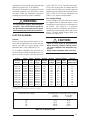
SAFETY INFORMATION
1. Use only with type of gas approved for this
furnace. Refer to the furnace rating plate.
2. Install this furnace only in a location and position
as specified on Table 3 of these instructions.
3. Provide adequate combustion and ventilation
air to the furnace space as specified on Pages
11 through 18.
4. Combustion products must be discharged
outdoors. Connect this furnace to an approved
vent system only, as specified on Pages 14
through 18.
5. Never test for gas leaks with an open flame. Use
a commercially available soap solution made
specifically for the detection of leaks to check
all connections, as specified on Page 21 of
these instructions.
6. Always install furnace to operate within the
furnace’s intended temperature-rise range with
a duct system which has an external static
pressure within the allowable range, as speci-
fied on Table 2 of these instructions. See
furnace rating plate.
7. When a furnace is installed so that supply ducts
carry air circulated by the furnace to areas
outside the space containing the furnace, the
return air shall also be handled by duct(s)
sealed to the furnace casing and terminating
outside the space containing the furnace.
8. A gas-fired furnace for installation in a
residential garage must be installed as
specified on Page 9 of these instructions.
9. The furnace is not to be used for temporary
heating of buildings or structures under con-
struction.
INSTALLATION REQUIREMENTS
Requirements and Codes
This furnace must be installed in accordance
with these instructions, all applicable local build-
ing codes, current revision of the National Fuel
Gas Code (ANSI-Z223.1), and in Canada with
the CAN/CGA - B149 installation code. The
current revision of the National Fuel Gas Code
is available from:
American National Standards Institute, Inc.
1430 Broadway
New York, New York 10018
Additional helpful publications are:
NFPA-90A - Installation of
Air Conditioning and Ventilating Systems
NFPA-90B - Warm Air Heating
and Air Conditioning Systems
These publications are available from:
National Fire Protection Association, Inc.
Batterymarch Park
Quincy, Massachusetts 02269
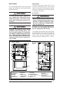
!
WARNING:
This furnace is not approved for installa-
tion in mobile homes. Installation in a
mobile home could cause fire, property
damage, and/or personal injury.
Location
Upflow gas furnaces are shipped ready for
installation in the upflow or horizontal right or left
positions. The *RK gas furnace is for downflow
operation only. The furnace must be installed on
a level surface, located as close to the vent (or
chimney) and as close to the center of the air
distribution system as possible. See Table 1 for
overall dimensions to determine the required
clearances in hallways, doorways, stairs, etc.
to allow the furnace to be moved to the instal-
lation point. The furnace must be installed so
that all electrical components are protected
from water. The furnace must be installed
upstream from a refrigeration system. This
furnace is not to be used for temporary heating
of buildings or structures under construction.
Clearances to Combustibles
This furnace is Design Certified by CSA Inter-
national for the minimum clearances to com-
bustible material listed in Table 3. Refer to the
furnace rating plate, located inside of the fur-
nace cabinet, for the specific model number and
clearance information.
Access for positioning and servicing the unit
must be considered when locating unit. 24
inches is the minimum required clearance from
the front of the unit for servicing it. 30 inches is
the minimum required clearance from the front
of the unit for positioning it. 36 inches is the
recommended clearance from the front of
the unit. Please note that a panel or door can
be located such that the minimum clearance on
the rating plate is satisfied, but that panel or door
must be removable and allow the appropriate
clearance for your installation.
This furnace is certified for use on wood floor-
ing. This furnace must not be installed directly
on carpeting, tile, or any combustible material
other than wood flooring.

9
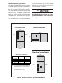
Table 3. Minimum Clearances to Combustible Material
LEFT
SIDE
BOTTOM
TOP
RIGHT
SIDE
Downflow Furnace Models
** For Downflow furnace installations only, furnace
must be installed on non-combustible flooring.
*** Allow 24" minimum clearance for servicing. The
recommended clearance is 36".
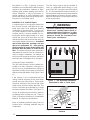
Downflow Warning (*RK Models):
The design of the downflow furnace is certified
for natural or propane gas and for installation on
non-combustible flooring. A special combus-
tible floor sub-base is required when installing
on a combustible floor. Failure to install the sub-
base may result in fire, property damage and
personal injury. The special downflow sub-
bases are factory supplied accessories, part
number 904165. When the furnace is installed
on a factory or site-built cased air conditioning
coil, the sub-base is not necessary. However,
the plenum attached to the coil casing must be
installed such that its surfaces are at least 1"
from combustible construction.
!
CAUTION:
The downflow sub-base must not be
installed directly on carpeting, tile, or any
combustible material other than wood
flooring.
LEFT
SIDE
RIGHT
SIDE
Upflow Furnace Models
BOTTOM
UPFLOW APPLICATION
TOP
TOP
HORIZONTAL APPLICATION
BOTTOM
SIDE
SIDE
Vent Connector
Type
Standard Single
Wall Metal Vent
Type B-1 Double
Wall Metal Vent
LEFT SIDE
0" 0"
RIGHT SIDE
0" 0"
VENT
6" 1"
BACK
0" 0"
BOTTOM
0"** 0"**
TOP
1" 1"
FRONT
4"*** 4"***
INSTALLATION CLEARANCES

10
A gas-fired furnace installed in a residential
garage must be installed so the burners and the
igniter are located not less than 18 inches (457
mm) above the floor, and the furnace must be
located or protected to avoid physical damage
by vehicles.
!
WARNING:
Do not place combustible material on or
against the furnace cabinet or within 6
inches of the vent pipe. Do not place
combustible materials, including gaso-
line and any other flammable vapors and
liquids, in the vicinity of the furnace.
Hole in
Floor
19.25"
18.75"
Hole in
Floor
19.25"
13.25"
*RK 072-16; 096-12;
096-16; 120-20
135-20;
*RK 060-12;
072-12
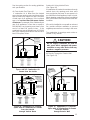
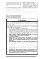
Figure 2. Opening for Concrete Slab
Figure 5. Downflow Sub-Base
Dimensions
Downflow
Wood
Sub-base
Floor
Furnace
Sheet
Metal
Plenum
Figure 6. Furnace with Coil Assembly on
a Wood Floor
Supply Air Plenum Installation
A. Installation on a concrete slab. - *RK
1. Construct a hole in the floor per the
dimension in Figure 2.
2. Place the plenum and the furnace as
shown in Figure 3.
B. Installation on a combustible floor. - *RK
For downflow furnace installation, this fur-
nace is approved for use on combustible
flooring when NORDYNE combustible floor
sub-base kit #904165 is used.
1. Cut hole and frame the hole per the
dimensions in Figure 4.
2. Install the sub-base according to the
installation instructions. (See Figure 5)
Wood
Floor
Coil
Assembly
Sheet
Metal
Plenum
Furnace
1"
Minimum
*RK 072-16;
096-12; 096-16;
120-20; 135-20
*RK 060-12;
072-12
Figure 4. Opening in Wood Floor
Concrete
Floor
Furnace
Sheet
Metal
Plenum
Figure 3. Furnace on a Concrete Slab
20.63"
18.75"
20.63"
13.25"
Hole in
Floor
Hole in
Floor

11
3. When the furnace is installed on a fac-
tory or site-built cased air conditioning
coil, the sub-base is not necessary.
However, the plenum attached to the
coil casing must be installed such that its
surface is at least 1” from combustible
material in Figure 6.
VENTING AND COMBUSTION
AIR REQUIREMENTS
General
Provisions must be made in the installation of
this furnace to provide an adequate supply of air
for combustion. Detailed instructions for deter-
mining the adequacy of an installation can be
found in the current revision of the National Fuel
Gas Code (ANSI Z223.1 / NFPA54) or in appli-
cable local building codes. Consult local
codes for special requirements. For Cana-
dian installations consult Canadian Installations
Codes and (CAN/CGA B149.1 or .2).
If the furnace is operated with inadequate air for
combustion one of the flame roll-out switches
located in the burner compartment or the vent
switch will open, turning off the gas supply to the
burners. These safety devices are manually
reset switches. DO NOT install jumper wires
across these switches to defeat their function.
DO NOT reset a switch without identifying and
correcting the fault condition. If a switch must be
replaced, use only the correct part specified in
the Replacement Parts List.
Air openings in the furnace door, warm air
registers, and return air grilles must not be
restricted.
Combustion Air Quality
To maximize heat exchanger life, the combus-
tion air must be free of chemicals which form
corrosive acidic compounds in the combustion
gases. The recommended source of combus-
tion air is to use the outdoor air supply. How-
ever, the use of indoor air in most applications
is acceptable except as follows:
1. If the furnace is installed in a confined space it
is recommended that the necessary combus-
tion air come from the outdoors by way of attic,
crawl space, air duct, or direct opening.
2. If outdoor combustion air is used, there must be
no exposure to the installations or substances
listed in Item 3 below.
3. The following types of installation may require
Outdoor Air for combustion, due to chemical
exposures:
• Commercial buildings
• Buildings with indoor pools
• Furnaces installed in laundry rooms
• Furnaces installed in hobby or craft rooms
• Furnaces installed near chemical storage
areas
Exposure to the following substances in the
combustion air supply may also require Out-
door Air for combustion:
• Permanent wave solutions
• Chlorinated waxes and cleaners
• Chlorine based swimming pool chemicals
• Water softening chemicals
• De-icing salts or chemicals
• Carbon tetrachloride
• Halogen type refrigerants
• Cleaning solvents (such as perchloroethyl-
ene)
• Printing inks, paint removers, varnishes,
etc.
• Hydrochloric acid
• Cements and glues
• Antistatic fabric softeners for clothes dryers
• Masonry acid washing materials
!
CAUTION:
Combustion air must not be drawn from
a corrosive atmosphere.
!
WARNING:
Furnace installation using methods other
than those described in the following
sections must comply with the National
Fuel Gas Code and all applicable local
codes to provide sufficient combustion
air for the furnace.
Installation In An Unconfined Space
An unconfined space is an area including all
rooms not separated by doors with a volume
greater than 50 cubic feet per 1,000 Btuh of the
combined input rates of all appliances which
draw combustion air from that space. For
example, a space including a water heater rated
at 45,000 Btuh input and a furnace rated at
75,000 Btuh requires a volume of 6,000 cubic
feet [50 x (45 + 75) = 6,000] to be considered
unconfined. If the space has an 8 foot ceiling,
the floor area of the space must be 750 square

12
feet (6,000 / 8 = 750). In general, a furnace
installed in an unconfined space will not require
outside air for combustion. However, in “tight”
buildings (with weather stripping and caulk to
reduce infiltration), it may be necessary to
provide outside air to ensure adequate com-
bustion and venting, even though the furnace is
located in an unconfined space.
Installation In A Confined Space
A confined space is an area with volume less
than 50 cubic feet per 1,000 Btuh of the com-
bined input rates of all appliances drawing
combustion air from that space. Furnace clos-
ets, small equipment rooms and garages are
confined spaces. Furnaces installed in a con-
fined space which supply heated air to areas
outside the space must draw return air from
outside the space and must have the return air
ducts tightly sealed to the furnace. A confined
space must have two openings into the
space for combustion air. One opening
must be within 12 inches of the ceiling, and
the other must be within 12 inches of the
floor. The required sizing of these openings is
determined by whether inside or outside air is
used to support combustion, the method by
which the air is brought to the space, and by the
total input rate of all appliances in the space.
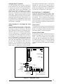
Horizontal Furnace Installation
The *RA series furnaces can be installed hori-
zontally in an attic, basement, crawl space or
alcove. It can be suspended from a ceiling in a
basement or utility room in either a right to left
airflow or left to right airflow. (See Figures 7 and
8.)
If the furnace is to be suspended from the
ceiling, it will be necessary to use steel straps
around each end of the furnace. These straps
should be attached to the furnace with sheet
metal screws and to the rafters with bolts. The
furnace could also be suspended by an angle
iron frame bolted to the rafters. (See Figure 7.)
Access for positioning and servicing must be
considered when locating the unit. Refer to
Table 3, Minimum Clearances to Combustible
Material, for clearance specifications.
Keep all insulating materials away from the
louvered door. Insulating materials may be
combustible.
The *RA series furnace may be installed di-
rectly on combustible wood flooring or sup-
ports, if type "B-1" vent pipe is used (See Figure
8). It is recommended for further reduction of
fire hazard that cement board or sheet metal be
placed between the furnace and the combus-
tible floor and extend 12 inches beyond the front
of the louvered door.
!
WARNING:
Furnaces installed with combustion air
drawn from a heated space which in-
cludes exhaust fans, fireplaces, or other
devices that may produce a negative
pressure should be considered con-
fined space installations.
Figure 7. *RA Horizontal Installation
Suspended in Attic or Crawl Space
Figure 8. *RA Horizontal installation on a
Platform
Gas Inlet
Electrical
Supply
Connection
Coil Plenum
Type “B” Vent
Combustible
Platform
Louver Door
Note: Line
Contact is Permissible

13
See the venting section for venting guidelines
and specifications.
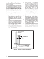
Air From Inside (See Figure 9)
If combustion air is taken from the heated
space, the two openings must
each
have a free
area of at least one square inch per 1,000 Btuh
of total input of all appliances in the confined
space, but not less than 100 square inches
of free area. For example, if the combined input
rate of all appliances is less than or equal to
100,000 Btuh, each opening must have a free
area of at least 100 square inches. If the
combined input rate of all appliances is 120,000
Btuh, each opening must have a free area of at
least 120 square inches.
Outdoor Air Using Vertical Ducts
(See Figure 10)
If combustion air is taken from outdoors through
vertical ducts, the openings and ducts must
have a minimum free area of one square inch
per 4,000 Btuh of total appliance input. In instal-
lations drawing combustion air from a ventilated
attic, both air ducts must extend above the attic
insulation.
If the unit is installed in an area with an exhaust
fan, provide sufficient ventilation to prevent
negative pressures from occurring in the room.
The combustion air openings must not be re-
stricted in any manner.
!
CAUTION:
Do not supply combustion air from an
attic space that is equipped with power
ventilation or any other device that may
produce a negative pressure.
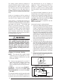
Air Directly Through An Exterior Wall
(See Figure 11)
Figure 11. Equipment in a Confined
Space with all Combustion Air Drawn
from the Outside
through Exterior Wall
Each opening
to outside
must be at least
1 sq. in. per 4000
Btuh of total input
rating.
12" Max
12" Max
Total Input
Rating (Btuh)
40,000
60,000
80,000
100,000
120,000
140,000
160,000
Minimum
Free Area
(Each Opening)
10 sq. in.
15 sq. in.
20 sq. in.
25 sq. in.
30 sq. in.
35 sq. in.
40 sq. in.
Round Duct
Diameter
4"
5"
5"
6"
6"
7"
8"
-
-
-
-
-
-
-
-
-
-
-
-
-
-
-
-
-
-
Furnace
Water Heater
Vent or
Chimney
Total Input
Rating (Btu/hr)
40,000
60,000
80,000
100,000
120,000
140,000
160,000
Minimum
Free Area
(Each Opening)
10 sq. in.
15 sq. in.
20 sq. in.
25 sq. in.
30 sq. in.
35 sq. in.
40 sq. in.
Round Duct
Diameter
4"
5"
5"
6"
6"
7"
8"
Inlet Air Duct must
be at least 1 sq. in.
per 4,000 Btuh of
total input rating.
Inlet and Outlet
Ducts must
extend above
attic insulation.
Outlet Air Duct must
be at least 1 sq. in.
per 4,000 Btuh of
total input rating.
Ventilation Louvers at
each end of attic
Attic
Insulation
12" Max
a. All Combustion Air from Ventilated Attic.
Furnace
Water Heater
Vent or
Chimney
Figure 10. Equipment in a Confined
Space with all Combustion Air Drawn
from the Outside
through Vertical Ducts
Total Input
Rating (Btu/hr)
40,000
60,000
80,000
100,000
120,000
140,000
160,000
Round Duct
Diameter
12"
12"
12"
12"
13"
14"
15"
Minimum
Free Area
(Each Opening)
100 sq. in.
100 sq. in.
100 sq. in.
100 sq. in.
120 sq. in.
140 sq. in.
160 sq. in.
Furnace
Openings to
adjacent space.
Each opening must
be at least 100 sq. in.
or 1 sq. in. per 1000
Btuh of total input
rating, whichever is
greater. See minimum
area per table.
12" Max.
12" Max.
Water Heater
Vent or
Chimney
Figure 9. Equipment in a Confined
Space with all Combustion Air
Drawn from the Inside

14
If combustion air is provided directly through an
exterior wall, the two openings must each have
free area of at least one square inch per 4000
Btuh of total appliance input.
Outdoor Air Using a Crawl Space and Ventilated
Attic (See Figure 12)
When directly communicating with the out-
doors, each opening shall have a minimum free
area of 1 square inch per 4,000 Btuh of total
appliance input. The openings shall communi-
cate directly, or by ducts, with the outdoor
spaces (crawl or attic) that freely communicate
with the outdoors.
Outdoor Air Using Horizontal Ducts (See Fig-
ure 13)
If combustion air is taken from outdoors through
horizontal ducts, the openings and ducts must
have a minimum free area of one square inch
per 2,000 Btuh of total appliance input.
If the unit is installed in an area with an exhaust
fan, provide sufficient ventilation to prevent
negative pressures from occurring in the room.
The combustion air openings must not be re-
stricted in any manner.
VENTING REQUIREMENTS
General
This furnace must be vented in compliance
with, the current revision of the National Fuel
Gas Code (ANSI-Z223.1/NFPA54), with the
instructions provided below.
Figure 12. Equipment in a Confined
Space with All Combustion Air Drawn
from a Crawl Space and Ventilated Attic
Outlet Air Duct
must be at least
1 sq. in. per 4000
Btuh of total input
rating. Must extend
above attic insulation.
Ventilation Louvers at
each end of attic
Attic Insulation
Ventilation Louvers for
unheated crawl space
Crawl Space
Inlet Air Duct must
be at least 1 sq. in.
per 4,000 Btuh of
total input rating.
Furnace
Water Heater
Vent or
Chimney
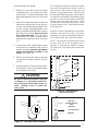
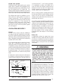
Figure 14. *RA Bleed Tube Installation
Collector
Pan
Pressure
Switch
Sensor
Tubes
Bleed Tube
Bleed Tube
Orifice - Pres
s
switch opera
t
at high altitu
d
can be made
responsive b
y
covering ble
e
orifice
Figure 13. Equipment in a Confined
Space with all
Combustion Air Drawn from the Outside
through Horizontal Ducts
Each opening
to outside
must be at least
1 sq. in. per 2000
Btuh of total input
rating.
12" Max
12" Max
Total Input
Rating (Btu/hr)
40,000
60,000
80,000
100,000
120,000
140,000
160,000
Minimum
Free Area
(Each Opening)
20 sq. in.
30 sq. in.
40 sq. in.
50 sq. in.
60 sq. in.
70 sq. in.
80 sq. in.
Round Duct
Diameter
5"
6"
7"
8"
9"
10"
10"
-
-
-
-
-
-
-
-
-
-
-
-
-
-
-
-
-
-
Furnace
Air Duct
Air Duct
Water Heater
Vent or
Chimney
-
-
-
-
-
-
-
-
-
-
-
-
-
-
-
-
-
-
-
-
-
-
-
-
-
-
-
-
-
-
-
-
-
-
-
-
In Canada, venting shall conform to the require-
ments of the current (CAN/CGA B149.1 or .2)
installation codes. Consult local codes for
special requirements.
For Category I furnace installations, the fur-
nace shall be connected to a factory built
chimney or vent complying with a recognized
standard, or a masonry or concrete chimney
lined with a lining material acceptance to the
authority having jurisdiction. Venting into an
unlined masonry chimney or concrete chim-
ney is prohibited.
This furnace must never be vented to a chim-
ney flue servicing a fireplace or other appliance
designed to burn solid fuel. If the furnace vent
is to be connected to a chimney serving a
fireplace, the fireplace must be sealed off from

15
the chimney. Single wall metal vents shall not be
used for Category I venting, Category I fur-
naces must be vented vertically or near verti-
cally.
The furnace vent, if metal, may be insulated if
local codes allow. Any part of the vent system,
metal vent only, not exposed to weather, but
which are exposed to ambient temperatures
below 35° F must be insulated to prevent con-
densation. All vent insulation shall be foil backed
fiberglass of one inch minimum thickness.
Three sheet metal fasteners (field supplied)
should be used to secure the vent pipe to the
furnace flue. These fasteners should be evenly
spaced around the flue diameter, if possible.
Category I - Common Venting
When an existing furnace is removed from a
venting system serving other appliances, the
venting system is likely to be too large to
properly vent the remaining appliances. An
improperly sized venting system can result in
the formation of condensate, leakage, spillage,
etc.
The steps outlined in the warning below shall be
followed with each individual appliance con-
nected to the vent system placed in operation,
while all other appliances connected to the vent
system are not in operation:
!
WARNING:
CARBON MONOXIDE POISONING HAZARD
Failure to follow the steps outlined below for each appliance connected to the
venting system being placed into operation could result in carbon monoxide
poisoning or death.
The following steps shall be followed for each appliance connected to the venting
system being placed into operation, while all other appliances connected to the
venting system are not in operation:
1. Seal any unused openings in the venting system.
2. Inspect the venting system for proper size and horizontal pitch, as required
in the
National Fuel Gas Code, ANSI Z223. 1/NFPA 54 or the CSA B149.1,
Natural Gas and Propane Installation Codes
and these instructions. Deter-
mine that there is no blockage or restriction, leakage, corrosion and other
deficiencies which could cause an unsafe condition.
3. As far as practical, close all building doors and windows and all doors
between the space in which the appliance(s) connected to the venting
system are located and other spaces of the building.
4. Close fireplace dampers.
5. Turn on clothes dryers and any appliance not connected to the venting
system. Turn on any exhaust fans, such as range hoods and bathroom
exhausts, so they are operating at maximum speed. Do not operate a summer
exhaust fan.
6. Follow the lighting instructions. Place the appliance being inspected into
operation. Adjust the thermostat so appliance is operating continuously.
7. Test for spillage from draft hood equipped appliances at the draft hood relief
opening after 5 minutes of main burner operation. Use the flame of a match
or candle.
8. If improper venting is observed during any of the above tests, the venting
system must be corrected in accordance with the
National Fuel Gas Code,
ANSI Z223.1/NFPA 54 and/or CSA B149.1, Natural Gas and Propane Installa-
tion Codes
.
9. After it has been determined that each appliance connected to the venting
system properly vents when tested as outlined above, return doors, win-
dows, exhaust fans, fireplace dampers and any other gas-fired burning
appliance to their previous conditions of use.

16
Figure 15. Vent Collar Detail
Cover
Plate
Nut
Covered Vent
Collar Hole
Figure 16. Limit Circuit Wiring
Wire Nut
Switch
Limit
Switch
Flame
Roll-Out
Switch
Vent
Limit
Blue
Blue
The venting system should be designed to
have the minimum number of elbows or turns.
All horizontal runs shall be sloped upwards
from the furnace at 1/4 inch per running foot of
vent. Supports for the vent pipe must be
installed a minimum of every five feet along the
vent run to ensure no displacement after instal-
lation.
Under no circumstances shall any portion of
the vent system extend into or pass through
any return air duct, supply air duct, or plenum.
If the furnace is operated with blocked or
restricted venting, the blocked vent switch
located in the vent plate will open, turning off the
gas supply to the burners. The blocked vent
switch is a manually reset device. DO NOT
install a jumper wire across this switch to defeat
its function. DO NOT reset the switch without
identifying and correcting the fault condition
which caused the switch to trip. If this switch
must be replaced, use only the part specified in
the Replacement Parts List.
!
WARNING:
Upon completion of the furnace installa-
tion, carefully inspect the entire flue sys-
tem both inside and outside the furnace
to assure it is properly sealed. Leaks in
the flue system can result in serious
personal injury or death due to exposure
of flue products, including carbon mon-
oxide.
Category III: Horizontal Venting
NOTE: The reduced NOx models (eighth
character N) are not approved as a Cat-
egory III (Category III) furnace for use with
horizontal venting.
The furnaces are approved for use with 3"
single wall AL29-4C stainless steel vent
pipe in horizontal vent applications. This
pipe is available from the following manufac-
turers:
Z-FLEX Inc. - vent brand name (Z-VENT)
Heat-fab Inc. - vent brand name (Saf-T Vent)
Flex-L International - vent brand name (Star-
34 Vent)
This vent pipe must be used for the entire length
of the vent run. The installation must be in
accordance with all instructions supplied by the
vent manufacturer for use on Category III
appliances. When venting horizontal, this is
defined as a Category III furnace, the vent
pressure is positive, and the venting system
must be sealed in both horizontal and vertical
runs.
For horizontal venting installations in both the
United States and Canada the transition as-
sembly must be modified by adding a bleed tube
to the pressure switch tube and bypassing the
vent switch. All model furnaces will require Vent
Kit #903196 for horizontal venting.
NOTE: No bleed tube is required for the *RA
045(C,N)-08 model.
Horizontal Venting For Upflow Models:
1. Remove the rubber tubing from the pressure
switch sensor tube and the collector pan sen-
sor tube. Cut 1/2 inch from one end of the rubber
sensor tube, fold in half and cut along the bend
line. Discard the 1/2 inch long piece of tubing.
Select the correct bleed tube using the table
supplied with vent kit #903196 and place the
other two pieces of tubing on both ends of the
bleed tube. Do not cover the hole in the bleed
tube. Place the assembly back on the pressure
switch sensor tube and the collector pan sen-
sor tube. (See Figure 14.)
2. Remove the nut and restrictor plate from the
vent collar assembly and discard the restrictor
plate. Select the appropriate dilution cover plate
as noted with vent kit #903196. Fit the clearance
hole in the cover plate over the weld stud. The
cover plate must cover the hole(s) on the vent
collar assembly. Tighten the nut securely while
holding the cover plate in position. (See Figure
15.)
3. Bypass the vent switch by removing both wires
from the vent switch and attaching them to the
wire nut. (See Figure 16.)

17
Figure 19. *RK Reducer Installation
Transition
4" to 3" Reducer
Special 3"
AL29-4C Stainless
Steel
Vent Pipe
Figure 18. *RK Horizontal
Vent Modification
Transition
Inducer
Remove
and
Discard
Combustion
Tube
Screw
Restrictor
Plate
The components of the horizontal vent system
must not be penetrated with screws, rivets, or
other devices, either when joining pipes and
fittings or using support straps. All joints must
be sealed with high temperature silicone before
locking bands are installed. If the lengths of pipe
must be cut, the joint must still be sealed with
silicone and the locking band used. When
installing the condensate tube be sure to form
a trap by means of a 3" loop filled with water.
(See Figure 20.)
Keep the number of pipe fittings to a minimum.
Maintain a minimum of 6 inches of air space
between the vent and combustibles at all times,
this includes inside and outside the building.
NOTE: The direction of the male-female joints
from the drain tee to the termination tee is
opposite to standard gas appliance venting.
The male end of the pipes point towards the
furnace.
Horizontal Venting: *RK Models:
1. By-pass the vent switch, located on blower
compartment door, by removing both wires
from the switch. Remove wire terminals, strip
wires and tie together in a wire nut. (See Figure
16.)
2. Remove the rubber tubing from the pressure
switch sensor tube and the collector pan sen-
sor tube. Cut the tubing approximately 3" from
one end. Select the appropriate dilution cover
plate as noted with vent kit #903196. Insert the
bleed tube into the tubing. Do not cover the
hole in the bleed tube. Place the tubing
assembly back on the pressure switch sensor
tube and collector pan sensor tube. (See Figure
17.)
3. To gain access to the restrictor plate, remove
and discard the combustion tube from the
transition assembly. Insure the seal between
inducer and transition assembly is not
broken. (See Figure 18.)
4. Remove and discard the restrictor plate and
screw from the transition assembly. (See Fig-
ure 18.)
5. Install and seal a 4" to 3" reducer to the transition.
(See Figure 19.) Attach the new high tempera-
ture vent pipe to the reducer.
Figure 17. *RK Bleed Tube Installation
Bleed Tube
Bleed Tube
Orifice
Collector
Pan
Pressure
Switch
!
CAUTION:
Do not drill holes through the vent pipe
or fittings on a horizontal vented fur-
nace. Do not use sheet metal screws, or
rivets. Drilling, screws, or rivets will
cause leaks.

18
90˚ Elbow
3" Dia. Loop
Outside
Wall
Wall Thimble
(For combustible
wall material)
Termination
Tee
Support
Tee
0-6'
Drain
Plug
1
/
4
" Per
Foot Rise
Locking Band
Locking
Band
Figure 20. Typical Horizontal Vent
Installation
1. Apply an adhesive bead around the
outside of the pipe approximately 1/4"
from the end of the pipe. This includes
the first fitting or pipe attached to the
furnace.
2. Push the pipe and fitting together while
twisting the pipe or fitting. Twisting the
pipe or fitting spreads the adhesive
completely within the fitting socket.
3. When the pipe is at the socket bottom,
inspect the joint. Look for a complete,
uninterrupted ring of adhesive material
around the pipe at the fitting socket.
Additional adhesive or rotation of the
pipe or fitting may be required for a
complete seal. The complete adhesive
material ring provides the seal required
for the positive pressure vent.
4. All vent systems must include a tee and
drain plug for collection and disposal of
condensate. The drain tee must be
installed within the first 5 feet of vent run
to protect the furnace.
5. All horizontal sections must have a
slope toward the drain tee of not less
than 1/4" per foot to prevent the collection
of condensate at any location other than
at the tee.
6. Horizontal runs must be supported with
3/4" pipe strap at a maximum of 5 foot
intervals and at each point where an
elbow is used.
7. Maintain a 6 inch minimum air space to
combustibles from all sections of the
stainless steel vent system, except
when a wall thimble is used.
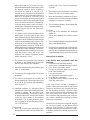
Horizontal Power Venting
— The Tjerlund GPAK-
1TN horizontal kit is certified for use with this
furnace. The kit includes a power venter, a side-
wall vent hood and a barometric draft control. It
has an electrical interlock to assure that the
furnace will not operate when the power venter
is off.
The kit is for use only when exhaust is through
an exterior wall, normally with horizontal vent
piping. The power venter establishes negative
pressure in the vent piping and the furnace
operates as if connected to Category I vertical
venting.
Installation Instructions are provided with the
kit. Installation must conform to those instruc-
tions and applicable requirements of local codes.
!
WARNING:
The entire vent system must be sealed
with a high temperature sealant which
will withstand temperatures of 450°F.
Recommended sealants: Dow Corning
Sealant 736 RTV; GE 106 RTV; High
Tech Ind., High TEMP RED.
Table 4. Horizontal
Venting Requirements
Horizontal Venting Requirements
Furnace
Model Number Pipe Reducer Maximum Max. Feet
*RA Size Needed # Elbows Vent Pipe
045C-08 3" None 4 35
060C-12 3" 4" to 3" 4 35
072C-12 3" 4" to 3" 4 35
072C-16 3" 4" to 3" 4 35
072C-17 3" 4" to 3" 4 35
096C-12 3" 4" to 3" 4 35
096C-16 3" 4" to 3" 4 35
096C-20 3" 4" to 3" 4 35
120C-16 3" 4" to 3" 4 35
120C-20 3" 4" to 3" 4 35
144C-20 3" 4" to 3" 3 30
Note: Special 5" to 4" Reducer Kit, p/n 902249 required for model
number *RA144C-20.
Furnace
Model Number Pipe Reducer Maximum Max. Feet
*R
K
Size Needed # Elbows Vent Pipe
060C-12 3" 4" to 3" 4 35
072C-12 3" 4" to 3" 4 35
072C-16 3" 4" to 3" 4 35
096C-12 3" 4" to 3" 4 35
096C-16 3" 4" to 3" 4 35
120C-20 3" 4" to 3" 4 35
135C-20 3" 4" to 3" 4 30

19
VENT TERMINAL
AIR SUPPLY INLET
AREA WHERE TERMINAL IS NOT PERMITTED
1
In accordance with the current CSA B149.1 Natural Gas and Propane Installation Code
2
In accordance with the current ANSI Z223.1 / NFPA 54 National Fuel Gas Code
† A vent shall not terminate directly above a sidewalk or paved driveway that is located between two single family
dwellings and serves both dwellings.
‡ Permitted only if veranda, porch, deck, or balcony is fully open on a minimum of two sides beneath the floor.
* For clearances not specified in ANSI Z223.1 / NFPA 54 or CSA B149.1, one of the following statement shall be included:
“Clearance in accordance with local installation codes, and the requirements of the gas supplier and the
manufacturer’s installation instructions.”
Figure 21. Vent Termination Clearances for Direct Vent Furnaces
Canadian Installations
1
US Installations
2
A =
Clearance above grade, veranda, porch,
deck, or balcony
12 inches (30 cm) 12 inches (30 cm)
B =
Clearance to window or door that may be
opened
6 inches (15 cm) for appliances
≤
10,000
Btuh (3 kW), 12 inches (30 cm) for
appliances > 10,000 Btuh (3 kW) and
≤
100,00 Btuh (30 kW), 36 inches (91 cm) for
appliances >100,00 Btuh (30 kW)
4 feet (1.2 m) below or to side of opening;
1 foot (300 mm) above opening
C =
Clearance to permanently closed window
**
D =
Vertical clearance to ventilated soffit
located above the terminal within a
horizontal distance of 2 feet (61 cm) from
the center line of the terminal
**
E =
Clearance to unventilated soffit
**
F =
Clearance to outside corne
r
**
G =
Clearance to inside corner
**
H =
Clearance to each side of center line
extended above meter/re
g
ulator assembl
y
3 feet (91 cm) within a height 15 feet
above the meter/re
g
ulator assembl
y
*
I =
Clearance to service regulator vent outlet 3 feet (1.83 m)
*
J =
Clearance to nonmechanical air supply inlet
to building or the combustion air inlet to any
other appliance
6 inches (15 cm) for appliances
≤
10,000
Btuh (3 kW), 12 inches (30 cm) for
appliances > 10,000 Btuh (3 kW) and
≤
100,00 Btuh (30 kW), 36 inches (91 cm) for
appliances >100,00 Btuh (30 kW)
4 feet (1.2 m) below or to side of opening;
1 foot (300 mm) above opening
K =
Clearance to a mechanical air supply inlet 6 feet (1.83 m) 3 feet (91 cm) above if within 10 feet (3 m)
horizontally
L =
Clearance above paved sidewalk or paved
driveway located on public property
7 feet (2.13 m) † 7 feet (2.13 m)
M =
Clearance under veranda, porch deck, or
balcony
12 inches (30 cm) ‡
*

20
Location of Outdoor Terminations
Horizontal Installation
The vent termination tee must be installed with
the following minimum clearances. (See Figure
21.) Vent termination clearances shall be con-
sistent with the
National Fuel Gas Code, ANSI
2223.1/NFPA 54 and/or the CSA B149.1,
Natural Gas and Propane Installation Code.
All minimum clearances specified must be
maintained to protect building materials from
degradation by flue gases.
1. The termination tee must be 12 inches
above snow level or grade level which
ever is higher. See Figure 22 for alter-
nate method to achieve 12" above snow
level.
2. Avoid areas where condensate drainage
may cause problems such as above
planters, patios, or adjacent to windows
where the steam from the flue gases
may cause fogging. Do not terminate
above any public walkway.
3. Select the point of wall penetration where
the minimum 1/4 inch per foot of upward
slope can be maintained.
4. When penetrating a noncombustible
wall, the hole through the wall must be
large enough to maintain the pitch, pipe
clearance for passage, and provide for
proper sealing. Penetrating a combus-
tible wall requires the use of a wall
thimble. (See Figure 22.) A 6-1/2 inch
square framed opening is required to
insert the thimble halves. The thimble is
adjustable to varying wall thickness and
is held in place by applying sealant to the
male sleeve before assembly. Also run
a bead of sealant around the outer wall
thimble.
5. The vent pipe must extend 1-1/4 inches
through the outer thimble half for a
combustible wall. Be sure to check this
carefully before cutting the vent pipe.
6. Attach a 3 inch coupling to the end of the
pipe that extends through the wall or
thimble. This prevents the vent pipe
from being pushed inward.
7. Cut an 8 inch minimum piece of vent pipe
and connect the coupling to the
termination tee. The inside of the tee
must be a minimum of 12 inches from
the outside of the wall. (See Figure 23.)
Use Wall Thimble at
Vent Points
Support
Ground Level
Termination Tee
Figure 22. Alternate Horizontal Vent Installation
Page is loading ...
Page is loading ...
Page is loading ...
Page is loading ...
Page is loading ...
Page is loading ...
Page is loading ...
Page is loading ...
Page is loading ...
Page is loading ...
Page is loading ...
Page is loading ...
Page is loading ...
Page is loading ...
Page is loading ...
Page is loading ...
-
 1
1
-
 2
2
-
 3
3
-
 4
4
-
 5
5
-
 6
6
-
 7
7
-
 8
8
-
 9
9
-
 10
10
-
 11
11
-
 12
12
-
 13
13
-
 14
14
-
 15
15
-
 16
16
-
 17
17
-
 18
18
-
 19
19
-
 20
20
-
 21
21
-
 22
22
-
 23
23
-
 24
24
-
 25
25
-
 26
26
-
 27
27
-
 28
28
-
 29
29
-
 30
30
-
 31
31
-
 32
32
-
 33
33
-
 34
34
-
 35
35
-
 36
36


Miller FG6RA Installation guide
- Category
- Stoves
- Type
- Installation guide
- This manual is also suitable for
Ask a question and I''ll find the answer in the document
Finding information in a document is now easier with AI
Related papers
-
Intertherm RC 92+ User manual
-
Broan DGAA, DGAH, DGPH and DGPA Series Furnace - Evcon Installation guide
-
Westinghouse KG6RC Product information
-
Intertherm M3RL Product information
-
Intertherm M2 Installation guide
-
Intertherm M4RC-072D-35C Installation guide
-
Broan M4R(C,L) Installation guide
-
-
-
Broan R4GD 036K096 Installation guide
Other documents
-
Broan FG6RA Installation guide
-
Nordyne 120C-16 Installation Instructions Manual
-
Gibson FG6T(A,K) Installation guide
-
Trane Oxbox 14 Seer J4PG4030A1060AA Installation Instructions Manual
-
Broan PAH2BM Product information
-
-
Gibson KG6RC Installation guide
-
Whirlpool 187122 User manual
-
Weil-McLain All Furnace User manual
-
Lennox MERIT EL280DF110P60C User manual