
DOC022.97.80306
Lachat BD40
HT
06/2012, Edition 1
User Manual
Manuel d'utilisation
Manual del usuario
Manual do Usuário
用户手册
取扱説明書
사용 설명서
Page is loading ...

Table of contents
Specifications on page 3 Operation on page 11
General information on page 3 Maintenance on page 16
Installation on page 7 Troubleshooting on page 18
User interface on page 9 Replacement parts and accessories on page 19
Startup on page 11
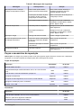
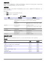
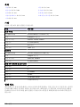
Specifications
Specifications are subject to change without notice.
Specification Details
Digestion block
Dimensions (W x D x H) 43 x 44 x 69 cm (17 x 17.5 x 27 in.)
Weight 20.9 kg (46.1 lb)
Power requirements 230 V ±5%, 3400 W, 50/60 Hz
Operating temperature Maximum 450 °C (842 °F)
Capacity 40 samples
Sample tube 115 mL capacity
Controller
Dimensions (W x D x H) 25 x 19 x 17 cm (9.8 x 7.5 x 6.8 in.)
Weight 2.2 kg (4.9 lb)
Power requirements 230 V ±10%, 50/60 Hz
Operating temperature Maximum 85 °C (185 °F)
Environmental specifications, controller and digestion block
Installation category II
Pollution degree 2
Altitude Up to 2000 m
Relative humidity 30% to 80%
Storage temperature –5 to 40 °C (23 to 104 °F)
Warranty 1 year from date of purchase
General information
In no event will the manufacturer be liable for direct, indirect, special, incidental or consequential
damages resulting from any defect or omission in this manual. The manufacturer reserves the right to
make changes in this manual and the products it describes at any time, without notice or obligation.
Revised editions are found on the manufacturer’s website.
English
3

Safety information
N O T I C E
The manufacturer is not responsible for any damages due to misapplication or misuse of this product including,
without limitation, direct, incidental and consequential damages, and disclaims such damages to the full extent
permitted under applicable law. The user is solely responsible to identify critical application risks and install
appropriate mechanisms to protect processes during a possible equipment malfunction.
Please read this entire manual before unpacking, setting up or operating this equipment. Pay
attention to all danger and caution statements. Failure to do so could result in serious injury to the
operator or damage to the equipment.
Make sure that the protection provided by this equipment is not impaired. Do not use or install this
equipment in any manner other than that specified in this manual.
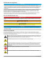
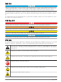
Use of hazard information
D A N G E R
Indicates a potentially or imminently hazardous situation which, if not avoided, will result in death or serious injury.
W A R N I N G
Indicates a potentially or imminently hazardous situation which, if not avoided, could result in death or serious
injury.
C A U T I O N
Indicates a potentially hazardous situation that may result in minor or moderate injury.
N O T I C E
Indicates a situation which, if not avoided, may cause damage to the instrument. Information that requires special
emphasis.
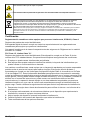
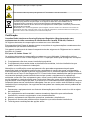
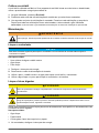
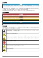
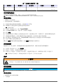
Precautionary labels
Read all labels and tags attached to the instrument. Personal injury or damage to the instrument
could occur if not observed. A symbol on the instrument is referenced in the manual with a
precautionary statement.
This is the safety alert symbol. Obey all safety messages that follow this symbol to avoid potential
injury. If on the instrument, refer to the instruction manual for operation or safety information.
This symbol indicates that a risk of electrical shock and/or electrocution exists.
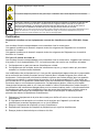
This symbol identifies the presence of a strong corrosive or other hazardous substance and a risk of
chemical harm. Only individuals qualified and trained to work with chemicals should handle chemicals
or perform maintenance on chemical delivery systems associated with the equipment.
This symbol indicates the need for protective eye wear.
This symbol indicates that the marked item can be hot and should not be touched without care.
4 English

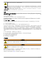
This symbol indicates that the object is heavy.
This symbol indicates the presence of toxic gas. Use of a fume hood is required.
Electrical equipment marked with this symbol may not be disposed of in European public disposal
systems after 12 August of 2005. In conformity with European local and national regulations (EU
Directive 2002/96/EC), European electrical equipment users must now return old or end-of-life
equipment to the Producer for disposal at no charge to the user.
Note: For return for recycling, please contact the equipment producer or supplier for instructions on how to return end-
of-life equipment, producer-supplied electrical accessories, and all auxiliary items for proper disposal.
Certification
Canadian Radio Interference-Causing Equipment Regulation, IECS-003, Class A:
Supporting test records reside with the manufacturer.
This Class A digital apparatus meets all requirements of the Canadian Interference-Causing
Equipment Regulations.
Cet appareil numèrique de la classe A respecte toutes les exigences du Rëglement sur le matériel
brouilleur du Canada.
FCC Part 15, Class "A" Limits
Supporting test records reside with the manufacturer. The device complies with Part 15 of the FCC
Rules. Operation is subject to the following conditions:
1. The equipment may not cause harmful interference.
2. The equipment must accept any interference received, including interference that may cause
undesired operation.
Changes or modifications to this equipment not expressly approved by the party responsible for
compliance could void the user's authority to operate the equipment. This equipment has been tested
and found to comply with the limits for a Class A digital device, pursuant to Part 15 of the FCC rules.
These limits are designed to provide reasonable protection against harmful interference when the
equipment is operated in a commercial environment. This equipment generates, uses and can
radiate radio frequency energy and, if not installed and used in accordance with the instruction
manual, may cause harmful interference to radio communications. Operation of this equipment in a
residential area is likely to cause harmful interference, in which case the user will be required to
correct the interference at their expense. The following techniques can be used to reduce
interference problems:
1. Disconnect the equipment from its power source to verify that it is or is not the source of the
interference.
2. If the equipment is connected to the same outlet as the device experiencing interference, connect
the equipment to a different outlet.
3. Move the equipment away from the device receiving the interference.
4. Reposition the receiving antenna for the device receiving the interference.
5. Try combinations of the above.
Product overview
W A R N I N G
Gas inhalation hazard. Operate the instrument in a fume hood to prevent exposure to hazardous gas.
English 5

W A R N I N G
Burn hazard. The digestion block gets extremely hot. Do not touch.
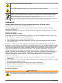
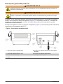
The BD40
HT
is a high-temperature block digestion system. A color touchscreen controller gives
power to the digestion block (Figure 1). The controller holds 12 test methods. The test methods
control test times and temperatures and can be modified as necessary.
The digestion block holds 40 digestion tubes (Figure 2). Samples can be heated to 450 °C.
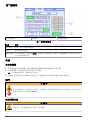
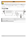
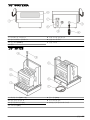
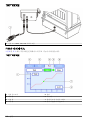
Figure 1 Touchscreen controller
1 Stylus for touchscreen 5 Power cable connection to digestion block
2 Color touchscreen interface 6 Power cord connector
3 Dongle port (COM 2) 7 Power switch
4 Dongle
6 English

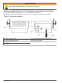
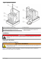
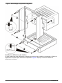
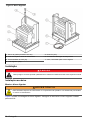
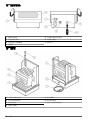
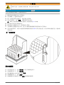
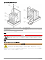
Figure 2 Digestion block
1 Graphite block (SiC coated) 5 Cold finger (40x)
2 Reaction tube and cooling rack 6 Temperature calibration connection
3 Heat deflector shield (2x) 7 Cable, controller to digestion block
4 Digestion tube (40x)
Installation
D A N G E R
Multiple hazards. Only qualified personnel must conduct the tasks described in this section of the
document.
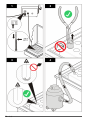
Mechanical installation
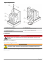
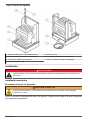
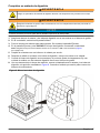
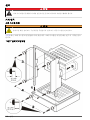
Assemble the digestion block
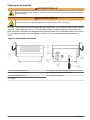
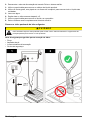
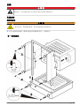
W A R N I N G
Personal injury hazard. Instruments or components are heavy. Use assistance to install or move.
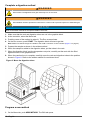
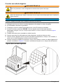
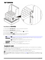
Figure 3 shows the assembly of the digestion block. Make sure to hold the digestion block by the
base to move it.
English
7


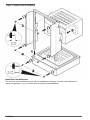
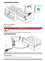
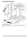
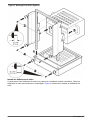
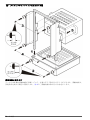
Figure 4 Heat deflector installation
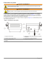
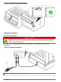
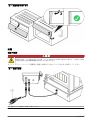
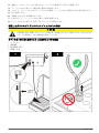
Electrical installation
Power connections
D A N G E R
Electrocution hazard. If this equipment is used outdoors or in potentially wet locations, a Ground Fault
Circuit Interrupt (GFCI/GFI) device must be used for connecting the equipment to its main power
source.
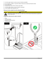
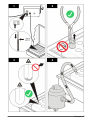
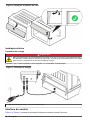
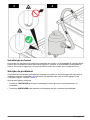
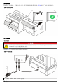
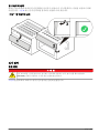
Refer to Figure 5 to connect the digestion block and controller to power.
Figure 5 Power connections
1 Power cord, 230 V, 15 A with C19 connector
User interface
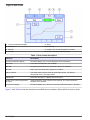
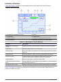
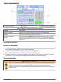
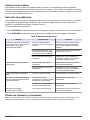
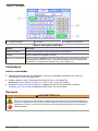
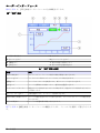
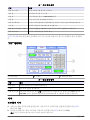
Figure 6 and Table 1 show the main functions of the Run screen interface.
English
9

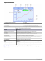
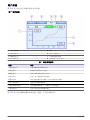
Figure 6 Run screen
1 Current temperature display 5 Alarm
2 Menu tab 6 Utilities tab
3 Edit tab 7 Graph of the current temperature and time
4 Run tab 8 Current time (time elapsed) display
Table 1 Run screen description
Function Description
Current temperature display Numerical display of the current digestion block temperature
Menu tab List of the test methods in the controller
Edit tab Change the parameters of a method and enter new methods
Run tab Start, stop and monitor the progress of a method
Alarm indicator The audio alarm is active when the green light shows. The alarm is
deactivated when a gray light shows.
Utilities tab Select the language or calibrate the touchscreen
Graph of the current temperature
and time
Graphical display of the progress of the method. The cursor shows the
progress of the method.
Current time display Numerical display of the amount of time the method has been in operation
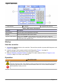
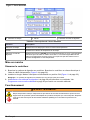
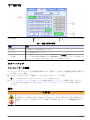
Figure 7 and Table 2 show the functions of the Edit screen interface. Select a field to enter a value.
10
English

Figure 7 Edit screen
1 Step selection 2 Keypad 3 Digestion tube selection
Table 2 Edit screen description
Function Description
Step selection Select a step to enter temperature information.
Keypad Enter the temperature and the time values.
Digestion tube selection Always select OTHER for glass digestion tubes.Teflon tubes have a maximum
temperature of 260 °C. DigiTUBE tubes are polypropylene single-use tubes and cannot
be used with the HT digestion block.
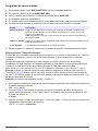
Startup
Start the controller
1. Connect the digestion block to the controller. Connect the controller to power with the power cord
(Figure 5 on page 9).
2. Install the dongle. Set the power switch to the ON position (Figure 1 on page 6).
Note: The digestion block will not get hot unless the dongle is installed.
3. Refer to Complete a digestion method on page 12 to start a method. Refer to Program a new
method on page 12 to enter a new method.
Operation
W A R N I N G
Chemical exposure hazard. Obey laboratory safety procedures and wear all of the personal protective
equipment appropriate to the chemicals that are handled. Refer to the current material safety data
sheets (MSDS) for safety protocols.
English 11

Complete a digestion method
W A R N I N G
Burn hazard. The digestion block gets extremely hot. Do not touch.
W A R N I N G
Gas inhalation hazard. Operate the instrument in a fume hood to prevent exposure to hazardous gas.
N O T I C E
Refer to the written method for the specific details of each test.
1. Make sure that the rack and digestion tubes are not in the graphite block.
2. At the controller, select the Menu tab.
3. Push the name of the method to select it. The Run screen shows.
4. On the Run screen, push START. The digestion block will start to get hot.
Note: Make sure that the dongle is installed in the COM 2 connector on the controller (Figure 1 on page 6).
5. Prepare the sample as shown in the written method.
6. When the sample is added to the digestion tubes, put the tubes in the rack.
7. When the digestion block is at the temperature set point, carefully set the rack with the filled
digestion tubes in the graphite block.
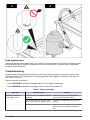
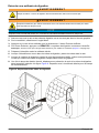
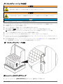
8. When the reaction time is complete, carefully move the rack and digestion tubes to the position
shown in Figure 8. Refer to the written method for cool-down times.
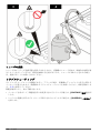
Figure 8 Move the digestion tubes
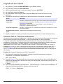
Program a new method
1. On the Menu tab, push NEW METHOD. The Edit tab opens.
12
English

2. On the Edit tab, push NEW METHOD.
3. Use the keyboard to enter the name of the method. Push ACCEPT.
4. On the Edit tab, push Step 1.
5. At the bottom of the Edit tab, push Other to select glass digestion tubes.
6. Refer to the written method instructions to find the necessary information.
Option Description
Time TO Temperature Range: 0 to 999 minutes. The time that the digestion block will use to get to the
temperature set point. Refer to Find the "Time to Temperature" value on page 13.
Note: Enter a value of "1" to get to the temperature set point as fast as possible.
Time AT Temperature Range: 0 to 999 minutes. The amount of time for the method to stay at the Step
1 set point.
Setpoint Temperature The temperature is defined by the written method.
7. Repeat steps 5 and 6 for methods with additional temperature reaction periods.
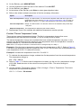
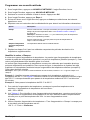
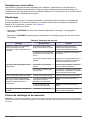
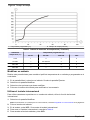
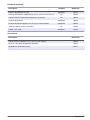
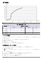
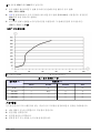
Find the "Time to Temperature" value
There are two types of temperature change. The first is a temperature change from room
temperature to an initial set point (Example 1). This is usually a look-up value.
The second temperature change is for methods that have multiple temperature set points. In this
scenario, the block temperature will be above room temperature when the temperature increase is
started (Example 2). This value must be calculated.
Note: Enter "0" to keep the controller on the edit screen or disregard Step 2 or Step 3.
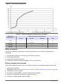
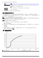
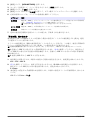
Example 1: Find the time to temperature value from room temperature to 250 °C. Refer to Figure 9.
Find where the temperature rate line crosses the 250 °C line. The minimum time to temperature from
room temperature to 250 °C is about 20 minutes.
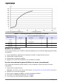
Example 2: Increase the temperature from 250 °C to 400 °C.
1. To calculate the temperature change, subtract the first temperature from the second temperature.
The temperature change is:
400 – 250 = 150 °C.
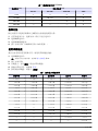
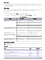
2. Refer to Table 3. To find the rate of temperature increase, use the row for a temperature change
of 25–200. Read the value in the column for a set point of 350+. The rate of change is:
3 °C/min
3. Use the equation Temperature change ÷ Rate of change = Time to Temperature. The time to
temperature for the second set point is:
150 °C ÷ 3 °C/min = 50 minutes.
English
13

Figure 9 Time to temperature
1 Setpoint temperature (°C) 2 Time to temperature (minutes)
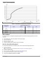
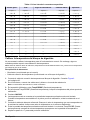
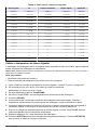
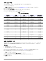
Table 3 Temperature increase rates (°C/minute)
Temperature
change (°C)
Set point temperature (°C)
25–50 50–225 225–350 350+
0–25 1 3 2 2
25–200 — 20 minutes 4 3
200–325 — — 8 4
325–425 — — — 5
Edit a method
Do this procedure to change the temperature profile of a method already programmed into the
controller.
1. On the Menu tab, select the method. The Run tab opens.
2. Select the Edit tab.
3. Select the options to edit.
4. Push the method name to edit the name if necessary.
Use the international keyboard
To use special characters in a method name, use the international keyboard function.
1. Select the Edit tab.
Note: To enter a name for a new method, refer to Program a new method on page 12.
2. Push the method name.
3. On the keypad, push INTL. The international keyboard shows.
4. To make an international character, refer to Table 4.
5. To go to the standard keyboard, push INTL.
14
English

Table 4 How to enter special characters
Grave Tilde Caret Double quote Apostrophe
` + space = ` ~ + space = ~ ^ + space = ^ " + space = " ' + space = '
` + E = È ~ + O = Õ ^ + E = Ê " + E = Ë ' + C = Ç
` + U = Ù ~ + N = Ñ ^ + U = Û " + U = Ü ' + E = É
` + I = Ì ~ + A = Ã ^ + I = Î " + I = Ï ' + Y = Ý
` + O = Ò ~ + o = õ ^ + O = Ô " + O = Ö ' + U = Ú
` + A = À ~ + n = ñ ^ + A = Â " + A = Ä ' + I = Í
` + e = è ~ + a = ã ^ + e = ê " + e = ë ' + O = Ó
` + u = ù ~ + x = ~x ^ + u = û " + y = ÿ ' + A = Á
` + i = ì — ^ + i = î " + u = ü ' + c = ç
` + o = ò — ^ + o = ô " + i = ï ' + e = é
` + a = à — ^ + a = â " + o = ö ' + y = ý
` + x = `x — ^ + x = ^x " + a = ä ' + u = ú
— — — " + x = "x ' + i = í
— — — — ' + o = ó
— — — — ' + a = á
— — — — ' + x = 'x
Calibrate the digestion block temperature
Temperature calibration is not necessary for normal operation. However, some methods may require
temperature calibration.
Note: Use the reference data table, available at www.lachatinstruments.com, to find the measured reference
temperature.
Items to collect:
• Ohmmeter (user-supplied)
• Temperature connection cable (supplied with the digestion block)
1. Connect the temperature connection cable to the digestion block. Refer to Figure 2 on page 7.
2. On the ohmmeter, connect the blue and white wires to the resistance probe.
Note: The bare wire is not connected.
3. On the Utilities tab, push TempPROBE.
4. In the TempPROBE column, enter the temperature of the first calibration point.
5. Push START.
6. The actual temperature shows in the temperature display above the keypad. When the
temperature is stable at the first calibration point, measure the resistance at the block.
7. Refer to the reference data table. Find the temperature value that corresponds to the measured
resistance. Enter that temperature value in the Reference column.
8. Push the temperature display above the keypad. The TempPROBE column will now show the
same temperature as the temperature display.
9. Repeat steps 4 through 7 for each calibration point.
10. Push ACCEPT to keep the calibrated temperature data. Push DECLINE to remove the data and
start again.
English
15

Calibrate the touchscreen
The touchscreen is calibrated at the factory. If the touchscreen response becomes slow or is out of
alignment, use this procedure to calibrate the touchscreen.
1. On the Utilities tab, push TouchScreen.
2. Push each of the three prompts as they show.
3. A second set of prompts shows. Push each prompt in sequence. After all prompts are selected,
the screen shows the Utilities tab.
Note: The screen will return to the Utilities tab without a change if no prompts are pushed.
Maintenance
W A R N I N G
Multiple hazards. Only qualified personnel must conduct the tasks described in this section of the
document.
Clean the controller
N O T I C E
Do not use organic solvents to clean the controller or touchscreen interface. Do not submerse the controller in
liquid.
Items to collect:
• A mixture of mild soap and water
• Clean water
• Clean cloth
1. Set the power switch to off.
2. Disconnect the power cord from the power outlet.
3. Use the cloth, mild soap and water to clean the touchscreen and controller.
4. Use clean water and the cloth to rinse the controller and interface.
Clean the digestion block
C A U T I O N
Burn hazard. Turn off power and allow the instrument to cool before this procedure.
C A U T I O N
Chemical exposure hazard. Dispose of chemicals and wastes in accordance with local, regional and
national regulations.
Use this procedure to clean minor surface spills and spills in the digestion block wells.
Items to collect:
• Clean water
• Paper towels
• Eye dropper, squeeze bottle or pipette
1. On the controller, set the power switch to off.
2. Disconnect the power cord from the power outlet. Let the system cool.
16
English

3. Use the paper towels to remove as much liquid as possible.
4. Use a dropper, pipette or squeeze bottle to remove all of the liquid from the wells.
5. Flush with water.
6. Repeat steps 4 and 5 two or three more times.
7. Use the paper towels to remove liquid if necessary.
8. Let the system dry fully before use.
Remove broken glass from the digestion block
C A U T I O N
Personal injury hazard. Broken glass can cause cuts. Use tools and personal protective equipment to
remove broken glass.
Suggested safety items for glass removal:
• Pliers
• Vacuum cleaner
• Laceration-resistant gloves
• Safety glasses
English 17

Fuse replacement
Fuses are not user-serviceable items. The need for fuse replacement in controllers indicates severe
technical failure and is therefore considered to be a service activity. If a blown fuse is suspected,
contact Technical Support.
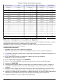
Troubleshooting
Problems with the digestion block cause an alarm to sound and a safety message to show on the
controller display. The controller will no longer apply heat to the digestion block and it will start to
cool. Refer to Table 5.
After the problem is resolved:
• Push CONTINUE to clear the message and let it occur again if necessary.
• Push SUSPEND to disable the message until the system is powered off.
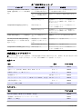
Table 5 Safety messages
Message Possible cause Solution
Overtemp. Protection–
Check Block Temp.
The block is too hot when the sample
is added.
Let the block cool to room temperature
before the next digestion starts.
The voltage switch on the back of the
block is on the wrong voltage setting.
Change the voltage switch to the correct
setting.
An exothermic reaction has occurred. Make sure that the method in the controller
matches the written method. Repeat the
test.
18 English

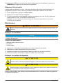
Table 5 Safety messages (continued)
Message Possible cause Solution
Temperature Dropping The sample may have evaporated. Make sure that there is sample in the
digestion tubes.
An endothermic reaction has
occurred.
Make sure that the method in the controller
matches the written method. Repeat the
test.
Check the Dongle The dongle is not connected. Put the dongle in the COM port.
Set Point Exceeds Sample
Boiling Point
The temperature set point is higher
than the sample boiling point.
Change the temperature set point.
The rate of evaporation of the sample
is too high.
Change the temperature set point.
Temperature Unsteady The sample has evaporated. Make sure that there is sample in the
digestion tubes.
Replacement parts and accessories
Note: Product and Article numbers may vary for some selling regions. Contact the appropriate distributor or refer to
the company website for contact information.
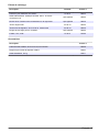
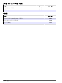
Replacement parts
Description Quantity Item no.
Heat deflector shield 2/package 18091L
Power cord, North America, 230 V, 15 A with C19 connector each 18092L
Test tube and cooling rack, 40-position each 18093L
Cold finger set 40/package 18032L
Digestion tube set, 25 mL and 50 mL, round bottom 40/package 18094L
Replacement dongle for controller each 18095L
Fuse, 15 A, 3 AB 2/package 18105L
Accessories
Description Item no.
Calibrated test tube, 25 mL and 50 mL, round bottom 18090L
Cold finger, for calibrated digestion tubes 18032
Boiling chips, 250 g 18501
English 19
Page is loading ...
Page is loading ...
Page is loading ...
Page is loading ...
Page is loading ...
Page is loading ...
Page is loading ...
Page is loading ...
Page is loading ...
Page is loading ...
Page is loading ...
Page is loading ...
Page is loading ...
Page is loading ...
Page is loading ...
Page is loading ...
Page is loading ...
Page is loading ...
Page is loading ...
Page is loading ...
Page is loading ...
Page is loading ...
Page is loading ...
Page is loading ...
Page is loading ...
Page is loading ...
Page is loading ...
Page is loading ...
Page is loading ...
Page is loading ...
Page is loading ...
Page is loading ...
Page is loading ...
Page is loading ...
Page is loading ...
Page is loading ...
Page is loading ...
Page is loading ...
Page is loading ...
Page is loading ...
Page is loading ...
Page is loading ...
Page is loading ...
Page is loading ...
Page is loading ...
Page is loading ...
Page is loading ...
Page is loading ...
Page is loading ...
Page is loading ...
Page is loading ...
Page is loading ...
Page is loading ...
Page is loading ...
Page is loading ...
Page is loading ...
Page is loading ...
Page is loading ...
Page is loading ...
Page is loading ...
Page is loading ...
Page is loading ...
Page is loading ...
Page is loading ...
Page is loading ...
Page is loading ...
Page is loading ...
Page is loading ...
Page is loading ...
Page is loading ...
Page is loading ...
Page is loading ...
Page is loading ...
Page is loading ...
Page is loading ...
Page is loading ...
Page is loading ...
Page is loading ...
Page is loading ...
Page is loading ...
Page is loading ...
Page is loading ...
Page is loading ...
Page is loading ...
Page is loading ...
Page is loading ...
Page is loading ...
Page is loading ...
Page is loading ...
Page is loading ...
Page is loading ...
Page is loading ...
Page is loading ...
Page is loading ...
Page is loading ...
Page is loading ...
Page is loading ...
Page is loading ...
Page is loading ...
Page is loading ...
Page is loading ...
Page is loading ...
Page is loading ...
Page is loading ...

HACH COMPANY World Headquarters
P.O. Box 389, Loveland, CO 80539-0389 U.S.A.
Tel. (970) 669-3050
(800) 227-4224 (U.S.A. only)
Fax (970) 669-2932
www.hach.com
HACH LANGE GMBH
Willstätterstraße 11
D-40549 Düsseldorf, Germany
Tel. +49 (0) 2 11 52 88-320
Fax +49 (0) 2 11 52 88-210
www.hach-lange.de
HACH LANGE Sàrl
6, route de Compois
1222 Vésenaz
SWITZERLAND
Tel. +41 22 594 6400
Fax +41 22 594 6499
©
Hach Company/Hach Lange GmbH, 2012.
All rights reserved. Printed in U.S.A.
-
 1
1
-
 2
2
-
 3
3
-
 4
4
-
 5
5
-
 6
6
-
 7
7
-
 8
8
-
 9
9
-
 10
10
-
 11
11
-
 12
12
-
 13
13
-
 14
14
-
 15
15
-
 16
16
-
 17
17
-
 18
18
-
 19
19
-
 20
20
-
 21
21
-
 22
22
-
 23
23
-
 24
24
-
 25
25
-
 26
26
-
 27
27
-
 28
28
-
 29
29
-
 30
30
-
 31
31
-
 32
32
-
 33
33
-
 34
34
-
 35
35
-
 36
36
-
 37
37
-
 38
38
-
 39
39
-
 40
40
-
 41
41
-
 42
42
-
 43
43
-
 44
44
-
 45
45
-
 46
46
-
 47
47
-
 48
48
-
 49
49
-
 50
50
-
 51
51
-
 52
52
-
 53
53
-
 54
54
-
 55
55
-
 56
56
-
 57
57
-
 58
58
-
 59
59
-
 60
60
-
 61
61
-
 62
62
-
 63
63
-
 64
64
-
 65
65
-
 66
66
-
 67
67
-
 68
68
-
 69
69
-
 70
70
-
 71
71
-
 72
72
-
 73
73
-
 74
74
-
 75
75
-
 76
76
-
 77
77
-
 78
78
-
 79
79
-
 80
80
-
 81
81
-
 82
82
-
 83
83
-
 84
84
-
 85
85
-
 86
86
-
 87
87
-
 88
88
-
 89
89
-
 90
90
-
 91
91
-
 92
92
-
 93
93
-
 94
94
-
 95
95
-
 96
96
-
 97
97
-
 98
98
-
 99
99
-
 100
100
-
 101
101
-
 102
102
-
 103
103
-
 104
104
-
 105
105
-
 106
106
-
 107
107
-
 108
108
-
 109
109
-
 110
110
-
 111
111
-
 112
112
-
 113
113
-
 114
114
-
 115
115
-
 116
116
-
 117
117
-
 118
118
-
 119
119
-
 120
120
-
 121
121
-
 122
122
-
 123
123
-
 124
124


Ask a question and I''ll find the answer in the document
Finding information in a document is now easier with AI
in other languages
- français: Hach Lachat BD40HT Manuel utilisateur
- español: Hach Lachat BD40HT Manual de usuario
- português: Hach Lachat BD40HT Manual do usuário
- 日本語: Hach Lachat BD40HT ユーザーマニュアル
Related papers


Other documents
-
wtw TresCon Operating instructions
-
Hanna Instruments HI 83214 Owner's manual
-
-
-
-
-
Lovibond 276055 Owner's manual
-
Milwaukee MI451 User manual
-
Omega SC-919 Owner's manual
-