Haier MVAL030MV2AA Owner's manual
- Category
- Split-system air conditioners
- Type
- Owner's manual
This manual is also suitable for

Indoor Unit Operation & Installation Manual
MVAL009MV2AA
MVAL012MV2AA
MVAL018MV2AA
MVAL024MV2AA
MVAL030MV2AA
MVAL036MV2AA
MVAL042MV2AA
MVAL048MV2AA
No. 0150524546
• Please read this manual carefully before using.
• Keep this operation manual for future reference.
Original instructions

Contents
Parts and Functions...........................................................................................................................................................1
Safety ................................................................................................................................................................................2
Maintenance ......................................................................................................................................................................4
Fault Checkup ...................................................................................................................................................................6
Installation Procedures ......................................................................................................................................................7
Electrical Wiring ............................................................................................................................................................... 12
Test Run & Fault Code ....................................................................................................................................................17
Your air conditioner may be subject to any change owing to the improvement of Haier products.
MRV series multiple air conditioning systems adopt the consistent running mode, by which, all indoor units can only be
heating or refrigerating operation at the same time.
To protect the compressor, the air conditioning unit should be powered on for over 12 hours before using it.
All indoor units of the same refrigerating system should use the unied power switch to ensure that all indoor units are in
the state of being powered on at the same time during the operation of air conditioner.
Product Features:
1.Hanging-style installation to save space;
2.Automatic display of faults;
3.Central control function; (optional from our company).
4.If there is a power outage while the system is operating, the system will resume the last mode and settings it was set to
run in.
5.This indoor unit ships with wireless controller. It is compatible with both YR-E17 and YR-E16 wired controllers.
User Manual
Warning
•
I
f the supply cord is damaged, it must be replaced by the manufacturer, its service agent or similarly qualied persons
in order to avoid a hazard.
• T
his equipment should not be used or serviced by personnel who have not been properly trained in its operation and
maintenance.
•
C
hildren should be supervised to ensure that they do not play with the appliance.
•
T
he appliances are not intended to be operated by means of an external timer or separate remote-control system.
•
K
eep the appliance and its cord out of reach of children.
Operation condition:
To use the air conditioner normally, please perform as to the below conditions.
Operating Range of Air Conditioner
Cooling
dry
Indoor
Max. DB: 90°F(32°C) WB: 74°F(23°C)
Min. DB: 64°F(18°C) WB: 57°F(14°C)
Outdoor
Max. DB: 115°F(46°C) WB: 79°F(26°C)
Min. DB: 23°F(-5°C)
Heating
Indoor
Max. DB: 80°F(27°C)
Min. DB: 59°F(15°C)
Outdoor
Max. DB: 75°F(24°C) WB: 59°F(15°C)
Min. DB: -4°F(-20°C)

1
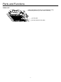
Parts and Functions
Indoor unit
Outlet guide plate (air direction can be adjusted by using
direction adjustment key on the remote controller)
Air-inlet grille
Air lter (inside air-inlet grille)

2
Safety
• This manual should be saved and stored close to this air conditioning equipment.
• There are two types if indications. Both are related to safety and should be strictly followed. "
Warning" highlights
issues that pose a risk of major injury or death. "
Caution" highlights issues that pose a risk of equipment or bodily
injury.
• After installation and start-up commissioning, please give the manual to the user. The manual should be kept in safe
place and close to the unit.
• Installation and maintenance should be performed by an authorized agency. The wrong operation of this air condition
equipment may cause water damage, electric shock or re.
• Please install the unit on the top of a solid foundation or structure which is strong enough to support the unit.
• The installation of this condition equipment should follow local building codes.
• Use the right cable size, secure the terminal rmly, organize the cables well and make sure no tension is added on
cables. Cable insulation should not be damaged. Improper wire installation may lead to re.
• This unit is only compatible with R-410A refrigerant. If any other gas enters the system, it may lead to abnormal high
pressure which may cause damage or injury.
• Only use branches supplied by Haier. Use of any other branches will void warranty.
• Keep the condensate drain pipe away from toxic gas vents to prevent possible pollution of indoor environment.
• Care should be taken to ensure that there are no refrigerant leaks. R-410A is a heavy gas and will displace oxygen.
Ventilate the area if a leak if found.
• The unit is not explosion-proof. Please keep it away from ammable gases.
• The drain pipe should be installed per this manual to ensure proper drainage. The pipe should be well insulated to avoid
condensation. Wrong installation may lead to water damage.
• Both liquid pipe and the vapor pipe should be also well insulated. Not enough insulation may lead to system
performance deterioration or condensate formation.
• This equipment should not be used or serviced by personnel who have not been properly trained in its operation and
maintenance.
• Children should be supervised to ensure that they do not play on or near the equipment.
• Keep the appliance and its cord out of reach of children.
• The appliances are not intended to be operated by means of an external timer or separate remote-control system.
WARNING
• Grounding wire should be connected to the grounding bar. The grounding wire cannot be connected to the gas pipe,
water pipe, lightening rod or the telephone grounding wire. Improper grounding may cause electric shock.
• A circuit breaker should be installed. If not, it may cause electric shocks or accidents.
• After installation, the air condition equipment should be powered on and passed the electric leakage current lest.
• If the ambient humidity is more than 80%, if the water discharge hole is blocked or the lter becomes dirty or the airow
speed changes, this may lead to condensate water leaks. There may also be some drops of water spraying out.
CAUTION

3
Safety
Attention
• Do not put any heating apparatus under the
indoor units. The heat may cause distortion of the
units.
• Pay attention to the ventilation to avoid anoxic injury.
• Do not place an open ame in the path of blowing air.
• Do not install in a corrosive environment. If the base
collapses, the unit may fall and cause damage,
product failure, personal injury or death.
• Do not use the unit for special purposes such
as preserving foods, works of art etc. It is an air
conditioner for comfort cooling / heating, not a
precision refrigeration system.
• Use the correctly rated breaker or fuse. Improper
breaker or fuse may lead to re, electric shock,
explosion, personal injury or death.
• Turn off the power to save energy if the unit will
be not used for a long period. If the unit is not
powered off, it will consume power.
• Do not permit water or steam to enter the unit and
the wired controller. There is risk of unit failure, re,
electric shock, personal injury or death.
• 3-minutes protection
To protect the unit, there is a 3-minute time-out after
the unit stops or after power is applied.
• Close the window to avoid outdoor air getting in.
Curtains or window shutters can be put down to avoid
the sunshine.
• Do not touch the power switch with the wet hand to
avoid power shock.
• Turn off the system and remove power when servicing
the unit.
• Don't remove power while system is running.
• Do not clean the unit with water spray. There is risk
of unit failure, re, electric shock, personal injury or
death.
• Keep ammable gas or combustibles away from the
unit. There is risk of product failure, re, personal
injury or death.
• Please keep children away from this air condition
equipment.
Notices during Operation

4
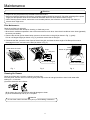
Maintenance
Attention
• Repair can only be performed by licensed service technicians.
• Before touching the electrical connections, all power supplies should be turned off. Only after switching off the power
supply can the operator clean the air conditioner otherwise there is a risk of electric shock or injury.
• When cleaning the air cleaner, make sure to use a stable platform; don't ush the air conditioner with water, or
electric shock might occur.
Filter Maintenance:
Clean the air lter & air inlet grid.
• Don't remove the air lter except for cleaning, or faults may occur.
• When the air conditioner operates in the environment with too much dust, clean the air conditioner more times (generally
once every two weeks).
1. Remove the air inlet grid as shown below: press on the two locks on the grid (as shown in Fig. 1), gently
lift it at a 45 degree angle (as shown in Fig. 2), and then remove the air inlet grid.
2. Dismantle the lter: press the outer frame of the air inlet grid, and draw the base angle of the lter pull it out as to
disengage the locks, and remove the lter (as shown in Fig. 3).
Clean the air lter with a vacuum or water to remove dust.
For heavy dust, use the vacuum or directly spray mild soap on the air inlet grid, and then clean it with water after
soaking for ~10 minutes.
(A) remove dust with dust collector.
(B) for heavy dust, use a soft brush and mild detergent to clean.
(C) rinse off water/soap and dry in a cool place.
Fig. 1 Fig. 2 Fig. 3
Cleaning Air Cleaner
• Do not clean it with hot water 122°F(50°C) to avoid fading or distortion.
Attention
press down the locks
hinge
lock port
remove air inlet grid
locks
bottom of gauze
hinges
frame of air inlet grid

5
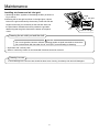
Maintenance
Installing air cleaner and air inlet grid:
1. Mounting the lter: opposite of dismantling the lter (as shown in
Fig. 3 above).
2.Mounting the air inlet grid: as shown in the right gure, clip the
locks on the grid as directed by the arrows, put the side with the
hinges into the lock port, and then put the side with locks into
the panel frame. Release the locks to position the grid after
determining that the grid is ush with the bottom of the panel
frame.
Cleaning the air outlet port and the shell:
• Do not use gasoline, benzene, diluents, polishing powder or liquid insecticide to clean them.
• Do not clean them with hot water of over 122°F(50°C) to avoid fading or distorting.
Attention
• Wipe them with a soft dry cloth.
• Water or neutral dry cleaner is recommended if the dust cannot be removed.
Cleaning Louvers:
• To avoid damage to the louvers care should be taken when cleaning. Use damp cloth and mild detergent.
hinge
lock port
locks
insert air inlet grid

6
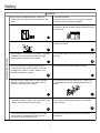
Fault Checkup
Please check the following when consigning repair service:
All these are not problems
Symptoms Reasons
Water ow sound
Water ow sound can be heard during starting operation, during operation
or immediately after stopping operation. When it starts for 2-3 minutes, the
sound may become louder, which is the owing sound of refrigerant or the
draining sound of condensate water.
Cracking sound
During operation, the air conditioner may make a crackling sound, which
is caused from the temperature changes of the heat exchanger.
Terrible smell in outlet air
The terrible smell may be caused from walls, carpet, furniture, clothing,
cigarette and cosmetics, that attach to the air conditioner.
Flashing operating indicator
When switching it on again after power failure, turning on the manual
power switch will show the operating indicator ashes.
Awaiting indication
It displays the waiting indication as it fails to perform refrigerating operation
while other indoor units are in heating operation. When the operator set it to
the cooing or heating mode and the operation is opposite to the setting, it
displays the waiting indication.
Idle indoor unit still has sound of
refrigerant owing and radiating
temperatures.
To prevent oil and refrigerant from blocking the valve of idle units (off or
satised) while other indoor units are operating, some refrigerant ow is
allowed to pass through. This may result in some radiating temperature and
ow noise.
Clicking sound when unit comes on.
When the conditioner is powered on, the sound is made due to the
expansion valve resetting.
Please make another check.
Start or stop working automatically Check if it is set to Timer-ON and Timer-OFF.
Failure to work
Check if there is a power failure.
Check if the supply fuse and breaker are disconnected.
Check if the unit is displaying any faults.
Check if wait symbol is displayed. This is due to other indoor units connected
to the same outdoor unit are running in the opposite mode. System cannot
heat and cool simultaneously.
Bad cooling & heating effects
Check if air intake port and air outlet port of outdoor units are blocked.
Check if the door and windows are open.
Check if the air lter is blocked with sludge or dust.
Check if the setting of fan speed is set to low speed.
Check if the setting in in Fan Operation state.
Check if the temperature setting is correct.
Under the following circumstances, immediately stop the operation, disconnect the manual supply switch and contact the
after-service personnel.
• When buttons are inexible actuated;
• When fuse and breaker have been burnt over and over;
• When there are foreign objects or ice in the unit.;
• When system won't run after resetting power and waiting for 3-minute time out;
• When other abnormal conditions occur.

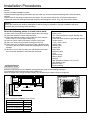
7
Installation Procedures
Caution:
Choose a suitable installation location.
Avoid places with high salinity (salt water) and high sulfur gas. Unit will corrode and damage will not be covered by
warranty.
Avoid excess oil (including mechanical oil) and steam. This can reduce efciencies and product performance.
Avoid areas where machines generate high frequency electromagnetic waves. They can cause control issues.
Warning:
protect the machine from winds or earthquake, install according to regulations. Improper installation will cause
accidents due to unit coming loose and falling.
(1) where there is enough room for the machine above the ceiling;
(2) where the drainpipes can be well positioned;
(3) where the distance between the air outlet port of the machine
and the oor is not more than 8.86ft(2.7m);
(4) where air inlet & outlet of the indoor units are not blocked;
(5) where it is sturdy enough to bear the weight of the unit;
(6) where there are no televisions, pianos or other valuables under
the indoor units as to avoid condensate dropping down, causing
damage.
(7) Where it is over 3.28ft(1m) away from the television and radio
as to avoid the interference from television and radio.
Select the following places to install indoor units.
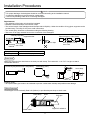
Ensure the required space for installation and maintenance (refer to the following drawings).
The installation height should be kept within 8.86ft(2.7m).
When the height of the ceiling exceeds 8.86ft(2.7m), the warm air is harder to blow to the ground.
Installation Space
Required Tools for Installation
• Brazing torch
• 15% silver phosphorous copper brazing alloy
• Wire stripper
• Soap-and-water solution or gas leakage detector
• Torque wrench
• 17mm, 22mm, 26mm
• Tubing cutter
• Reaming tool
• Flaring tool
• Razor knife
• Measuring tape
• Level
• Vacuum pump
• Micron gauge
• Nitrogen
• Mini-Split AD-87 Adapter (1/4” to 5/16”)
• Non-adhesive Tape
• Adhesive Tape
• Electrical wiring
≥60in
(1500mm)
Outlet
Outlet
Suction inlet
≥40in (1000mm)
Over 98in (2500mm)
above the ground
H
≥60in
(1500mm)
≥60in (1500mm)
≥60in (1500mm)
≥60in (1500mm)
≥60in (1500mm)
Space required for installation, unit: in (mm)
Model H
MVAL009~018MV2AA 8.2 (206)
MVAL024MV2AA 9 (227)
MVAL030~036MV2AA 10.6 (269)
MVAL042~048MV2AA 12.3 (311)

8
Installation Procedures
Note:
Before suspending the indoor unit, select an installation location according to the piping and wiring in the ceiling, and
determine the direction of the piping. Prepare all pipes (refrigeration and drainage) and wiring (power supply,
communication and control) to be ready to connect once unit is installed.
1. Use cardboard template to locate desired location. Mark the mounting positions of the threaded rods using the guides
on the cardboard template.
2. Install 3/8in threaded rods to structure using appropriate fasteners.
3. Add nuts and washers at approximate height.
4. Lift the cassette and position the threaded rods into the 4 mounting clips on each corner of the cassette unit.
5. Adjust the height of the unit so that bottom surface is recessed 1 inch from ceiling surface.
6. Using a level, adjust the nuts on the threaded rods to obtain a level reading across the bottom of the cassette unit.
7. Tighten the top nuts to lock unit into place. An additional nut on top and bottom of bracket may be added to jam against
the installation nuts to prevent them from loosening due to unit vibration.
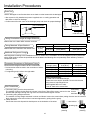
Hanging Unit
Tighten the nut on the washer.
nut (provided on site)
washer
hoisting foot
washer
tightening (dual nuts)
[secure hoisting foot] [secure washer foot]
• Check if the indoor unit is level with the water level and
that the polythene tube drains with water. Check if the
size of the ceiling hole is correct. Remove any water
before mounting the decorated board.
• Fasten the screws to make the height difference between
the two sides of the indoor unit less than 0.2in(5mm).
Model H
MVAL009~018MV2AA 236
MVAL024MV2AA 257
MVAL030~036MV2AA 299
MVAL042~048MV2AA 341
gap between studs 31in (765mm)
gap between studs 31in (765mm)
ceiling 36in (890mm)
decorated board 38in (950mm)
indoor unit 34in (850mm)
indoor unit 34in (850mm)
ceiling 36in (890mm)
decorated board 38in (950mm)
130
H
Hanger bracket
Ceiling
Trim panel
Distance between indoor unit and
ceiling≤0.8in (20mm)
Distance between indoor unit
and ceiling≤0.8in (20mm)
Overlap between ceiling and
trim panel≥1.2in (30mm)
Overlap between ceiling and
trim panel≥1.2in (30mm)

9
Requirements:
• The drainpipe of the indoor unit should be insulated.
• Maintain a downward slope. Avoid waves or dips.
• The horizon length of the drainpipe should be kept with 65.6ft(20m). Under the condition of long pipes, supports can be
provided every 4.9-6.6ft(1.5~2m) as to avoid unevenness.
• The central piping should be connected according the following drawing.
• Take care not to apply external force on the connection of the drainpipes.
4.9-6.6ft(1.5m~2m)
support bracket
heat
insulating
material
down gradient
over 1/100
No waves or dips
Pipe should drop 3.9in (10cm)
down gradient
over 1/100
VP30
Installation Procedures
• For proper drainage, the drainpipes should be connected according to the installation manual.
• Insulate the drainpipes to prevent exterior condensation.
• Follow local plumbing codes when connecting drainpipes.
Attention
Piping Material 1-1/4 inch sch. 40 PVC
Insulating Material 1/4 inch thick Polyethylene wrap.
45°bending (max.)
45°
Drain Hose
Attach the soft end of the drain hose to the drain port with clamp. The hard end is 1-1/4 PVC. Use glue to attach
condensate drain line.
eccentricity adjustment max.0.78in(20mm)
20
Insulation Wrap:
• All exposed drain pipe needs to be insulated to prevent condensation buildup and possible water damage.
Lifting Drainpipe
The drainpipe can be maximally lifted 24in (360mm) to provide adequate slope to drain water.
indoor unit
hose
hose
hose clamp
hose clamp
Hose
Hose clamp
PVC pipe
Rigid PVC adhesive
Water outlet

10
Drain Test
Test the drainpipe to conrm that there are no leaks or other issues with the drainpipe.
3.9in(100
mm) below
lifting 14in
(360mm) below
lifting 23.6in
( 600mm )below
under the ceiling
• After system is fully installed and power is applied, turn on cooling operation and
add water to check for drainage.
• Conrm sound from the motor of the drainage pump and check for proper drainage.
joint of drainpipe
Installation Procedures
Tubing Permissible Length & Height Difference
Please refer to the Haier MRV selection software.
Additional Refrigerant Charge
Add refrigerant according to the installation manual of outdoor unit. The addition of R410A refrigerant must be performed
with a digital scale to ensure the specied amount is added. Not following this can potentially cause efciency issues or
compressor failure.
Tubing Materials & Specications
Please refer to the manual of the outdoor unit.
Model MVAB009~018MV2AA MVAL024~048MV2AA
Tubing Size
in (mm)
Gas pipe Ø1/2"(Ø12.7) Ø5/8"(Ø15.88)
Liquid pipe Ø1/4"(Ø6.35) Ø3/8"(Ø9.52)
Tubing
Material
R-410a rated copper tubing
Connecting Procedures of Refrigerant Tubing
Connect all the refrigerant tubes via are connections.
• Dual wrenches must be used in the connection of indoor
unit tubing.
• For tightening torque refer to the right table.
Outer Diameter of
Tubing in (mm)
Mounting Torque
lb-in (N-m)
Flare Torque Spec
ft-lb (N-m)
Ø1/4"(Ø6.35) 104.4 (11.8) 13 (18)
Ø3/8"(Ø9.52) 216.8 (24.5) 30 (40)
Ø1/2"(Ø12.7) 443.7 (49.0) 43 (59)
Ø5/8"(Ø15.88) 693.9 (78.4) 76 (103)
wrench
Cutting and Enlarging
• Cut the tube to the needed length.
• Ream the cut to remove shoulder. Do this with the tube
facing down to help llings fall out.
• Add supplied are nut to tube.
• Use 45° are tool to create are.
1. Connecting using circular crimp terminals:
The method of using circular terminal is shown in the gure. Take off the screw, connect it to the
terminal after placing it through the ring at the end of the lead and tighten it down.
2. Connecting using straight terminals:
The method of using straight terminals is shown as follows: loosen the screw before putting the wire into the terminal
block, tighten the screw and conrm it has been tightened by pulling the line gently.
3. Clamp the wires:
Secure the wires with clips which should press on the insulation of the wires.
Wire Connections
Connecting
circular
terminals:
correct
pressing
wrong
pressing
terminal tier
pressing clip
Model MVAL009~018MV2AA MVAL024~048MV2AA
Tubing Size (in)
Gas pipe Ø1/2" Ø5/8"
Liquid pipe Ø1/4" Ø3/8"
Tubing Material Phosphor deoxybronze seamless pipe (TP2) for air conditioner

11
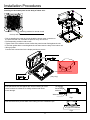
Installing the decorated panel on the body of indoor unit:
receiving window for remote control
the lamp will not ash when wired controller is used
• Prior to attaching the panel to the unit locate the louver motor connector on
the panel and the unit. Orientate the panel so they can connect.
• First temporarily position it with screws.
• Tighten each screw a little at a time to allow the panel to seat ush against the unit.
• If the foam gasket does not seal against the unit then lower the body of the indoor unit.
• Wiring of panel:
Connect both connections for the display and louver motors.
Attention
If the panel does not seal against the unit then leaking air could
cause moisture to condense on ceiling surfaces and cause
water damage.
Unit must be level to prevent water from leaking from the condensate pan.
Fig.1
any gap is not allowed
Fig.2
air leakage
Water damage
Condensing
moisture
side of decorated board
side of indoor unit
Inaccurate board location
(may vary)
Installation Procedures

12
Electrical Wiring
WARNING
Attention
• Follow local codes when selecting wire gauge and connecting to house power.
• Use the cable strain relief clips and locking conduit clamps to prevent wires from being pulled off terminal posts.
• Unit must be properly grounded. Do not use water or gas piping, phone ground or lightning rod.
• Only copper wire can be used. A properly sized breaker should be provided, or electric shock may occur.
• Unit requires 208/230VAC - 2 voltage wires and a ground. No neutral.
• All indoor units should be wired to the same breaker to prevent some of the units from being powered off while others
are energized.
• Controller wiring and refrigerant tubing can be arranged and ran together.
• Disconnect power from both outdoor and indoor units prior to servicing any component in the system.
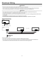
Supply Wiring Drawing
• Indoor units and outdoor units should be connected to separate power breakers
• Indoor units must share one single electrical breaker. Circuit breaker specications should be calculated. It is
recommended to have both indoor & outdoor units connected to GFCI and surge devices.
power source: 208/230V~, 60Hz
outdoor
L1(L) L2(N)
power source: 208/230V~, 60Hz
Indoor 1
Indoor 2 Indoor 9
L1(L) L2(N)
L1(L) L2(N)
L1(L) L2(N)
......

13
Electrical Wiring
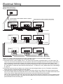
Signal Wiring Drawing
Oudoor unit, central control and all indoor units are of parallel connection via two lines without polarity.
There are three ways of connecting the line control and indoor units:
A. One wired control to control multiple units, i.e. 2-3 indoor units, as shown in the above gure, (1-3 indoor units). The
indoor unit 3 is the wire controlled main unit and others are the wired controlled sub units. The remote control and the
main unit (directly connected to the indoor unit of wired control) are connected via three wires with polarity. Other
indoor units and the main unit are connected via three lines with polarity. SW01 on the main unit of wired control is set
to 0 while SW01 on other sub units of wired control are set to 1, 2 and so on in turn. (Please refer to the code setting A
at page 15)
B. One wired control controls one indoor unit, as shown in the above gure (indoor unit 4-8). The indoor units and the
wired control are connected via three lines with polarity.
C. Two wired controls control one indoor unit, as shown in the gure (indoor unit 9). Either of the wired controls can be
set to be the master wired control while the other is set to be the auxiliary wired control. The master wired control and
indoor units, and the master and auxiliary line controls are connected via three lines with polarity.
Note: For DC motor/low ESP duct type, the PCB comes with the terminal blocks. Please be sure to pay attention to do
the wiring according to the labels. The power lines and signal lines go through the metal wire hole separately with the
protective sleeve of the connecting line.
P Q
P QA B C P Q A B C P Q A B C
A B C
Outdoor
Indoor 1
(950 CASSETTE)
Indoor 4
Indoor 7
Indoor 2
Indoor 5
Indoor 8
Indoor 3
Indoor 6
Indoor 9
P Q A B C P Q A B C P Q A B C
P Q A B C P Q A B C P Q A B C
A B C A B C
A B C
A B CA B C
A B CA B C
Control wire for wired controller with polarity
Wired controller
Wired controller
Wired controller
Wired controller
Wired controller
Wired controller Wired controller
Wired controller
Communication wire between indoor & outdoor
without polarity

14
Electrical Wiring
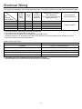
Wire gauge size and breaker size for total indoor amp draw. Current NEC guidelines and local codes will trump this chart.
Items
Total
Current of
Indoor Units(A)
Cross
Section
AWG
(mm
2
)
Length
in.(m)
Rated
Current of
Overow
Breaker(A)
Rated current of residual
Circuit Breaker(A)
Ground Fault Interrupter(mA)
Response time(S)
Cross Sectional
Area of Signal Line
<7 14(2.5) 65.6(20) 10 10 A,30 mA,0.1S or below
16 AWG (1.25mm
2
)
≥7 and <11 12(4) 65.6(20) 15 15 A,30 mA,0.1S or below
≥11and <16 10(6) 82(25) 20 20 A,30 mA,0.1S or below
≥16 and <22 8(8) 98.4(30) 30 30 A,30 mA,0.1S or below
≥22 and <27 6(10) 131(40) 30 30 A,30 mA,0.1S or below
• The shielding lay of the controller wire must be grounded at one end.
• The total length of the controller wire shall not be more than 1968ft(600m).
Wired Controller ABC Chart
Length of Controller Wire ft (m) Wiring Dimensions AWG (mm
2
)
<328(100) 22(0.3) x 3 core shielding line
≥328(100) and <656(200) 20(0.5) x 3 core shielding line
≥656(200)and <984(300) 18(0.75) x 3 core shielding line
≥984(300) and <1312(400) 16(1.25) x 3 core shielding line
≥1312(400) and <1968(600) 14(2) x 3 core shielding line
• The electrical power line and signal lines must be tightened.
• Every indoor unit must have a ground connection.
• The power wire should be size up if it exceeds the permissible length.
• Shielding of the wire of all the indoor and outdoor units should be connected together and grounded at one point.
• Signal lines should not exceed 3280ft(1000m).

15
Electrical Wiring
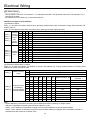
• The dip switch is set to the "On" position if “1” is indicated in the table. The dip switch is set to the "Off" position if "0" is
indicated in the table.
• Dip switches set in the factory to on are marked with red.
Denition principles of code switches:
(A) Denition of SW01:
SW01_1-4 is used to set indoor address when grouping multiple indoor units connected to single wired controller YR-
E16B or YR-E17.
SW01_5-8 set capacity of the indoor unit (factory set). Must only set when replacing board.
Dip Switch Setting
SW01_1
SW01_2
SW01_3
SW01_4
Address
of wire
controlled
indoor
unit
(group
address)
[1] [2] [3] [4] Address of wire controlled indoor unit (group address)
0 0 0 0 0# (wire controlled master unit) (default)
0 0 0 1 1# (wire controlled slave unit)
0 0 1 1 2# (wire controlled slave unit)
0 0 1 1 3# (wire controlled slave unit)
… … … … ……
1 1 1 1 15# (wire controlled slave unit)
SW01_5
SW01_6
SW01_7
SW01_8
Capability
of indoor
unit
[5] [6] [7] [8] Capability of indoor unit
0 0 1 0 9000BTU
0 0 1 1 12000BTU
0 1 1 0 18000BTU
0 1 1 1 24000BTU
1 0 0 1 30000BTU
1 0 1 0 36000BTU
1 0 1 1 42000BTU
1 1 0 0 48000BTU
(B) Denition and description of SW03
SW03_1-8 is used to set indoor unit address on system. Set address only if using central controller YCZ-A004. Leave
default if no central controller is used.
Note:
• Set the address by code when connecting the centralized controller or gateway or charge system.
Address of centralized controller=communication address+0 or+64.
SW03_ 2=OFF, address of centralized controller=communication address+0=communication address
SW03_ 2=ON, address of centralized controller=communication address+64 (applies when centralized controller is
used and there are more than 64 indoor units)
SW03_1
Address setting
mode
[1] Address setting mode
0 Automatic setting (default)
1 Code-set address
SW03_2
~
SW03_8
Code-set indoor
unit address
and centralized
controller address
[2] [3] [4] [5] [6] [7] [8] Address of indoor unit
Address of centralized
controller
0 0 0 0 0 0 0 0# (Default) 0# (Default)
0 0 0 0 0 0 1 1# 1#
0 0 0 0 0 1 0 2# 2#
… … … … … … … … …
0 1 1 1 1 1 1 63# 63#
1 0 0 0 0 0 0 0# 64#
1 0 0 0 0 0 1 1# 65#
1 0 0 0 0 1 0 2# 66#
… … … … … … … … …
1 1 1 1 1 1 1 63# 127#

16
Electrical Wiring
Function switches
For other wired remote controller settings, please refer to controller manual.
The difference between master and slave wired controller
Comparison
item
Master wired
controller
Slave wired controller
Function All function
1.ON/OFF, Mode, Fan speed, Temp, Setting, Swing, Energy saving, Clock function, Mode
Setting, Screen Saving and Child lock are available.
2.Cancel the lter cleaning icon.
3.Look up the detailed parameter and malfunction code.
DIP switch On/Off station Function Default setting
Sw1
On Slave wired controller
Off
Off Master wired controller
Sw2
On Ambient temp. display on
Off
Off Ambient temp. display off
Sw3
On Collect ambient temp. from PCB of indoor
Off
Off Collect ambient Temp. from wired controller
Sw4
On Non-volatile memory invalid
Off
Off Non-volatile memory valid
Sw5
On Old protocol
Off
Off Self adaption
Sw6
On reserved
Off
Off reserved
Sw7
On Model with Up/Down and Left/Right swing
Off
Off Model with Up/Down swing
Sw8
On Fresh Air unit
Off
Off General unit
Dip Switch Setting of YR-E17 Wired Controller

17
• Connect it to the power supply of the outdoor units to energize the heater of the compressor. To protect the compressor
at startup, power it on 12 hours prior to the operation.
Checkup of Installation
check if the main voltage is correct
check for any leaks at the piping joints
check if the connection of the main power for the indoor & outdoor units are correct
check if the serial numbers of the terminals are matched properly
check if the installation place meets the requirement
check if there is too much noise
check if the connecting line is fastened
Check if the refrigerant and condensation lines are insulated
check if the water is drained to the outside
check if the indoor units are positioned
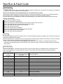
Test Run & Fault Code
Before Test Run
Do ask the installation personnel to make a test run. Take the testing procedures according to the manual and check if the
temperature regulator works properly.
When the machine fails to start due to the room temperature, the following procedures can be taken to do the compulsive
running. The function is not provided for the type with remote control.
• Set the YR-E17 wired controller to cooling/heating mode, press "ON/OFF" button for 10 seconds to enter into the
compulsive cooling/heating mode. Press "ON/OFF" button again to quit the compulsive running and stop the operation
of the system.
Test Run
When any fault appears, consult the fault code of line control or the number of LED ashes on the control panel of the
indoor units/health lamp of receiving window of remote control. Refer to the below table lookup fault descriptions.
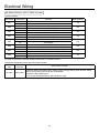
Indoor Unit Faults
Failure code at wired
controller
PCB LED5(Indoor Units)/
Receiver Timer Lamp(Remote
Controller)
Fault Descriptions
01 1
Fault of indoor unit ambient temp. sensor TA
02 2
Fault of indoor unit pipe temp. sensor TC1
03 3
Fault of indoor unit pipe temp. sensor TC2
04 4
Fault of indoor unit dual heat source temp. sensor
05 5
Fault of indoor unit EEPROM
06 6
Fault of communication between indoor & outdoor units
07 7
Fault of communication between indoor unit and wired control
08 8
Fault of indoor unit water drainage
09 9
Fault of duplicate indoor unit address
0A 10
Reserve
0C 12 Fault of zero crossing
0E 14 Fault of DC fan
Outdoor Unit Code 20
Corresponding faults of outdoor units
Fault Remedies
Check if the connections of the drainpipe and wire connection lines are correct.
The drainpipe shall be placed at the lower part while the connection line placed at the upper part. Insulating measures
should be taken such as winding the drainpipe especially on the indoor units with insulating materials.
The drain pipe should be installed as a slope to avoid protruding from the upper part and concaving at the lower part.

Qingdao Haier Air Conditioner Electric Co.,Ltd.
Haier Industrial Park,Qianwangang Road,Eco-Tech Development Zone,Qingdao 266555,
Shandong,P.R.C.
-
 1
1
-
 2
2
-
 3
3
-
 4
4
-
 5
5
-
 6
6
-
 7
7
-
 8
8
-
 9
9
-
 10
10
-
 11
11
-
 12
12
-
 13
13
-
 14
14
-
 15
15
-
 16
16
-
 17
17
-
 18
18
-
 19
19
-
 20
20


Haier MVAL030MV2AA Owner's manual
- Category
- Split-system air conditioners
- Type
- Owner's manual
- This manual is also suitable for
Ask a question and I''ll find the answer in the document
Finding information in a document is now easier with AI
Related papers
-
Haier MVAB009MV2AA Owner's manual
-
Haier MVAB009MV2AA User manual
-
Haier MVAD024MV2AA User manual
-
-
-
-
-
-
-
Other documents
-
Mitsubishi Electric PCA-A.KA5 Installation guide
-
SystemAir SWC-86ED User manual
-
GREE GKH60K3HI Owner's manual
-
Cooper&Hunter CH12LCDTUICHHYP12SPH230VO Installation guide
-
 PYLE Audio PQA4100 User manual
-
Carrier 40MBQB09F--3 Installation guide
-
 HEIL DLFBHC02K1A Installation Instructions Manual
-
SystemAir SYSPLIT DUCT 24 LNS HP Q Owner's manual
-
Panasonic CZ-RWST1U Installation guide
-
Reznor BD4W**SAK Installation guide

