
Fröling Heizkessel- und Behälterbau Ges.m.b.H, Industriestraße 12, A-4710 Grieskirchen
Tel +43 (0) 7248 606-0 Fax +43 (0) 7248 606-600 [email protected] www.froeling.com
Op e r a t i n g I ns t r u c t i o ns
P2 Pellet Boiler
with Lambdatronic P 3100 (from version 24.17)
Read and follow the operating instructions and safety information.
Subject to technical change.

Introduction
Page 2
B0190806
I
I
Dear Customer,
Congratulations on choosing a quality product from FRÖLING.
The FRÖLING P2 Pellet Boiler is a state-of-the-art design that conforms
to all currently applicable standards and testing guidelines.
Please read and observe the operating instructions and always keep
them available in close proximity to the boiler. They contain safety
information and all the operation and maintenance specifications needed
to operate the boiler safely, properly, and economically.
The instructions have been prepared to the best of our knowledge.
However if you find any errors please let us know.
Subject to technical change.

Contents
Fröling Heizkessel- und Behälterbau Ges.m.b.H, Industriestraße 12, A-4710 Grieskirchen, Austria Page 3
Tel +43 (0) 7248 606-0 Fax +43 (0) 7248 606-600 info@froeling.com www.froeling.com
B0190806
C
1 Product Overview 6
2 Safety 8
2.1
Safety Information 8
2.2
Permitted uses 9
2.2.1
Permitted fuel ................................................................................................... 9
2.2.2
Who can operate the boiler ................................................................................. 9
2.3
Design Information 10
2.3.1
Official approval and obligation to report ............................................................ 10
2.3.2
Requirements for heating water......................................................................... 10
2.3.3
Ventilating the Boiler Room............................................................................... 10
2.3.4
Heating System Installation/ Standards.............................................................. 11
Return feed lift ............................................................................................... 11
2.3.5
Chimney connection / chimney system ............................................................... 12
Draught limiter ............................................................................................... 12
Boiler data for constructing the flue gas system .................................................. 12
2.4
Safety Devices 13
2.4.1
Devices for preventing the boiler from overheating .............................................. 14
Thermal discharge safety device ....................................................................... 14
Safety Temperature Limiter STL........................................................................ 14
Safety valve ................................................................................................... 14
2.5
Safety information for installation room 14
2.6
Other risks 15
2.7
Emergency procedure 16
2.7.1
System overheating ......................................................................................... 16
2.7.2
Smell of flue gas.............................................................................................. 16
2.7.3
Fire ................................................................................................................ 16
3 Operating the System 17
3.1
Initial startup 17
3.2
Filling/ refilling the store with fuel 17
3.3
Heating up the boiler 18
3.3.1
Switching on the system................................................................................... 18
3.3.2
Switching on the boiler ..................................................................................... 18
3.3.3
Controlling the boiler........................................................................................ 18
3.3.4
Switching off the boiler..................................................................................... 18
3.3.5
Switching off the System .................................................................................. 18
3.4
Emergency (Firewood) Operation 19
3.4.1
Modifying the boiler for emergency operation using firewood................................. 19
3.4.2
Filling the combustion chamber with firewood ..................................................... 20
3.4.3
Setting the controls.......................................................................................... 20
3.5
Modifying the boiler for normal operation 21

Contents
Page 4
B0190806
I
C
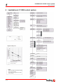
4 Lambdatronic P 3100 control system 22
4.1
Heating times table 23
4.2
Display values 24
4.2.1
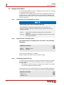
Modes .............................................................................................................25
4.2.2
Operating statuses............................................................................................26
4.3
Changing parameters and values 27
4.4
Menus 27
4.4.1
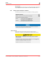
Settings menu..................................................................................................28
Setting boiler temperature ................................................................................28
Set storage tank temperatures ..........................................................................28
Set DHW tank temperatures..............................................................................28
Setting heating times .......................................................................................29
Allocating heating times to heating circuits..........................................................29
Setting the runtime of the ash screw ..................................................................30
Setting the pellet filling time .............................................................................30
Setting boiler times..........................................................................................30
4.4.2
Manual operation menu .....................................................................................30
5 Boiler maintenance 31
5.1
Inspection, cleaning, and maintenance 32
5.1.1
Inspection .......................................................................................................32
Checking the combustion chamber and pellet burner............................................32
Checking the level of the ash.............................................................................32
Emptying the ash drawer (P2 ash drawer module) ...............................................33
Emptying the ashcan (P2 ash screw module).......................................................33
Cleaning the pellet burner.................................................................................34
Checking the thermal discharge safety device......................................................34
Checking the system pressure ...........................................................................35
5.1.2
Annual Check ...................................................................................................35
Checking the heat-exchanger and flue gas collection chamber ...............................35
Clean the flue gas sensors ................................................................................36
Checking the primary air pipes ..........................................................................36
Checking the gearing........................................................................................36
Cleaning the induced draught ventilator..............................................................36
Clean the smoke flue pipe.................................................................................37
Checking the draught controller flap and explosion flap ........................................37
Checking the combustion chamber door..............................................................37
Clean the bypass line (only for systems with suction unit).....................................37
5.2
Maintenance Agreement / Customer services 38
5.3
Replacement parts 38
6 Troubleshooting 39
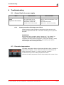
6.1
General faults in power supply 39
6.1.1
System procedure following power failure............................................................39
6.2
Excessive temperature 39
6.3
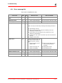
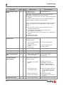
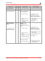
Faults with a fault message 40
6.3.1
Procedure for fault messages .............................................................................40
6.4
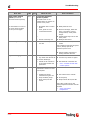
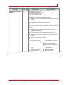
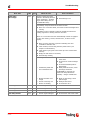
Error message list 41

Contents
Fröling Heizkessel- und Behälterbau Ges.m.b.H, Industriestraße 12, A-4710 Grieskirchen, Austria Page 5
Tel +43 (0) 7248 606-0 Fax +43 (0) 7248 606-600 info@froeling.com www.froeling.com
B0190806
C
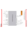
7 Installers and service technicians 48
7.1
Connection layout of the boards 48
7.2
Connection instructions 50
7.2.1
Mains connection ............................................................................................. 50
7.2.2
Heating circuit pumps for floor or wall heating..................................................... 50
7.2.3
Jumper setting for solar control ......................................................................... 51
7.2.4
Flue gas sensor ............................................................................................... 51
7.2.5
Remote control................................................................................................ 51
7.2.6
RBG 3100 room console ................................................................................... 52
7.2.7
PC Visualisation ............................................................................................... 52
7.2.8
Heating circuit pump 0 / Oil - oil burner contact .................................................. 53
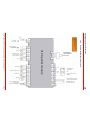
7.3
Connection layout of the pellet module 54
7.3.1
Pellet module with ash discharge ....................................................................... 54
7.3.2
Pellet module with suction system ..................................................................... 55
7.3.3
Overview of connected components ................................................................... 56
7.3.4
Connection instructions for Komfort pellet box..................................................... 57
7.3.5
Boiler Release ................................................................................................. 58
7.4
Initial startup 59
7.4.1
Turn on system ............................................................................................... 59
7.4.2
Changing operating level .................................................................................. 59
7.4.3
Setting system type ......................................................................................... 60
Boiler types and parameters............................................................................. 60
System .......................................................................................................... 61
7.4.4
Checks before first heating up ........................................................................... 62
Heating system............................................................................................... 62
Drives ........................................................................................................... 63
Sensors ......................................................................................................... 63
Setting sensor “Level Max”............................................................................... 64
7.4.5
Feeding fuel into the combustion chamber .......................................................... 64
7.4.6
Setting parameters .......................................................................................... 65
7.5
Lambdatronic P 3100 parameter list 66
7.5.1
Menu overview ................................................................................................ 66
7.5.2
Settings menu................................................................................................. 67
7.5.3
Error list menu ................................................................................................ 74
7.5.4
Manual operation menu .................................................................................... 75
7.5.5
Manual digi.menu OUT ..................................................................................... 75
7.5.6
Manual anal. menu OUT.................................................................................... 76
7.5.7
Manual digi.menu IN ........................................................................................ 76
8 Appendix 77
8.1
Guarantee conditions 77
8.2
Manufacturer address 77
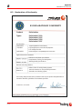
8.3
Declaration of Conformity 78
9 Your Notes 79

Product Overview
Page 6
B0190806
I
1
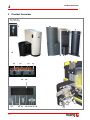
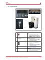
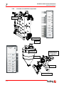
1 Product Overview
4
14
6, 7
15
16
13
18
17
19
20
21 22 23 24
25
26
5
3
2a
1
Key switch for
screw discharge
2b
8
9
10
11
12

Product Overview
Fröling Heizkessel- und Behälterbau Ges.m.b.H, Industriestraße 12, A-4710 Grieskirchen, Austria Page 7
Tel +43 (0) 7248 606-0 Fax +43 (0) 7248 606-600 info@froeling.com www.froeling.com
B0190806
1
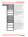
Pos. Component Symbol
1 P2 Pellet Boiler with heat-exchanger
2a Stoker assembly for screw discharge
2b Stoker assembly for suction unit discharge
3 Key switch to lock screw outputs of the pellet module (only for screw discharge)
4 Additional insulating door for reduced heat radiation
5 Combustion chamber door with viewing window
6 Ashcan with wheels and handle (ash screw module)
7 Ash drawer, front and rear (ash drawer module); no illustration
8 Heat-exchange system: Turbulator with automatic heat exchanger cleaning mechanism
9 Pellets lock with two chamber system as protection against blowback
10 Stoker screw for introducing fuel with drive motor
11 Ignition fan with automatic ignition
12 Upper part of gravity shaft to secure fuel for secure fuel delivery (only for direct screw discharge)
o.A. For suction systems: cyclone container with suction motor (attached directly at the pellet lock)
13 Main switch: switches the system on and off
14 HZG 0 / ÖL (Auto/Manual/Off)
15 HEATING 1-4 (Auto/Manual/Off)
16 PUMP 1-3 (Auto/Manual/Off)
17 BLOWER FAN (Auto/Manual/Off)
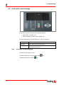
18 Lambdatronic P 3100 control system with two-row display for showing operating status
19 The corresponding LED illuminates when there is activity from positions 14-17
20 Status LED (Operating Status): - slow, green flashing light: Boiler activated
- fast green flashing light: Boiler deactivated
- red flashing light: Fault
21 Start key: Switch on boiler
22 Stop key: Switch off boiler
23 Back key: Return from a submenu or undo an entry
BACK
24 Up arrow key: Move the arrow up in the menu, increase or activate parameters
25 Down arrow key: Move the arrow down in the menu, decrease or deactivate parameters
26 Enter key: Go to submenus, call up or confirm entries
ENTER

Safety
Safety Information
Page 8
B0190806
I
2
2 Safety
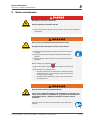
2.1 Safety Information
Non-permitted use!
Incorrect use of the boiler can cause severe injuries and damage!
The instructions and information provided in the instructions
should be observed!
Details on procedure for operation, maintenance and cleaning, as
well as troubleshooting for the boiler are included in the
individual instructions. Any further work should be carried out by
authorised heating engineers or by Fröling customer services.
External influences!
Negative external influences, such as insufficient combustion air or
non-standard fuel can cause serious faults in combustion (e.g.
spontaneous combustion of carbonisation gases or flash fires) which
can in turn cause serious accidents!
Instructions and information for versions and minimum values, as
well as norms and guidelines for heating components in the
instructions must be observed!
Severe injuries and damage can be caused by an inadequate flue gas
system!
Problems with the flue system, such as poor cleaning of the flue pipe
or insufficient chimney draught can cause serious faults in
combustion (such as spontaneous combustion of carbonisation gases
or flash fires)!
You can only be guaranteed of optimum performance from the boiler if the
flue gas system is running smoothly!

Safety
Permitted Uses
Fröling Heizkessel- und Behälterbau Ges.m.b.H, Industriestraße 12, A-4710 Grieskirchen, Austria Page 9
Tel +43 (0) 7248 606-0 Fax +43 (0) 7248 606-600 info@froeling.com www.froeling.com
B0190806
2
2.2 Permitted uses
The boiler should only be operated when it is in full working order.
It should be operated in accordance with the instructions, observing
safety precautions, and you should ensure you are aware of the
potential hazards. Ensure that any faults, which might impact safety are
traced and removed immediately.
The P2 Pellet Boiler is intended exclusively for heating up
heating water. Use only the fuels specified in 2.2.1 below.
The manufacturer or supplier is not liable for any damages
resulting from non-permitted uses.
2.2.1 Permitted fuel
Wood pellets from natural wood with a diameter of 6mm
Applicable standards:
Austria: ÖNORM M 7135 - HP 1 and/or DINplus certification
program
Germany: DIN 51731 - HP 5, DINplus certification program and/or
ÖNORM M 7135 - HP 1
Applies generally:
Before refilling the store, check for pellet dust and clean if necessary.
Non-permitted fuels!
Burning non-permitted fuels lead to a build-up of aggressive
sedimentation and condensation, which can lead to damage to the
boiler and also voids the warranty!
2.2.2 Who can operate the boiler
Only trained operators are permitted to operate the boiler.
No unauthorized access to the boiler room.
Danger: Personal injury and damage to property.
It is the responsibility of the operator to ensure that unauthorized persons,
especially children, are kept away from the boiler.
§

Safety
Design Information
Page 10
B0190806
I
2
2.3 Design Information
It is generally forbidden to carry modifications to the boiler or to change
or deactivate safety equipment.
In addition to the operating instructions and the applicable regulations
for the country in which the boiler will be operated for installation and
operation of the boiler system, all fire, police, and electrical regulations
must be observed.
2.3.1 Official approval and obligation to report
Each heating system must be officially approved.
When installing or modifying a heating system, you must inform the
inspectors from the supervisory authority and get authorisation from the
building authorities.
Austria: Report to the construction authorities of the community or
magistrate
Germany: Report new installations to an approved chimney sweeper and to
the building authorities.
2.3.2 Requirements for heating water
The requirements for heating water are based on the following
standards:
Applicable standards:
Austria: ÖNORM H 5195-1
Germany: VDI 2035
If the system is topped up or refilled:
Prepare (soften) the water to prevent boiler scaling.
2.3.3 Ventilating the Boiler Room
The openings for the supply air and the exhaust air should be arranged
as nearly opposite each other as possible to achieve a good thermal
draught effect.
The supply air must be drawn in directly from outside. The exhaust
air must be discharged directly outside.
Provided they are not contradicted by the relevant building regulations
room where the boiler is to be installed, the following standards apply:
Applicable standards:
- TRVB H 118
- ÖNORM H 5170
§
§

Safety
Design Information
Fröling Heizkessel- und Behälterbau Ges.m.b.H, Industriestraße 12, A-4710 Grieskirchen, Austria Page 11
Tel +43 (0) 7248 606-0 Fax +43 (0) 7248 606-600 info@froeling.com www.froeling.com
B0190806
2
Rule of thumb:
Provide a supply air cross-section of 2 cm
2
per kW of boiler rated output,
as per ÖNORM H 5170, but a total cross-section of at least 200 cm
2
2.3.4 Heating System Installation/ Standards
The following standards govern the installation of heating systems:
Applicable standards:
ÖNORM / DIN EN 12828 Heating Systems in Buildings
The following prior standards still apply:
Austria: - Closed systems as per ÖNORM B 8131
- open systems as per ÖNORM B 8130
Germany: - closed systems as per DIN 4751 Part 2
- open systems as per DIN 4751 Part 1
A storage tank with the proper dimensions will guarantee the best boiler
operating values during the entire heating period.
Return feed lift
If the heated water return feed is under the minimum return
temperature, a portion of the heated water outfeed will be mixed in.
Below dew point / condensation forms during operation without
return feed lift!
Condensation water and fuel residue combine to form an aggressive
condensate, leading to damage to the boiler!
Regulations demand the use of a return feed lift!
§

Safety
Design Information
Page 12
B0190806
I
2
2.3.5 Chimney connection / chimney system
The standard EN 303-5 specifies that the entire flue gas system must be
designed to prevent, wherever possible, damage caused by seepage,
insufficient feed pressure and condensation.
It should be noted here that flue gas temperatures of less than 160 K
above room temperature can occur within the permitted operating range
of the boiler.
The flue gas temperatures (when cleaned) and the additional flue gas
values can be found in the technical specification sheets.
Page 12, Boiler data for constructing the flue gas system
Install the connection to the chimney via the shortest path, as far as
possible under 30 – 45°. Insulate the connector.
The entire flue gas system (chimney and connection) must be worked
out as per ÖNORM / DIN EN 13384-1 or prior standards ÖNORM M
7515 / DIN 4705-1.
In addition, local and other legal regulations apply!
The chimney must be approved by a smoke trap sweeper or
chimney sweeper.
As per TRVB H 118 (only in Austria) an explosion flap must be
installed in the flue pipe or in the chimney.
Draught limiter
We recommend that you install a draught limiter 1
Install the draught limiter directly under the mouth of the flue line,
as there is always low pressure there.
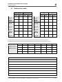
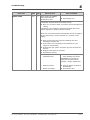
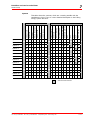
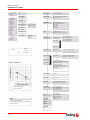
Boiler data for constructing the flue gas system
Component Unit P2-10 P2-15 P2-20 P2-25
Flue gas temperature NL °C 150 150 155 160
Flue gas mass flow NL
PL
kg/h
38
12
38
12
51
16
64
20
Flue gas mass flow NL
PL
kg/s
0.0106
0.0033
0.0106
0.0033
0.0142
0.0044
0.0178
0.0056
Feed pressure required NL
PL
Pa
7
4
7
4
7.5
4.5
8
5
Feed pressure required NL
PL
mbar
0.07
0.04
0.07
0.04
0.075
0.045
0.08
0.05
Flue pipe diameter mm 130 130 130 130
NL = Nominal Load, PL = Partial Load
1

Safety
Safety Devices
Fröling Heizkessel- und Behälterbau Ges.m.b.H, Industriestraße 12, A-4710 Grieskirchen, Austria Page 13
Tel +43 (0) 7248 606-0 Fax +43 (0) 7248 606-600 info@froeling.com www.froeling.com
B0190806
2
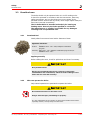
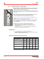
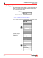
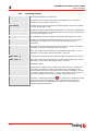
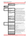
2.4 Safety Devices
1 STOP key
In case of overheating, shut down the
boiler
The pumps continue to run!
Always end heating with the
STOP key. Never use the main
switch.
2 Key switch (for screw
discharge)
Disengages power from the combustion
unit’s drive components.
CAUTION: The power is still on
in the pellet module!
3 Main switch
For shutting down the entire system
The power to all components is
switched off.
CAUTION: The power is still on
in the pellet module!
4 Safety temperature limiter
(STL)
Page 14, Devices for preventing the
boiler from overheating
5 Fuse Fuse the controls and electrical
components
When changing fuses, fit fuses with
the rated current specified.
2
4
1
3 5

Safety
Safety Devices
Page 14
B0190806
I
2
2.4.1 Devices for preventing the boiler from overheating
Thermal discharge safety device
At around 100 °C a valve opens and sends cold water to the safety
heat-exchanger to decrease the temperature.
Safety Temperature Limiter STL
Stops combustion at a max. boiler temperature of 100 °C. The pumps
continue to run!
As soon as the temperature has gone back down, the STL (1) can
be mechanically unlocked.
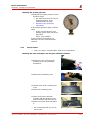
Safety valve
Protection against over-heating/ excessive pressure:
When the boiler pressure reaches a maximum of 3 bar, the safety valve
opens and the heating water is released in the form of steam.
2.5 Safety information for installation room
1) Danger of fire due to flammable materials!
No flammable materials should be stored near the boiler.
2) Damage due to impurities in combustion air!
Do not use any hydrogen halides or any cleaning agents containing
chlorine in the room where the boiler is installed.
3) Keep the air suction opening of the boiler free of dust.
4) The room where the boiler is installed must be frost-proof.
1
1

Safety
Other risks
Fröling Heizkessel- und Behälterbau Ges.m.b.H, Industriestraße 12, A-4710 Grieskirchen, Austria Page 15
Tel +43 (0) 7248 606-0 Fax +43 (0) 7248 606-600 info@froeling.com www.froeling.com
B0190806
2
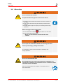
2.6 Other risks
Do not touch the hot surface!
Hot parts and the flue pipe can cause serious burns!
Protective gloves should generally be worn when working on
the boiler.
Only operate the boiler using the handles provided for this
purpose.
Insulate the flue pipes or simply avoid touching them during
operation.
Before carrying out work in the boiler:
Turn off the boiler with the key and allow it to cool down
Then switch off the main switch.
Never turn off the boiler directly with the main
switch!
Do not open the combustion chamber door during operation!
This may cause injury, damage and smoke!
It is forbidden to open the doors behind the insulating door
during operation!
Do not use unauthorised fuel!
Non-standard fuels can cause serious faults in combustion (e.g.
spontaneous combustion of carbonisation gases / flash fires) which
can lead to serious accidents!
Only use fuels specified in the chapter on “Permitted Uses” in
these instructions.

Safety
Emergency procedure
Page 16
B0190806
I
2
2.7 Emergency procedure
2.7.1 System overheating
If the system overheats and the safety devices fail to operate, proceed
as follows:
Keep all the doors on the boiler closed.
Turn off the boiler with the key
Under no circumstances use the main switch!
Open all mixer taps, switch on all pumps.
Fröling heating circuit control takes over this function in
automatic operation.
Leave the boiler room and close the door.
Open any available radiator thermostat valves
If the temperature does not drop, inform the installer or Fröling
customer services:
Page 77, 8.2 Manufacturer address
2.7.2 Smell of flue gas
Smell of flue gas!
Flue gases can cause fatal poisoning!
Keep all the doors on the boiler closed.
Turn off the boiler with the key
Under no circumstances use the main switch!
Air the room where the boiler is installed
Close the fire protection door and doors to living areas.
2.7.3 Fire
Fire!
In case of fire, there is risk of burns and explosions!
Turn off the boiler
Use a tested fire extinguisher for fire class AB to fight the fire
AB powder

Operating the System
Initial startup
Fröling Heizkessel- und Behälterbau Ges.m.b.H, Industriestraße 12, A-4710 Grieskirchen, Austria Page 17
Tel +43 (0) 7248 606-0 Fax +43 (0) 7248 606-600 info@froeling.com www.froeling.com
B0190806
3
3 Operating the System
3.1 Initial startup
Initial startup should be carried out with an authorised installer or with Fröling
customer services.
The individual steps of the initial setup procedure are explained in the
chapter on “Installers and service technicians”
Page 59, 7.4 Initial startup
If condensation escapes during the initial heatup phase, this does not
indicate a fault.
If this occurs, clean up using a cleaning rag.
3.2 Filling/ refilling the store with fuel
Damage and injuries can occur if the store is filled when the boiler is
on!
Turn off the boiler with the key
Allow the boiler to cool down for at least half an hour.
When the boiler has cooled down:
Close all opening to the store to seal out dust
Fill the store with pellets
Only use permitted pellets
Page 9, 2.2.1 Permitted fuel

Operating the system
Heating up the boiler
Page 18
B0190806
s
3
3.3 Heating up the boiler
3.3.1 Switching on the system
Switch on the main switch on the controls
After the system check by the controls, the system is ready for
operation
3.3.2 Switching on the boiler
All selector switches must be set to “Auto”.
Press the key
The heating system is controlled via the control system according
to the selected mode.
3.3.3 Controlling the boiler
See chapter 4 - Lambdatronic P 3100 control system
3.3.4 Switching off the boiler
Press the key
The boiler follows the shut-down program and switches to
“Burner OFF” status.
The control system then only controls the connected heating
components
3.3.5 Switching off the System
ATTENTION! Only switch off when the boiler has cooled
down.
Switch off the main switch on the controls
The controls are switched off
The system components are powered down.
Caution: The power is still on in the pellet module!

Operating the system
Heating up the boiler
Fröling Heizkessel- und Behälterbau Ges.m.b.H, Industriestraße 12, A-4710 Grieskirchen, Austria Page 19
Tel +43 (0) 7248 606-0 Fax +43 (0) 7248 606-600 info@froeling.com www.froeling.com
B0190806
3
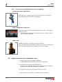
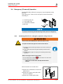
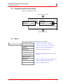
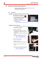
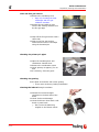
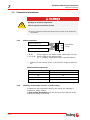
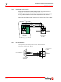
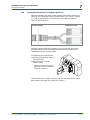
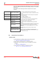
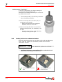
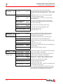
3.4 Emergency (Firewood) Operation
The P2 Pellet Boiler allows for emergency manual operation using
firewood.
This requires the “insert set for emergency firewood operation.”
consisting of:
- 1 x insertion grate (1)
- 1 x cover plate (2)
- 4 x combustion chamber
guards (3)
A properly functioning thermal discharge safety device is obligatory!
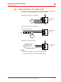
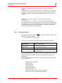
3.4.1 Modifying the boiler for emergency operation using firewood
Do not carry out modifications when the boiler is hot!
Hot parts and the flue pipe can cause serious burns!
Protective gloves should generally be worn when working on
the boiler.
Only operate the boiler using the handles provided for this
purpose.
Insulate the flue pipes or simply avoid touching them during
operation.
Before carrying out work in the boiler:
Turn off the boiler with the key and allow it to cool down
Then switch off the main switch.
Never turn off the boiler directly with the main
switch!
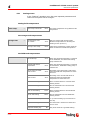
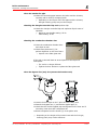
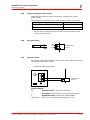
When the boiler has cooled down:
Remove the combustion set from the
pellet burner
Remove the upper guide plate with
the fuse receptacle
Remove the middle guide plate
1.
1
2
3

Operating the system
Heating up the boiler
Page 20
B0190806
s
3
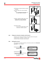
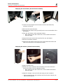
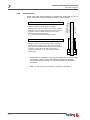
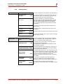
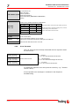
Exchange the guide plate and replace
as shown
Put the steel cover onto the guide
plate
The combustion gases path over
the guide plates is blocked.
2.
Hang 2 chamber guards each on the
left and right in the combustion
chamber on the bolts provided
3.
Insert the grate
It sits on the angled edges of the
combustion chamber guards.
4.
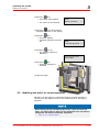
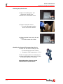
3.4.2 Filling the combustion chamber with firewood
Place a layer of firewood broken into small pieces on the grate
Place paper, cardboard or similar on top
Fill the rest of the space with firewood
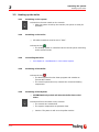
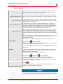
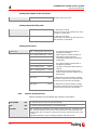
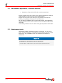
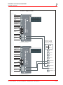
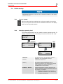
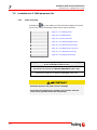
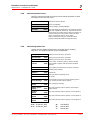
3.4.3 Setting the controls
For emergency firewood operation, the mode must be set to “Firewood
operation” on the controls:
Press the key
ENTER
The arrow on the display
points to “Set”
Press the key
ENTER
Press the key until the arrow
points to mode
For example, winter
operation.
Mode
Winter operation
Set
Error display
Page is loading ...
Page is loading ...
Page is loading ...
Page is loading ...
Page is loading ...
Page is loading ...
Page is loading ...
Page is loading ...
Page is loading ...
Page is loading ...
Page is loading ...
Page is loading ...
Page is loading ...
Page is loading ...
Page is loading ...
Page is loading ...
Page is loading ...
Page is loading ...
Page is loading ...
Page is loading ...
Page is loading ...
Page is loading ...
Page is loading ...
Page is loading ...
Page is loading ...
Page is loading ...
Page is loading ...
Page is loading ...
Page is loading ...
Page is loading ...
Page is loading ...
Page is loading ...
Page is loading ...
Page is loading ...
Page is loading ...
Page is loading ...
Page is loading ...
Page is loading ...
Page is loading ...
Page is loading ...
Page is loading ...
Page is loading ...
Page is loading ...
Page is loading ...
Page is loading ...
Page is loading ...
Page is loading ...
Page is loading ...
Page is loading ...
Page is loading ...
Page is loading ...
Page is loading ...
Page is loading ...
Page is loading ...
Page is loading ...
Page is loading ...
Page is loading ...
Page is loading ...
Page is loading ...
Page is loading ...
-
 1
1
-
 2
2
-
 3
3
-
 4
4
-
 5
5
-
 6
6
-
 7
7
-
 8
8
-
 9
9
-
 10
10
-
 11
11
-
 12
12
-
 13
13
-
 14
14
-
 15
15
-
 16
16
-
 17
17
-
 18
18
-
 19
19
-
 20
20
-
 21
21
-
 22
22
-
 23
23
-
 24
24
-
 25
25
-
 26
26
-
 27
27
-
 28
28
-
 29
29
-
 30
30
-
 31
31
-
 32
32
-
 33
33
-
 34
34
-
 35
35
-
 36
36
-
 37
37
-
 38
38
-
 39
39
-
 40
40
-
 41
41
-
 42
42
-
 43
43
-
 44
44
-
 45
45
-
 46
46
-
 47
47
-
 48
48
-
 49
49
-
 50
50
-
 51
51
-
 52
52
-
 53
53
-
 54
54
-
 55
55
-
 56
56
-
 57
57
-
 58
58
-
 59
59
-
 60
60
-
 61
61
-
 62
62
-
 63
63
-
 64
64
-
 65
65
-
 66
66
-
 67
67
-
 68
68
-
 69
69
-
 70
70
-
 71
71
-
 72
72
-
 73
73
-
 74
74
-
 75
75
-
 76
76
-
 77
77
-
 78
78
-
 79
79
-
 80
80


Froling P2-15 Operating Instructions Manual
- Type
- Operating Instructions Manual
Ask a question and I''ll find the answer in the document
Finding information in a document is now easier with AI
Related papers
-
Froling S3 Turbo Operating Instructions Manual
-
Froling P4 Pellet 8 - 60 Operating Instructions Manual
-
-
-
-
-
-
-
-
Other documents
-
 Austrian Audio CC8 Cardioid Condenser Microphone User guide
-
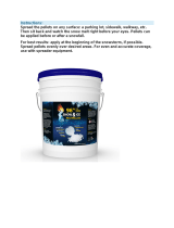 Eco Clean 96CCHLOR-25 User manual
-
Kampmann Compact controller, type 30158 Installation guide
-
Centrometal PelTec Technical Instructions
-
BALTUR Minicomist 7 User manual
-
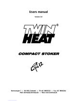 Twin Heat COMPACT STOKER Cpi12 Instructions Manual
-
eta PelletsCompact Series Operation
-
 Pelltech PV50b User manual
-
 LOHBERGER Aqua Insert+P Operating instructions
-
 Cichewicz Futura 35 User manual


