Onan BGM Installation guide
- Category
- Power generators
- Type
- Installation guide
This manual is also suitable for

Caution: This document contains mixed page sizes (8.5 x 11 or 11 x
17), which may affect printing. Please adjust your printer settings
according to the size of each page you wish to print.

Printed in U.S.A.
965−0633
5−97
BGM, NHM
Installation Manual

The engine exhaust from this product
contains chemicals known to the State
of California to cause cancer, birth
defects or other reproductive harm.
!!

i
Table of Contents
SECTION TITLE PAGE
SAFETY PRECAUTIONS ii. . . . . . . . . . . . . . . . . . . . . . . . . . . . . . . . . . . . . . . . . . . .
1 INTRODUCTION 1-1. . . . . . . . . . . . . . . . . . . . . . . . . . . . . . . . . . . . . . . . . . . . . . . . . .
About this Manual 1-1. . . . . . . . . . . . . . . . . . . . . . . . . . . . . . . . . . . . . . . . . . . . . . .
Installation Codes and Standards for Safety 1-1. . . . . . . . . . . . . . . . . . . . . . . . .
2 GENERAL SPECIFICATIONS 2-1. . . . . . . . . . . . . . . . . . . . . . . . . . . . . . . . . . . . . .
3 MOUNTING 3-1. . . . . . . . . . . . . . . . . . . . . . . . . . . . . . . . . . . . . . . . . . . . . . . . . . . . . .
General 3-1. . . . . . . . . . . . . . . . . . . . . . . . . . . . . . . . . . . . . . . . . . . . . . . . . . . . . . . .
Compartment Mount 3-1. . . . . . . . . . . . . . . . . . . . . . . . . . . . . . . . . . . . . . . . . . . . .
Under-Floor Mount 3-4. . . . . . . . . . . . . . . . . . . . . . . . . . . . . . . . . . . . . . . . . . . . . .
4 VENTILATION AND ACOUSTICS 4-1. . . . . . . . . . . . . . . . . . . . . . . . . . . . . . . . . . .
Ventilation 4-1. . . . . . . . . . . . . . . . . . . . . . . . . . . . . . . . . . . . . . . . . . . . . . . . . . . . . .
Acoustics 4-1. . . . . . . . . . . . . . . . . . . . . . . . . . . . . . . . . . . . . . . . . . . . . . . . . . . . . . .
5 EXHAUST SYSTEM 5-1. . . . . . . . . . . . . . . . . . . . . . . . . . . . . . . . . . . . . . . . . . . . . .
General 5-1. . . . . . . . . . . . . . . . . . . . . . . . . . . . . . . . . . . . . . . . . . . . . . . . . . . . . . . .
Muffler Recommendations 5-1. . . . . . . . . . . . . . . . . . . . . . . . . . . . . . . . . . . . . . . .
Exhaust Installation Guidelines 5-1. . . . . . . . . . . . . . . . . . . . . . . . . . . . . . . . . . . .
Tailpipe Recommendations 5-3. . . . . . . . . . . . . . . . . . . . . . . . . . . . . . . . . . . . . . .
6 FUEL SYSTEM 6-1. . . . . . . . . . . . . . . . . . . . . . . . . . . . . . . . . . . . . . . . . . . . . . . . . . .
General 6-1. . . . . . . . . . . . . . . . . . . . . . . . . . . . . . . . . . . . . . . . . . . . . . . . . . . . . . . .
Gasoline Fuel System 6-1. . . . . . . . . . . . . . . . . . . . . . . . . . . . . . . . . . . . . . . . . . . .
LPG Liquid Withdrawal Fuel System 6-3. . . . . . . . . . . . . . . . . . . . . . . . . . . . . . .
7 ELECTRICAL CONNECTIONS 7-1. . . . . . . . . . . . . . . . . . . . . . . . . . . . . . . . . . . . .
General 7-1. . . . . . . . . . . . . . . . . . . . . . . . . . . . . . . . . . . . . . . . . . . . . . . . . . . . . . . .
AC Wiring 7-1. . . . . . . . . . . . . . . . . . . . . . . . . . . . . . . . . . . . . . . . . . . . . . . . . . . . . .
DC Wiring 7-5. . . . . . . . . . . . . . . . . . . . . . . . . . . . . . . . . . . . . . . . . . . . . . . . . . . . . .
Batteries 7-6. . . . . . . . . . . . . . . . . . . . . . . . . . . . . . . . . . . . . . . . . . . . . . . . . . . . . . .
8 INITIAL START AND CHECKS 8-1. . . . . . . . . . . . . . . . . . . . . . . . . . . . . . . . . . . . .
Pre-Start Checks 8-1. . . . . . . . . . . . . . . . . . . . . . . . . . . . . . . . . . . . . . . . . . . . . . . .
Initial Start-Up/Inspection 8-1. . . . . . . . . . . . . . . . . . . . . . . . . . . . . . . . . . . . . . . . .
Installation Review 8-3. . . . . . . . . . . . . . . . . . . . . . . . . . . . . . . . . . . . . . . . . . . . . . .

ii
Safety Precautions
Thoroughly read the OPERATOR’S MANUAL
before operating the genset. Safe operation and
top performance can be obtained only when
equipment is operated and maintained proper-
ly.
The following symbols in this manual alert you to
potential hazards to the operator, service person
and equipment.
alerts you to an immediate hazard
which will result in severe personal injury or
death.
WARNING
alerts you to a hazard or unsafe
practice which can result in severe personal in-
jury or death.
CAUTION
alerts you to a hazard or unsafe
practice which can result in personal injury or
equipment damage.
Electricity, fuel, exhaust, moving parts and batteries
present hazards which can result in severe person-
al injury or death.
GENERAL PRECAUTIONS
• Keep ABC fire extinguishers handy.
• Make sure all fasteners are secure and torqued
properly.
• Keep the genset and its compartment clean.
Excess oil and oily rags can catch fire. Dirt and
gear stowed in the compartment can restrict
cooling air.
• Before working on the genset, disconnect the
negative (- ) battery cable at the battery to pre-
vent starting.
• Use caution when making adjustments while
the genset is running—hot, moving or electri-
cally live parts can cause severe personal inju-
ry or death.
• Used engine oil has been identified by some
state and federal agencies as causing cancer
or reproductive toxicity. Do not ingest, inhale,
or contact used oil or its vapors.
• Benzene and lead in some gasolines have
been identified by some state and federal
agencies as causing cancer or reproductive
toxicity. Do not to ingest, inhale or contact gas-
oline or its vapors.
• Do not work on the genset when mentally or
physically fatigued or after consuming alcohol
or drugs.
• Carefully follow all applicable local, state and
federal codes.
GENERATOR VOLTAGE IS DEADLY!
• Generator output connections must be made
by a qualified electrician in accordance with ap-
plicable codes.
• The genset must not be connected to the public
utility or any other source of electrical power.
Connection could lead to electrocution of utility
workers and damage to equipment. An ap-
proved switching device must be used to pre-
vent interconnections.
• Use caution when working on live electrical
equipment. Remove jewelry, make sure cloth-
ing and shoes are dry and stand on a dry wood-
en platform.

iii
FUEL IS FLAMMABLE AND EXPLOSIVE
• Do not smoke or turn electrical switches ON or
OFF where fuel fumes, tanks or equipment are
present or in areas sharing ventilation. Keep
flame, sparks, pilot lights, arc-producing equip-
ment and switches and all other sources of igni-
tion well away.
• Fuel lines must be secured, free of leaks and
separated or shielded from electrical wiring.
• Use approved non-conductive flexible fuel
hose for fuel connections at the genset.
• Leaks can lead to explosive accumulations of
gas. LPG sinks when released and can accu-
mulate inside housings and basements and
other below-grade spaces. Prevent leaks and
the accumulation of gas.
ENGINE EXHAUST IS DEADLY!
• Learn the symptoms of carbon monoxide poi-
soning in this Manual.
• The exhaust system must be installed in accor-
dance with the genset Installation Manual.
• Do not use engine cooling air to heat a room or
compartment.
• Make sure there is ample fresh air when oper-
ating the genset in a confined area.
BATTERY GAS IS EXPLOSIVE
• Wear safety glasses and do not smoke while
servicing batteries.
• When disconnecting or reconnecting battery
cables, always disconnect the negative (- ) bat-
tery cable first and reconnect it last to reduce
arcing.
MOVING PARTS CAN CAUSE SEVERE
PERSONAL INJURY OR DEATH
• Do not wear loose clothing or jewelry near mov-
ing parts such as PTO shafts, fans, belts and
pulleys.
• Keep hands away from moving parts.
• Keep guards in place over fans, belts, pulleys,
etc.
Mobile-6

1-1
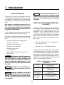
1. Introduction
ABOUT THIS MANUAL
This manual is a guide for the installation of the Se-
ries BGM and NHM generator sets (gensets). Prop-
er installation is essential for top performance.
Read through this manual before starting the instal-
lation.
Note: Manuals are updated from time to time to re-
flect changes in the equipment and its specifica-
tions. For this reason, only the copy of the installa-
tion manual supplied with the genset should be used
as a guide for the installation.
See the Operator’s Manual for operation and main-
tenance and the Service Manual for service.
Consider the following requirements before instal-
ling the set. Each topic is covered in the following
text.
• Level and supportive mounting surface
• Adequate cooling air
• Adequate fresh induction air
• Discharge of circulated air
• Electrical connections
• Fuel installation
• Accessibility for maintenance and service
• Noise levels
WARNING
This genset is not a life support sys-
tem. It can stop without warning. Children, per-
sons with physical or mental limitations, and
pets could suffer personal injury or death. A
personal attendant, redundant power or an
alarm system must be used if genset operation
is critical.
WARNING
This genset is not for marine use.
On a vessel, can cause asphyxiation, explosion
or electrocution.
WARNING
Improper installation can result in
severe personal injury, death and equipment
damage. The installer must be qualified to per-
form the installation of electrical and mechani-
cal equipment.
CAUTION
Unauthorized modifications or re-
placement of fuel, exhaust, air intake or speed
control system components that affect engine
emissions are prohibited by law in the State of
California.
INSTALLATION CODES AND STANDARDS
FOR SAFETY
The builder of the RV bears sole responsibility for
the selection of the appropriate genset, for its prop-
er installation and for obtaining approvals from the
authorities (if any) having jurisdiction over the
installation. These sets meet the basic require-
ments of the Standard for Safety for Engine Gener-
ator Sets for Recreational Vehicles, ANSI/RVIA
EGS-1. They are suitable for installation in accor-
dance with:
• NFPA No. 70, Article 551—Recreational Ve-
hicles and RV Parks
• NFPA No. 501C—Recreational Vehicles
Federal, State and local codes, such as the Califor-
nia Administrative Code—Title 25 (RV installation),
might also be applicable. Installation codes and rec-
ommendations can change from time-to-time and
are different in different countries, states and mu-
nicipalities. It is recommended that the standards in
Table 1-1 be obtained for reference.
TABLE 1-1. REFERENCE CODES AND
STANDARDS
NFPA Nos.
70 & 501C
National Fire Protection Association
470 Atlantic Avenue
Boston, MA 02210
ANSI/RVIA-EGS-1
Recreational Vehicle Industry Association
14650 Lee Road
Chantily, VA 22021
California Adminis-
trative Code—Title
25, Chapter 3
State of California Documents Section
P.O. Box 1015
North Highlands, CA 95660
CAN/CSA-Z240
Recreational Ve-
hicles
Canadian Standards Association
Housing and Construction Materials Section
178 Rexdale Blvd.
Rexdale, Ontario, Canada M9W 1R3

1-2
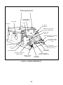
FIGURE 1-1. MARQUIS GENERATOR SET
SPARK PLUGS (TOP ACCESS
TO FRONT AND REAR PLUG)
REMOTE CABLE
CONNECTOR
AC CIRCUIT
BREAKERS
START/STOP
SWITCH
FUEL INLET
.25 INCH HOSE (GASOLINE)
.25 INCH NPTF (LPG)
AC OUTPUT LEADS
60 INCHES (1.5 M)
LONG
.50 INCH FLEXIBLE
CONDUIT CONNECTION
VOLTAGE
REGULATOR
POSITIVE (+) BATTERY
CONNECTION
OIL DRAIN VALVE
OIL FILL AND
CHECK
NAMEPLATE
MUFFLER
OIL FILTER
FUSE
SUMMER/WINTER
ADJUSTMENT
NEGATIVE (-) BATTERY
CABLE CONNECTION
GOVERNOR
CONTROLLER
FUEL PUMP (FUEL SOLENOID,
LPG GENSETS)

2-1
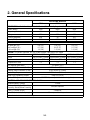
2. General Specifications
GASOLINE MODELS
BGM NHM NHM
GENERATOR: 4-Pole Revolving Field, Self-Excited, Electronically Regulated, 1-Phase
Power (watts) 5500 6000 6800
Frequency (Hertz) 60 60 60
Voltage 120 120 120
Current (amperes) 45.8 50 56.7
Speed (RPM) 1800 1800 1800
FUEL CONSUMPTION:
No load gph (l/h)
Half load gph (l/h)
Full load gph (l/h)
0.4 (1.5)
0.7 (2.6)
1.0 (3.8)
0.4 (1.5)
0.6 (2.27)
1.3 (4.9)
0.4 (1.5)
0.7 (2.6)
1.3 (4.9)
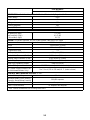
ENGINE: 2-Cylinder Opposed, 4-Cycle, Spark-Ignited, Side-Valve, Air Cooled
Bore 3.250 inches (83 mm) 3.563 inches (90 mm) 3.563 inches (90 mm)
Stroke 2.875 inches (73 mm) 3.000 inches (76 mm) 3.000 inches (76 mm)
Displacement 48 inches
3
(782 cc) 60 inches
3
(980 cc) 60 inches
3
(980 cc)
Compression Ratio 7:1 7:1 7:1
Oil Capacity (with filter)* 3.5 quarts (3.3 l)
Intake Valve Clearance (Cold) 0.005 inches (0.13 mm)
Exhaust Valve Clearance (Cold) 0.013 inches (0.33 mm)
Spark Plug Gap 0.025 inches (0.64 mm)
Spark Plug Tightening Torque 8 lbs-ft (10 N-m)
Ignition Timing 12° BTDC (non-adjustable electronic ignition)
CONTROL AND CRANKING SYSTEM: 12 VDC
Nominal Battery Voltage 12 volts
Minimum Battery Cold Cranking
Capacity: Above/Below Freezing
360/450 amperes
Fuse F1 (control circuit) 5 amperes
Fuse F2 (autochoke/fuel pump) 10 amperes mini-bayonet
* -See
Periodic Maintenance
for oil filling instructions.

2-2
LPG MODELS
NHM
GENERATOR: 4-Pole Revolving Field, Self-Excited, Electronically Regulated, 1-Phase
Power (watts) 6500
Frequency (Hertz) 60
Voltage 120
Current (amperes) 54.2
Speed (RPM) 1,800
FUEL CONSUMPTION:
No load lbs/h (kg/h)
Half load lbs/h (kg/h)
Full load lbs/h (kg/h)
2.1 (.96)
4.1 (1.86)
6.6 (3)
ENGINE: 2-Cylinder Opposed, 4-Cycle, Spark-Ignited, Side-Valve, Air Cooled
Bore 3.563 inches (90 mm)
Stroke 3.000 inches (76 mm)
Displacement 60 inches
3
(980 cc)
Compression Ratio 7:1
Oil Capacity (with filter)* 3.5 quarts (3.3 l)
Intake Valve Clearance (Cold) 0.005 inches (0.13 mm)
Exhaust Valve Clearance (Cold) 0.013 inches (0.33 mm)
Spark Plug Gap 0.025 inches (0.64 mm)
Spark Plug Tightening Torque 8 lbs-ft (10 N-m)
Ignition Timing 12° BTDC (non-adjustable electronic ignition)
LPG Vapor Supply Pressure (Va-
por-Withdrawal Models Only)
9 to 13 inch (229 to 330 mm) W. C. (water column)
CONTROL AND CRANKING SYSTEM: 12 VDC
Nominal Battery Voltage 12 volts
Minimum Battery Cold Cranking
Capacity: Above/Below Freezing
360/450 amperes
Fuse F1 (control circuit) 5 amperes
Fuse F2 (fuel solenoid) 10 amperes mini-bayonet
* -See
Periodic Maintenance
for oil filling instructions.

3-1
3. Mounting
GENERAL
Marquis generator sets are designed for compart-
ment and underfloor mounting. Both methods use
the set tray for support. Choose the appropriate
manual section and carefully follow the instructions.
Read this entire manual and exhaust kit and oth-
er kit instructions before installing the genset.
COMPARTMENT MOUNT
In a compartment mount, the set is installed on a
frame that is part of the vehicle. This frame must be
constructed according to safety-approved specifi-
cations (see Compartment Construction in this sec-
tion).
Unless the set will be removed from underneath the
vehicle, make the access opening large enough to
remove the set. Allow extra clearance to access the
following components:
• Oil fill
• Oil drain
• Oil filter
• Oil dipstick
• Air cleaner element
• Spark plugs
• Carburetor
• Start/Stop switch
• Circuit breaker
• DC fuse
Minimum compartment dimensions are shown in
Figure 3-1. Clearances between the generator set
and the compartment are included in these dimen-
sions.
To minimize noise, line the entire genset compart-
ment with a 1/2 to 1 inch (12.7 to 25.4 mm) thickness
of self-extinguishing acoustical material, rated for
250°F (121° C) minimum. Adjust the compartment
height, width and depth dimensions to fit the acous-
tical material. See Figures 3-1 and 3-2.
Allow for air intake and discharge at the bottom of
the generator set. Air inlets to the set compartment
must not allow dirt, rocks, water, or slush to reach
the set. Minimize dust and salt entrance into the
compartment. Make certain to protect the genera-
tor, control, choke, and governor areas. Use baffles
to protect certain areas. (See
Ventilation and
Acoustics
section.)
Compartment Construction
1. Install the generator set in its own compart-
ment. See Figures 3-1 and 3-2.
2. The compartment must provide a vapor-tight,
fire-resistive barrier between the genset and
the interior of the vehicle. Use approved mate-
rials (26 gauge galvanized steel or equivalent).
See the NEC (NFPA 70) and California Title 25
for details.
WARNING
EXHAUST GAS IS DEADLY.
Construct a suitable vapor barrier of ap-
proved materials between the genset and
vehicle interior to keep out exhaust gas.
3. Construct the compartment floor to prevent oil,
fuel or water accumulation. Provide openings
in the compartment floor according to the
Compartment Floor Plan, Figure 3-2.
Do NOT use absorbent soundproofing material
on the compartment floor. The floor should
have as few openings as possible, to reduce
the noise level.
4. Secure the set mounting tray to the support
frame, using four 3/8-16 UNC grade 5 screws
(bottom mounting) or eight 5/16-18 UNC grade
5 screws (side mounting). The mounting bolts
must not extend more than 1/4 inch (6 mm)
through the mounting nut. See Figures 3-1 and
3-2. Torque 3/8” mounting screws to 35 ft lbs
(47 N•m). Torque 5/16” mounting screws to 25
ft lbs (34 N•m).
CAUTION
If the unit mounting plate is not
fastened securely to the vehicle compart-
ment, road vibrations can damage the gen-
erator set components. Use screws long
enough for at least 1-1/2 threads to extend
through the weld nut. The mounting bolts
must not extend more than 1/4 inch (6 mm)
through the weldnut.

3-2
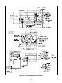
FIGURE 3-1. COMPARTMENT MOUNT OUTLINE
NOTE 1: MINIMUM
UNIT CLEARANCE
FROM COMPART-
MENT SURFACES
SEE NOTE 1
SEE NOTE 1
SEE NOTE 1
RIGHT END VIEW
LEFT END VIEW
TOP VIEW

3-3
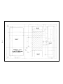
FIGURE 3-2. COMPARTMENT FLOOR PLAN

3-4
UNDER-FLOOR MOUNT
In an under-floor installation, the genset is mounted
below the floor and outside the passenger compart-
ment of the vehicle. This type of installation must
comply with the Installation Codes and Safety Rec-
ommendations (see
Introduction
section). Read
this section for general application information, and
study the proper under-floor housing/exhaust kit in-
structions for more information on under-floor
installations.
The vehicle structure must be able to support the
weight of the generator set (see
Specifications
sec-
tion) when subjected to road vibrations. The vehicle
manufacturer and/or the installer must provide a
structurally sound support frame, using tubing,
angle brackets, or steel-reinforced plywood or other
composition board. Plywood or particle board can
be reinforced with 3-inch (76 mm) or larger washers
or a full metal plate.
Line the floor above the set with 26-gauge galva-
nized steel or a material of comparable strength and
fire resistance (see NFPA 70, NEC and California
Title 25 for complete details).
Generator Set Location
Figure 3-3 shows the most common mounting
areas for an underfloor mount. If the set is mounted
on the curb side, location 1 or 2, protect its genera-
tor end from road splash and debris. If mounted on
the driver’s side, location 3 or 4, protect its engine
end. If possible, drive the vehicle through mud and
slush to test the installation. Refer to shaded areas
of Figure 3-3.
The bottom air inlet opening to the generator set
compartment must not admit dirt, rocks, water or
slush. The entrance of dust and salt into the
compartment must be minimized. Baffles may be
needed to protect certain areas. See the Ventilation
section of this manual for more detailed information.
Access Opening:
Provide an access opening to
the generator set on the side of the vehicle. Make it
large enough to check the following:
• Oil fill
• Oil drain
• Oil filter
• Oil dipstick
• Air cleaner element
• Spark plugs
• Carburetor
• Start/Stop switch
• Circuit breaker
• DC fuse
See Figure 3-1 for size and Figure 3-3 for locations.
Mounting Clearance:
The compartment door
must open the full width of the generator set in
compartment mounts. Under-floor installations re-
quire that access be made from the bottom, or
through a side door. Refer to the correct outline
drawing when installing the set.
CAUTION
Failure to meet Onan review for
modifications of mounting kits or for non-Onan
kit installations can void the intent of NCTI/CSA
approval. Liability for damage or injury and
warranty expenses becomes the responsibility
of the person making the modifications.
Exhaust Kit:
Review the exhaust system kit instal-
lation instructions and check the components sup-
plied in the kit. Plan clearances for shifting or re-
moving exhaust components when the set is re-
moved for inspection or maintenance.
1
3
2
4
FIGURE 3-3. COMMON GENSET MOUNTING AREAS

4-1
4. Ventilation and Acoustics
VENTILATION
Ventilation of the Marquis genset requires:
• Sufficient incoming air (for combustion and
cooling)
• Adequate exhaust of heated air
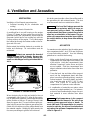
A centrifugal fan in a scroll housing on the engine
(Figure 4-1) draws air from under the set into the
generator end of the compartment, and through the
generator (which has its own cooling fan) over the
cooling surfaces of the engine. Then it discharges
the heated air through the bottom outlet on the en-
gine end of the set.
Make certain that nothing obstructs or restricts air
intake and discharge. Air recirculation must be
minimized.
WARNING
Exhaust gas presents the hazard of
severe personal injury or death. Because dis-
charged cooling air can contain exhaust gas,
never use discharged cooling air to heat the ve-
hicle.
BOTTOM AIR
INLET
AIR
OUTLET
FIGURE 4-1. COOLING SYSTEM
When designing the air inlet and outlet for the set
compartment (see Figure 3-2), allow for the restric-
tion of grilles and ductwork: some expanded metal
grilles provide as little as 60 percent free air inlet
area per square foot. The most efficient grille pro-
vides only 90 percent free inlet area per square foot.
Obtain the free inlet area of the grille material from
the material supplier. Multiply the grille area by the
free area percentage to get the free inlet area.
Air ducting must provide a direct free-airflow path to
the generator set, with minimal bends. The duct
must be smooth and non-restrictive to airflow.
WARNING
Fuel and fuel leakage present the
hazard of fire or explosion, which can cause se-
vere personal injury or death. The ventilation
system should provide a constant flow of air to
expel any accumulation of fuel vapor. The gen-
erator set compartment must be vapor-tight to
the vehicle interior, to keep fumes from entering
the vehicle.
ACOUSTICS
For maximum noise reduction, line the entire gener-
ator compartment with 1 inch (25.4 mm) thickness
of sound absorbing material. Use the following
guidelines to construct the housing.
• Make certain that all joints and corners of the
compartment are vapor-tight to the interior/ cab
of the vehicle. Lining the compartment is less
effective if openings, cracks, doors and joints
are not sealed. Seal the compartment door
edge to eliminate noise leaks around the door
perimeter.
• Cover the back, top and sides of the compart-
ment (not the compartment base) with fiber-
glass or another self-extinguishing, sound-ab-
sorbent material. Sound insulation and adhe-
sive should be rated at 200° F (90° C) mini-
mum. See Figure 4-2 to design the set
compartment for optimum noise reduction.
• A combination of materials can reduce noise
more than a single material can. For instance,
a sheet of lead combined with a layer of acous-
tical material is more effective than either
alone.
WARNING
High temperatures in the compart-
ment can present the hazard of fire, which can
result in severe personal injury or death. To
meet ANSI and CSA temperature rise require-
ments for vehicles, the layer of insulation must
not reduce the minimum compartment size spe-
cified in Figure 3-1.

4-2
SERVICE SIDE ACCESS
PANEL
SELF-EXTINGUISHING ACOUSTICAL MATERIAL
1/2 TO 1 INCH (12.7 TO 25.4 MM THICK)
FIGURE 4-2. NOISE REDUCTION-COMPARTMENT DESIGN RECOMMENDATION

5-1
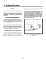
5. Exhaust System
GENERAL
Plan the exhaust system carefully. The exhaust
system must be vapor-tight. Check all applicable
standards, local codes and regulations. Study the
following recommendations. See the instructions
supplied with the exhaust kit for specific mounting
procedures.
MUFFLER RECOMMENDATIONS
The Onan-installed spark arrester muffler is U.S.
Forest Service-approved, and meets code require-
ments. Failure to provide and maintain a spark ar-
rester may violate the law.
Liability for damage or injury, and warranty ex-
penses due to use of unapproved mufflers or instal-
lation modifications becomes the responsibility of
the person installing the substitute muffler or per-
forming the modifications. Contact an Onan distrib-
utor for approved exhaust system parts.
EXHAUST INSTALLATION GUIDELINES
The exhaust system must be placed no closer than
3 inches (76 mm) from combustible material (wood,
felt, cotton, organic fibers, etc.), or be so located, in-
sulated or shielded that it does not raise the temper-
ature of any combustible material more than 117° F
(65° C) above the ambient air inlet temperature.
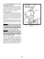
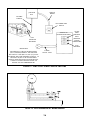
The exhaust system must extend a minimum 1 inch
(25 mm) beyond the perimeter of the vehicle. If the
generator set tailpipe is on the same side of the
coach as the compartment, terminate the tailpipe
aft of the generator set air intake, or reduce the pos-
sibility of exhaust recirculation by directing the ex-
haust down and to the rear.
1 INCH (25 mm)
MINIMUM
LAST TAILPIPE HANGER AS
CLOSE TO END AS PRACTICAL
FIGURE 5-1. TERMINATING THE EXHAUST
TAILPIPE

5-2
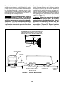
To reduce the chance of damaging the tailpipe and
emitting exhaust gases under the vehicle, make
certain that no part of the exhaust system intrudes
into the departure angle or approach angle of the
vehicle, unless it is protected by a skid bar or other
protection device. The shaded areas in Figure 5-2
illustrate typical mounting locations.
WARNING
Exhaust gas presents the hazard of
severe personal injury or death. Do not mount
any portion of the exhaust system into the ap-
proach or departure angle unless it is adequate-
ly protected. Use only Onan-specified exhaust
equipment with the generator set. Use a suffi-
cient number of hangers to prevent dislocation
of the system.
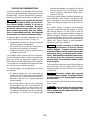
Do not terminate the exhaust tailpipe under the ve-
hicle. Be aware that any vent, window or opening
that can be opened and that is not permanently
sealed from the vehicle living space can be an ave-
nue for carbon monoxide. Do not terminate the tail-
pipe such that it is closer than 6 inches (153 mm) to
any opening into the vehicle interior (door, window,
vent). See Figure 5-2.
WARNING
Exhaust gas presents the hazard of
severe personal injury or death. Do not termi-
nate an exhaust pipe under the vehicle. The tail-
pipe must not terminate so that any vent, win-
dow, or opening into the living area is within the
area shown in Figure 5-2. Keep all openings
closed when the generator set is running.
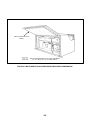
FIGURE 5-2. TAILPIPE INSTALLATION
SEALED WINDOW
TAILPIPE
(RV REAR VIEW)
SKID BARS
GROUND
DEPARTURE
ANGLE
SHADED ZONE IS AREA OF
RECOMMENDED TAILPIPE
INSTALLATION
AXLE LOWER
CLEARANCE
LINE
APPROACH
ANGLE
NO OPENING INTO THE VEHICLE INTERIOR MAY
BE CLOSER THAN 6 INCHES (153 mm) TO THE
END OF THE TAIL PIPE (WITHIN SHADED AREA)
6 in
153 mm
TAILPIPE

5-3
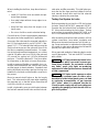
TAILPIPE RECOMMENDATIONS
An exhaust tailpipe is not supplied with the genset,
because length requirements vary between vehicle
manufacturers. Refer to the following recommen-
dations for information and safety considerations.
WARNING
Exhaust gas presents the hazard of
severe personal injury or death. Do not use flex-
ible exhaust tailpipe, because it can leak or
break from road shock or vibration. Do not ter-
minate the exhaust system under the vehicle.
Direct exhaust gases away from any window,
door, or compartment openings. Do not operate
the generator set without an exhaust tailpipe.
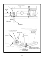
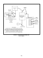
The exhaust pipe can leave the generator set in one
of three directions (see Figures 3-1 and 5-3):
• Straight down through the bottom of the set
(the most common configuration)
• Out the left side of the set (by rotating the ex-
haust tube on the muffler 90 degrees)
• Straight out the back of the set (with the use of
an optional exhaust kit)
If the exhaust exits the side or the rear of the gener-
ator set, discard the original exhaust opening cover
plate and install the appropriate optional cover
plates that enclose the opening around the tailpipe.
Cover plates are included with the optional exhaust
kit, or they may be ordered separately.
The exhaust tailpipe can be attached to the set by
two methods:
• An exhaust tailpipe can be constructed by
welding a 1/4 inch plate steel mounting flange
(see Figure 3-1 for flange dimensions) onto a
minimum 1-3/8 inch O.D. 18-gauge rigid steel
exhaust tailpipe.
• An optional exhaust tube kit, with a mounting
flange welded to one end, can be bolted to the
exhaust pipe on the set (or directly to the muf-
fler when exhausting out the back of the set).
The optional exhaust tube can be cut to the de-
sired length. A 1-1/2 inch O.D. 18-gauge rigid
steel exhaust tailpipe (not supplied) can be slid
over the exhaust tube and clamped in place
with a U-bolt type automotive muffler clamp,
marked 1-3/8 inch.
Place the exhaust gasket (supplied) between the
exhaust flanges. Use 5/16-18 x 1 inch grade 5 bolts
with a flat washer to connect the exhaust flanges.
Tighten the flange mounting bolts to 25 ft-lbs (34
N•m).
Use double rubber, U-shaped, shock-mounted
hangers to support the exhaust system. If the tail-
pipe extends beyond 1-1/2 feet (0.46 m) from the
genset, attach an automotive tailpipe hanger for
additional support. Support the exhaust system at
or near the perimeter of the vehicle to prevent the
pipe from being damaged and pushed up under the
vehicle skirt. Attach hangers to steel framework,
not wood or other floor materials.
CAUTION
Angular mounting of muffler and
tailpipe hanger brackets can result in exhaust
system damage. Properly mounted hanger
brackets will absorb much road shock vibration
and prolong the use of exhaust system compo-
nents. Mount muffler and tailpipe hanger brack-
ets directly above the component supported,
not at an angle. Do not twist the rubber sections
of any hangers.
The exhaust back pressure under full load must not
exceed 2 inches (51 mm) water column (WC) as
measured within 6 inches (154 mm) of the muffler
outlet flange.
CAUTION
Excessive exhaust back pressure
can cause engine damage. If a tailpipe deflector
is used, make sure it is large enough to prevent
back pressure.
Do not connect the genset to the vehicle engine ex-
haust system.
CAUTION
Interconnecting the engine exhaust
systems will allow exhaust condensates and
soot to migrate into the engine that is idle, caus-
ing engine damage.

5-4
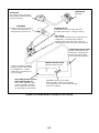
FIGURE 5-3. TYPICAL EXHAUST INSTALLATIONS
MUFFLER
TAILPIPE COVER
OPTIONAL EXHAUST PIPE
FOR REAR EXHAUST
CLAMP
TAILPIPE NOT SUPPLIED
HANGER BRACKET
AT PERIMETER OF
VEHICLE
USE ADDITIONAL HANGERS IF
TAILPIPE EXCEEDS 3 FT (914 mm)
MUFFLER
TAILPIPE NOT
SUPPLIED
TAILPIPE COVER
EXHAUST PIPE
FOR BOTTOM OR
SIDE EXHAUST
TAILPIPE NOT
SUPPLIED
Page is loading ...
Page is loading ...
Page is loading ...
Page is loading ...
Page is loading ...
Page is loading ...
Page is loading ...
Page is loading ...
Page is loading ...
Page is loading ...
Page is loading ...
Page is loading ...
Page is loading ...
Page is loading ...
Page is loading ...
Page is loading ...
-
 1
1
-
 2
2
-
 3
3
-
 4
4
-
 5
5
-
 6
6
-
 7
7
-
 8
8
-
 9
9
-
 10
10
-
 11
11
-
 12
12
-
 13
13
-
 14
14
-
 15
15
-
 16
16
-
 17
17
-
 18
18
-
 19
19
-
 20
20
-
 21
21
-
 22
22
-
 23
23
-
 24
24
-
 25
25
-
 26
26
-
 27
27
-
 28
28
-
 29
29
-
 30
30
-
 31
31
-
 32
32
-
 33
33
-
 34
34
-
 35
35
-
 36
36


Onan BGM Installation guide
- Category
- Power generators
- Type
- Installation guide
- This manual is also suitable for
Ask a question and I''ll find the answer in the document
Finding information in a document is now easier with AI
Related papers
Other documents
-
CUMMINS Microlite 2.3 KV Installation guide
-
-
-
-
 Cummins Power Generation Onan MicroLite 4000 KY Installation guide
-
-
-
-
Toro Muffler Kit, Z Master Z100 Series Mowers Installation guide
-
