DESCRIPTION
The nVent RAYCHEM E-100-LR light kit is used to replace the light on an
E-100-L high-profile lighted end seal or to retrofit a light to an existing
E-100-A high-profile end seal.
This kit may be installed at temperatures as low as –40°F (–40°C).
For easier installation store above freezing until just before installation.
Two units are available:
– E-100-LR1 for 100–120 V
– E-100-LR2 for 200–277 V
Make sure voltage rating of light is the same as that of the heat-tracing
circuit.
For technical support call nVent at (800)545-6258.
TOOLS REQUIRED
• Wire cutters • Rags or dry towel
• Utility knife • Wire strippers
• Marker • Needle nose pliers
• Panduit nVent RAYCHEM CT-100 crimp tool or equivalen
t
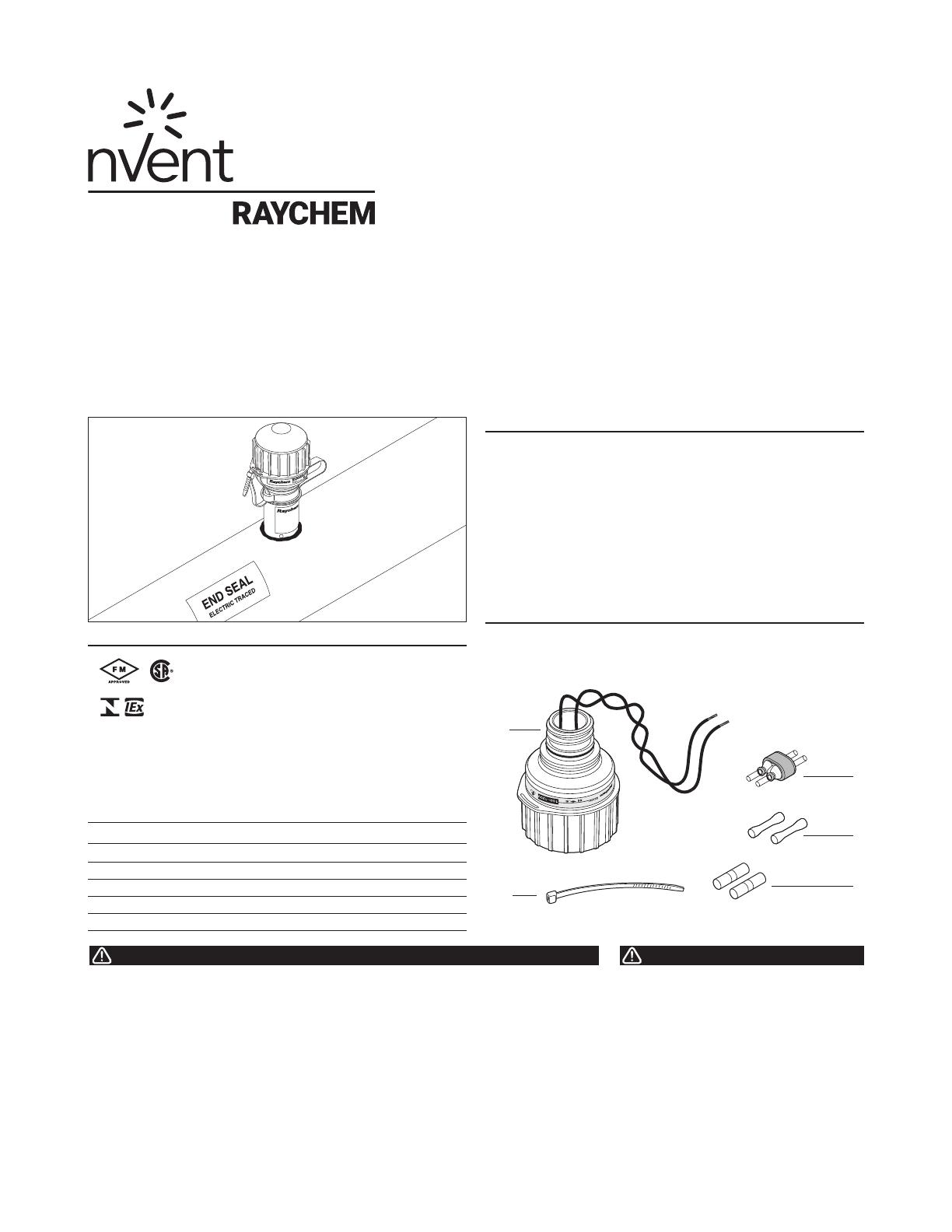
KIT CONTENTS
Item Qty Description
A 1 Light assembly
B 1 Core sealer (for BTV, QTVR, XTV, and KTV)
C 2 Insulated butt splices (red)
D 2 Insulated parallel crimps (blue)
E 1 Cable tie
A
E
APPROVALS
CLI, ZN1, AEx em II T*
(1)
Ex em II T*
Hazardous Locations
(1)
Except VPL
* For system Temperature Code, see heating cable or design documentation
.
(2)
Except KTV
Class I, Div. 2, Groups A, B, C, D
Class II, Div. 2, Groups E, F, G
Class III
E-100-LR is IECEx certified for use with:
BTV-CR/BTV-CT: IECEx BAS 06.0043X
QTVR-CT: IECEx BAS 06.0045X
XTV-CT: IECEx BAS 06.0044X
KTV-CT: IECEx BAS 06.0046X
VPL-CT: IECEx BAS 06.0048X
– WS
Ex em IIC T* Gb
(2)
IECEx
E-100-LR
Light Replacement And Retrofit Kit For High-Profile End Seal
Installation Instructions
This component is an electrical device that must be
installed correctly to ensure proper operation and to
prevent shock or fire. Read these important warnings and
carefully follow all of the installation instructions.
• To minimize the danger of fire from sustained electrical
arcing if the heating cable is damaged or improperly
installed, and to comply with the requirements of nVent,
agency certifications, and the National Electrical Code,
ground-fault equipment protection must be used. Arcing
may not be stopped by conventional circuit breakers.
• Component approvals and performance are based on the
use of nVent-specified parts only. Do not use substitute
parts or vinyl electrical tape.
• The black heating cable core and fibers are conductive
and can short. They must be properly insulated and
kept dry.
• Damaged bus wires can overheat or short. Do not break
bus wire strands when scoring the jacket or core.
• Keep components and heating cable ends dry before and
during installation.
• Bus wires will short if they contact each other. Keep bus
wires separated.
• Use only fire-resistant insulation materials, such as
fiberglass wrap or flame-retardant foam.
• Leave these installation instructions with the user for
future use.
HEALTH HAZARD: Prolonged or repeated contact with
the sealant in the core sealer may cause skin irritation.
Wash hands thoroughly. Overheating or burning the
sealant will produce fumes that may cause polymer fume
fever. Avoid contamination of cigarettes or tobacco.
Consult MSDS VEN0033 for further information.
CHEMTREC 24-hour emergency telephone:
(800) 424-9300.
Non-emergency health and safety information:
(800) 545-6258.


