Sanyo FMHX2462 Installation Instructions Manual
- Category
- Split-system air conditioners
- Type
- Installation Instructions Manual

– W-3WAY ECO-i System Air Conditioner –
R410A Models
for Refrigerant R410A
This air conditioner uses the new refrigerant R410A.
INSTALLATION INSTRUCTIONS
External diameter of service port R410A: 5/16"
NOTE
85464369236000 ©SANYO 2009
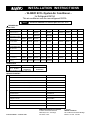
Indoor Units
Class 9 12 15 18 2419 36 5448
UM Slim Concealed-Duct UMHX0762 UMHX1262UMHX0962 UMHX1562 UMHX1862
XM
4-Way Air Discharge
Mini Semi-Concealed
XMHX1252 XMHX1852
U Concealed-Duct UHX0762 UHX1262UHX0962 UHX1562 UHX1862 UHX2462 UHX3662 UHX4862 UHX5462
X
4-Way Air Discharge
Semi-Concealed
XHX1252 XHX1852 XHX2452 XHX3652
A
1-Way Air Discharge
Semi-Concealed
AHX0752 AHX1252AHX0952
T Ceiling-Mounted THX1252 THX1852 THX2452
D
Concealed-Duct High
Static Pressure
DHX3652 DHX4852
FHX0762 FHX1262FHX0962 FHX1562 FHX1862 FHX2462F Floor-Standing
FMHX0762
FMHX1262
FMHX0962
FMHX1562
FMHX1862
FMHX2462
FM
Concealed-Floor
Standing
KHX0752 KHX1252KHX0952K Wall-Mounted KHX1862 KHX1962 KHX2452
Optional Controllers
Timer Wired Remote Controller RCS-TM80BG
Wireless Remote Controller (For X Type) RCS-SH80AAB.WL
Wireless Remote Controller (For XM Type) RCS-XM18AAB.WL
Wireless Remote Controller (For U, UM, D, F, FM Types) RCS-BH80AAB.WL
Wireless Remote Controller (For A, T Types) RCS-TRP80AAB.WL
RC
Wireless Remote Controller (For K Type) RCS-SH1AAB
Simplified Remote Controller RCS-KR1EG
System Controller SHA-KC64UG
Schedule Timer SHA-TM64AGB
Intelligent Controller SHA-KT256EA
Communication Adaptor SHA-KA128AAB
Remote Sensor ART-K45AGB
LonWorks Interface SHA-LN16UAB
SANYO North America Corporation
Commercial Solutions Division
2055 Sanyo Ave., San Diego
CA 92154, U.S.A.
In Canada
SANYO Canada Inc.
201 Creditview Road, Woodbridge
Ontario, L4L 9T1, Canada
7
Class 96
CHDZ09663
CHDZR09663
Outdoor Units
C
72
Eco-i W-3WAY
CHDZ07263
CHDZR07263
Refrigerant R410A is used in the outdoor units.

2
IMPORTANT!
Please Read Before Starting
This air conditioning system meets strict safety and oper-
ating standards. As the installer or service person, it is an
important part of your job to install or service the system so
it operates safely and efficiently.
For safe installation and trouble-free operation, you must:
●
Carefully read this instruction booklet before beginning.
●
Follow each installation or repair step exactly as shown.
●
Observe all local, state, and national electrical codes.
●
Pay close attention to all warning and caution notices
given in this manual.
This symbol refers to a hazard or
unsafe practice which can result
in severe personal injury or death.
This symbol refers to a hazard or
unsafe practice which can result
in personal injury or product or
property damage.
If Necessary, Get Help
These instructions are all you need for most installation
sites and maintenance conditions. If you require help for a
special problem, contact our sales/service outlet or your
certified dealer for additional instructions.
In Case of Improper Installation
The manufacturer shall in no way be responsible for
improper installation or maintenance service, including fail-
ure to follow the instructions in this document.
SPECIAL PRECAUTIONS
WARNING
When Wiring
ELECTRICAL SHOCK CAN CAUSE
SEVERE PERSONAL INJURY OR DEATH.
ONLY A QUALIFIED, EXPERIENCED
ELECTRICIAN SHOULD ATTEMPT TO
WIRE THIS SYSTEM.
• Do not supply power to the unit until all wiring and tubing
are completed or reconnected and checked.
• Highly dangerous electrical voltages are used in this
system. Carefully refer to the wiring diagram and these
instructions when wiring. Improper connections and inad-
equate grounding can cause accidental injury or death.
• Ground the unit following local electrical codes.
• Connect all wiring tightly. Loose wiring may cause over-
heating at connection points and a possible fire hazard.
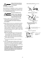
When Transporting
Be careful when picking up and moving the indoor and outdoor
units. Get a partner to help, and bend your knees when lifting
to reduce strain on your back. Sharp edges or thin aluminum
fins on the air conditioner can cut your fingers.
When Installing…
…In a Room
Properly insulate any tubing run inside a room to prevent
“sweating” that can cause dripping and water damage to
walls and floors.
…In Moist or Uneven Locations
Use a raised concrete pad or concrete blocks to provide
a solid, level foundation for the outdoor unit. This prevents
water damage and abnormal vibration.
…In an Area with High Winds
Securely anchor the outdoor unit down with bolts and a
metal frame. Provide a suitable air baffle.
…In a Snowy Area (for Heat Pump-type Systems)
Install the outdoor unit on a raised platform that is higher
than drifting snow. Provide snow vents.
When Connecting Refrigerant Tubing
• Ventilate the room well, in the event that is refrigerant
gas leaks during the installation. Be careful not to allow
contact of the refrigerant gas with a flame as this will
cause the generation of poisonous gas.
• Keep all tubing runs as short as possible.
• Use the flare method for connecting tubing.
• Apply refrigerant lubricant to the matching surfaces of
the flare and union tubes before connecting them, then
tighten the nut with a torque wrench for a leak-free con-
nection.
• Check carefully for leaks before starting the test run.
When Servicing
• Turn the power OFF at the main power box (mains)
before opening the unit to check or repair electrical parts
and wiring.
• Keep your fingers and clothing away from any moving
parts.
• Clean up the site after you finish, remembering to check
that no metal scraps or bits of wiring have been left
inside the unit being serviced.
• Ventilate any enclosed areas when installing or testing
the refrigeration system. Escaped refrigerant gas, on
contact with fire or heat, can produce dangerously toxic
gas.
• Confirm after installation that no refrigerant gas is leak-
ing. If the gas comes in contact with a burning stove, gas
water heater, electric room heater or other heat source,
it can cause the generation of poisonous gas.
WARNING
CAUTION
CAUTION

3
Check of Density Limit
The room in which the air conditioner is to be
installed requires a design that in the event of refrig-
erant gas leaking out, its density will not exceed a set
limit.
The refrigerant (R410A), which is used in the air condition-
er, is safe, without the toxicity or combustibility of ammonia,
and is not restricted by laws imposed to protect the ozone
layer. However, since it contains more than air, it poses the
risk of suffocation if its density should rise excessively. Suf-
focation from leakage of refrigerant is almost non-existent.
With the recent increase in the number of high density
buildings, however, the installation of multi air conditioner
systems is on the increase because of the need for effec-
tive use of floor space, individual control, energy conserva-
tion by curtailing heat and carrying power, etc.
Most importantly, the multi air conditioner system is able
to replenish a large amount of refrigerant compared to
conventional individual air conditioners. If a single unit of
the multi air conditioner system is to be installed in a
small room, select a suitable model and installation pro-
cedure so that if the refrigerant accidentally leaks out, its
density does not reach the limit (and in the event of an
emergency, measures can be made before injury can
occur).
ASHRAE and the International Mechanical Code of the
ICC as well as CSA provide guidance and define safe-
guards related to the use of refrigerants, all of which define
a Refrigerant Concentration Level (RCL) of 25 pounds
per 1,000 cubic feet for R410A refrigerant.
For additional guidance and precautions related to
refrigerant safety, please refer to the following documents:
International Mechanical Code 2009 (IMC-2009)
(or more recently revised)
ASHRAE 15
ASHRAE 34

4
New
tool?
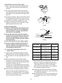
1-2. Prevent impurities including water, dust and oxide from entering the tubing. Impurities can cause R410A refriger-
ant deterioration and compressor defects. Due to the features of the refrigerant and refrigerating machine oil, the
prevention of water and other impurities becomes more important than ever.
2. Be sure to recharge the refrigerant only in liquid form.
2-1. Since R410A is a non-azeotrope, recharging the refrigerant in gas form can lower performance and cause defects
in the unit.
2-2. Since refrigerant composition changes and performance decreases when gas leaks, collect the remaining refriger-
ant and recharge the required total amount of new refrigerant after fixing the leak.
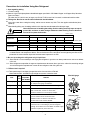
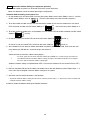
3. Different tools required
3-1. Tool specifications have been changed due to the characteristics of R410A.
Some tools for R22- and R407C-type refrigerant systems cannot be used.
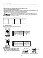
Precautions for Installation Using New Refrigerant
1. Care regarding tubing
1-1. Process tubing
●
Material: Use C1220 phosphorous deoxidized copper specified in JIS H3300 “Copper and Copper Alloy Seamless
Pipes and Tubes.”
For tubes of ø7/8" (ø22.22 mm) or larger, use C1220 T-1/2H material or H material, and do not bend the tubes.
●
Tubing size: Be sure to use the sizes indicated in the table below.
●
Use a tube cutter when cutting the tubing, and be sure to remove any flash. This also applies to distribution joints
(optional).
●
When bending tubing, use a bending radius that is 4 times the outer diameter of the tubing or larger.
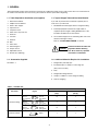
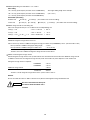
* Using tools for R22 and R407C and new tools for R410A together can cause defects.
Manifold gauge
Vacuum pump
Outlet
Inlet
CAUTION
Use sufficient care in handling the tubing. Seal the tubing ends with caps or tape to
prevent dirt, moisture, or other foreign substances from entering. These substances
can result in system malfunction.
R407C tools
Item compatible Remarks
with R410A?
Manifold gauge Yes No Types of refrigerant, refrigerating machine
oil, and pressure gauge are different.
Charge hose Yes No To resist higher pressure, material must be changed.
Vacuum pump Yes Yes Use a conventional vacuum pump if it is equipped
with a check valve. If it has no check valve,
purchase and attach a vacuum pump adapter.
Leak detector Yes No Leak detectors for CFC and HCFC that
react to chlorine do not function because
R410A contains no chlorine. Leak detector
for HFC134a can be used for R410A.
Flaring oil Yes No For systems that use R22, apply mineral oil (Suniso oil)
to the flare nuts on the tubing to prevent refrigerant
leakage. For machines that use R407C or R410A, apply
synthetic oil (ether oil) to the flare nuts.
Material O
Copper tube
Outer diameter 1/4 (6.35) 3/8 (9.52) 1/2 (12.7) 5/8 (15.88) 3/4 (19.05)
Wall thickness 1/32 (0.8) 1/32 (0.8) 1/32 (0.8) 5/128 (1.0)
over 5/128 (1.0)
Material 1/ 2 H, H
Copper tube
Outer diameter 7/8 (22.22) 1 (25.4) 1-1/8 (28.58) 1-1/4 (31.75) 1-1/2 (38.1) 1-5/8 (41.28)
Wall thickness 5/128 (1.0) 5/128 (1.0) 5/128 (1.0) 3/64 (1.1)
over 3/64 (1.15)
over
3/64 (1.20)
Unit: in. (mm)
Unit: in. (mm)

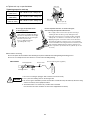
5
Valve
Liquid
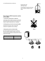
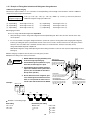
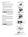
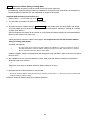
3-2. Use R410A exclusive cylinder only.
Single-outlet valve
(with siphon tube)
Liquid refrigerant should be recharged
with the cylinder standing on end as
shown.
New refrigerant R410A cannot be used for
earlier models
1. Compressor specifications are different.
If recharging a R22 or R407C compressor with R410A,
durability will significantly decrease since some of the
materials used for compressor parts are different.
2. Existing tubing cannot be used (especially R22).
Completely cleaning out residual refrigerating
machine oil is impossible, even by flushing.
3. Refrigerating machine oil differs (R22).
Since R22 refrigerating machine oil is mineral oil, it
does not dissolve in R410A. Therefore, refrigerating
machine oil discharged from the compressor can cause
compressor damage.
R22 refrigerating machine oil Mineral oil (Suniso oil)
R407C refrigerating machine oil Synthetic fluid (ether oil)
R410A refrigerating machine oil Synthetic fluid (ether oil)
R410A

6
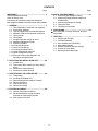
CONTENTS
Page Page
IMPORTANT! ............................................................... 2
Please Read Before Starting
Check of Density Limit
Precautions for Installation Using New Refrigerant
New refrigerant R410A cannot be used for earlier models
1. GENERAL ............................................................... 7
1-1. Tools Required for Installation (not supplied)
1-2. Accessories Supplied
1-3. Type of Copper Tube and Insulation Material
1-4. Additional Materials Required for Installation
1-5. Tubing Length
1-6. Tubing Size
1-7. Straight Equivalent Length of Joints
1-8. Additional Refrigerant Charge
1-9. System Limitations
1-10. Installation Standards
1-11. Check of Limit Density
1-12. Installing Distribution Joint
1-13. Optional Distribution Joint Kits
1-14. Optional Solenoid Valve Kit
1-15. Example of Tubing Size Selection and
Refrigerant Charge Amount
2. SELECTING THE INSTALLATION SITE .............. 20
2-1. Outdoor Unit
2-2. Precautions When Installing in Heavy Snow
Areas
2-3. Dimensions of Wind Ducting
2-4. Dimensions of Snow Ducting
3. HOW TO INSTALL THE OUTDOOR UNIT ............... 24
3-1. Transporting
3-2. Installing the Outdoor Unit
3-3. Remove the Brackets Used for Transport
3-4. Routing the Tubing
3-5. Prepare the Tubing
3-6. Connect the Tubing
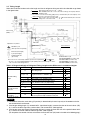
4. ELECTRICAL WIRING .......................................... 28
4-1. General Precautions on Wiring
4-2. Recommended Wire Length and Wire
Diameter for Power Supply System
4-3. Wiring System Diagram
5.HOW TO PROCESS TUBING ................................. 32
5-1. Connecting the Refrigerant Tubing
5-2. Connecting Tubing Between Indoor and
Outdoor Units
5-3. Insulating the Refrigerant Tubing
5-4. Taping the Tubes
5-5. Finishing the Installation
6. AIR PURGING ...................................................... 36
■
Air Purging with a Vacuum Pump (for Test Run)
Preparation
7. TEST RUN............................................................. 39
7-1. Preparing for Test Run
7-2. Test Run Procedure
7-3. Main Outdoor Unit PCB Setting
7-4. Auto Address Setting
7-5. Remote Controller Test Run Settings
7-6. Caution for Pump Down
7-7. Meaning of Alarm Messages

7
1-2. Accessories Supplied
See Table 1-1.
1-1. Tools Required for Installation (not supplied)
1. Flathead screwdriver
2. Phillips head screwdriver
3. Knife or wire stripper
4. Tape measure
5. Carpenter’s level
6. Sabre saw or key hole saw
7. Hacksaw
8. Core bits
9. Hammer
10. Drill
11. Tube cutter
12. Tube flaring tool
13. Torque wrench
14. Adjustable wrench
15. Reamer (for deburring)
1-3. Type of Copper Tube and Insulation Material
If you wish to purchase these materials separately from a
local source, you will need:
1. Deoxidized annealed copper tube for refrigerant tubing.
2. Foamed polyethylene insulation for copper tubes as
required to precise length of tubing. Wall thickness of the
insulation should be not less than 5/16 in.
3. Use insulated copper wire for field wiring. Wire size varies
with the total length of wiring.
Refer to
“
4. ELECTRICAL WIRING” for details.
1-4. Additional Materials Required for Installation
1. Refrigeration (armored) tape
2. Insulated staples or clamps for connecting wire
(See your local codes.)
3. Putty
4. Refrigeration tubing lubricant
5. Clamps or saddles to secure refrigerant tubing
6. Scale for weighing
CAUTION
Check local electrical codes and
regulations before obtaining
wire. Also, check any specified
instructions or limitations.
1. GENERAL
This booklet briefly outlines where and how to install the air conditioning system. Please read over the entire set of instructions for
the outdoor unit and make sure all accessory parts listed are with the system before beginning.
Table 1-1 Outdoor Unit
Figure
Q’ty
0
1
0
1
1
1
1
(hp = horse power)
07263 Model
(8 hp)
09663 Model
(10 hp)
1
Instruction manual paper
Connection tubing
Part name
Outer
diameter
Outer
diameter
Inner
diameter
o3/4"(o19.05)
Inner
diameter
o1-1/8"(o28.58)
o7/8"(o22.22)
Outer
diameter
o3/4"(o19.05)
o3/4"(o19.05)
Inner
diameter
o5/8"(o15.88)

8
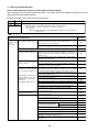
1-5. Tubing Length
Item Mark Contents Length (ft.)
L1 Max. tubing length
Actual length 492
Equivalent length 574
$L (L2 – L4)
Difference between max. length and min.
131
length from the No. 1 distribution joint
LM Max. length of main tubing (at max. diameter) 262
1
1
2
,
2
...
...
Max. length of each distribution tube 98
L1+
+
+
Total max. tubing length including length of
984
A
+
B
+LF+LG+LH each distribution tube (only liquid tubing)
L5
L3
Distance between outdoor units
H1
When outdoor unit is installed higher than indoor unit 164
When outdoor unit is installed lower than indoor unit 131
H2 Max. difference between indoor units
H3 Max. difference between outdoor units
L = Length, H = Height
Allowable tubing
length
Allowable elevation
difference
32
49
13
*2
6.6
Allowable length of
joint tubing
T-joint tubing (field-supply); Max. tubing length between
the first T-joint and solidly welded-shut end point
40
40
Balance tubing
(ø
3/8"
)
For
extension
Max. 1.3 ft
For
extension
Max. 1.3 ft
T-joint tubing
(header joint system)
Solenoid valve kit
Explanation of symbols
Distribution joint
(APR: purchased separately)
Ball valve (field supply)
T-joint (field supply)
Solidly welded shut
(pinch weld)
Note: Do not use commercially available T-joints for the liquid tubing
and parts.
* Be sure to use special R410A distribution joints (APR: purchased separately) for outdoor
unit connections and tubing branches.
1. Main tubing length LM = LA + LB … b 262 ft
2. Main distribution tubes LC – LH are selected according to the capacity after the
distribution joint.
3. The outdoor connection main tubing (LO portion) is determined by the total capacity of the
outdoor units that are connected to the tube ends.
4. Sizes of indoor unit connection tubing
1 – 40 are determined by the connection
tubing sizes on the indoor units.
R410A distribution joint
APR-CHRZP900BAB (for outdoor unit)
APR-RZP224BAB (for indoor unit)
APR-RZP680BAB (for indoor unit)
APR-RZP1350BAB (for indoor unit)
Select the installation location so that the length and size of refrigerant tubing are within the allowable range shown
in the figure below.
1:
2:
3:
The outdoor connection main tubing (LO portion) is determined by the total capacity of the outdoor units that
are connected to the tube ends.
If the longest tubing length (L1) exceeds 295 ft. (equivalent length), increase the sizes of the main tubes (LM)
by 1 rank for the discharge tubes, suction tubes, and narrow tubes. (field supplied)
If the longest main tube length (LM) exceeds 164 feet, increase the main tube size at the portion before 164 ft.
by 1 rank for the suction tubes and discharge tubes. (field supplied)
(For the portion that exceeds 164 feet, set based on the main tube sizes (LA) listed in the table on the following page.)
NOTE
Table 1-2 Ranges that Apply to Refrigerant Tubing Lengths and to Differences in Installation Heights

9
*1: If future extension is planned, select the tubing diameter based on the total horsepower after extension.
However extension is not possible if the resulting tubing size is two ranks higher.
*2: The balance tube (outdoor unit tube) diameter is ø3/8" (ø9.52).
*3: Type 1 tubing should be used for the refrigerant tubes.
*4: If the length of the longest tube (L1) exceeds 295 ft. (equivalent length), increase the main tube (LM) size by 1 rank for the
suction, discharge, and liquid tubes. (Use field-supply reducers.) (Select from Table 1-3 and Table 1-9.)
*5: If the longest main tube length (LM) exceeds 164 ft., increase the main tube size at the portion before 164 ft. by 1 rank for
the suction tubes and discharge tubes.
(For the portion that exceeds 164 ft., set based on the main tube sizes (LA) listed in the table above.)
■
Size of tubing (LO) between outdoor units
Select the size of tubing between outdoor units based on the main tubing size (LA) as given in the table above.
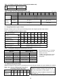
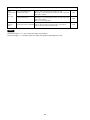
Table 1-4 Main Tubing Size After Distribution (LB, LC...)
*1: The outdoor unit connection tubing (LO) is
determined by the total capacity of the outdoor
units connected to the tube ends. The tubing
size is selected based on the table of main
tube sizes after the branch.
*2: If the total capacity of the indoor units con-
nected to the tube ends is different from the
total capacity of the outdoor units, then the
main tube size is selected based on the total
capacity of the outdoor units.
(For LA, LB, and LF in particular)
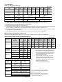
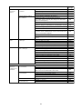
1-6. Tubing Size
Table 1-3 Main Tubing Size (LA)
24
192,000
(56.2)
20
o7/8"
(o22.22)
8
72,000
(21.1)
o1/2"
(o12.7)
96,000
(28.1)
10
8
8
10
10
8
8
8
144,000
(42.2)
16
10
8
168,000
(49.2)
18
o3/8"
(o9.52)
216,000
(63.3)
28
240,000
(70.3)
26
10
8
8
10
10
8
264,000
(77.3)
30
10
10
10
288,000
(84.3)
108
BTU/h
(kW)
Total system horsepower
Combined outdoor units
Suction tubing
Discharge tubing
Liquid tubing
(o19.05)
o3/4"
o1-1/8"
(o28.58)
o7/8"
(o22.22)
(o15.88)
o5/8"
o1-3/8"
(o34.92)
o1-1/8"
(o28.58)
o3/4"
(o19.05)
(o15.88)
o5/8"
Unit: in. (mm)
ø3/4"
(ø19.05)
ø1-1/8"
(ø28.58)
ø1-3/8"
(ø34.92)
ø5/8"
(ø15.88)
ø1-1/8"
(ø28.58)
ø1/2"
(ø12.70)
ø1-1/8"
(ø28.58)
ø3/8"
(ø9.52)
ø7/8"
(ø22.22)
ø5/8"
(ø15.88)
ø5/8"
(ø15.88)
ø3/4"
(ø19.05)
ø5/8"
(ø15.88)
ø3/4"
(ø19.05)
ø3/4"
(ø19.05)
ø7/8"
(ø22.22)
ø3/8"
(ø9.52)
ø3/8"
(ø9.52)
ø3/8"
(ø9.52)
ø1/2"
(ø12.70)
–
238.900
(25 hp)
200.600
(21 hp)
24.200
(2.5 hp)
24.200
(2.5 hp)
334.400
(35 hp)
85.300
(9 hp)
54.600
(6 hp)
54.600
(6 hp)
85.300
(9 hp)
258.000
(27 hp)
ø3/4"
(ø19.05)
ø1-1/8"
(ø28.58)
ø1-1/2"
(ø38.10)
–
334.400
(35 hp)
ø3/4"
(ø19.05)
ø1-1/8"
(ø28.58)
258.000
(27 hp)
238.900
(25 hp)
102.400
(11 hp)
ø1/2"
(ø12.70)
ø1-1/8"
(ø28.58)
ø3/4"
(ø19.05)
102.400
(11 hp)
124.200
(13 hp)
124.200
(13 hp)
Below BTU/h
Over BTU/h
143.300
(15 hp)
ø1/2"
(ø12.70)
ø1-1/8"
(ø28.58)
ø7/8"
(ø22.22)
ø7/8"
(ø22.22)
ø1-1/8"
(ø28.58)
143.300
(15 hp)
162.400
(17 hp)
ø5/8"
(ø15.88)
ø1-1/8"
(ø28.58)
162.400
(17 hp)
200.600
(21 hp)
Total capacity
after distribution
Tubing size
Suction tubing
Liquid tubing
Discharge tubing
hp = horsepower
Unit: in. (mm)
Below BTU/h
Over BTU/h
Total capacity
after distribution
Tubing size
ø1-3/8"
(ø34.92)
Suction tubing
Liquid tubing
Discharge tubing
Table 1-5 Outdoor Unit Tubing Connection Size ( A – D)
o3/8" (o9.52)
o3/8" (o9.52)
72,000
(21.1)
96,000
(28.1)
Flare connection
Brazing connection
Brazing connection
o3/8" (o9.52)
Flare connection
Balance tubing
Liquid tubing
Discharge
tubing
Suction tubing
BTU/h
(kW)
Unit: in. (mm)
*1 If the size of tubing (LA) is less than 16.4 feet,
it is recommended that the tubing diameter be
larger than
Ø7/8" (Ø22.22).
*2 If the size of tubing (LA) is less than 16.4 feet,
it is recommended that the tubing diameter be
larger than Ø1-1/8" (Ø28.58).
o5/8"
(o15.88)
o3/4"
(o19.05)
o3/4"
*
1
(o19.05)
*
1
o7/8"
*
2
(o22.22)
*
2

10
1-7. Straight Equivalent Length of Joints
Design the tubing system by referring to the following table for the straight equivalent length of joints.
Table 1-8 Straight Equivalent Length of Joints
Table 1-9 Refrigerant tubing (Existing tubing can be used.)
Tubing size (in. (mm))
Material O Material 1/2H • H
ø1/4" (ø6.35) t1/32 (t0.8)
ø3/8" (ø9.52) t1/32 (t0.8) ø1-1/8" (ø28.58) t5/128 (t1.0)
ø1/2" (ø12.7) t1/32 (t0.8) ø1-1/4" (ø31.75) t3/64 (t1.1)
ø5/8" (ø15.88) t5/128 (t1.0) ø1-1/2" (ø38.10) over t3/64 (t1.15)
ø3/4" (ø19.05)
over t5/128 (t1.0)
ø1-5/8" (ø41.28) over t3/64 (t1.20)
ø7/8" (ø22.22) t5/128 (t1.0)
* When bending the tubes, use a bending
radius that is at least 4 times the outer
diameter of the tubes.
In addition, take sufficient care to avoid
crushing or damaging the tubes when
bending them.
1-8. Additional Refrigerant Charge
Additional refrigerant charge amount is calculated from the liquid tubing total length and a type of outdoor unit as follows.
Required amount of additional refrigerant charge =
[ (Amount of additional refrigerant charge per ft. of
each size of liquid tube × its tube length) + (...) + (...)]
+ [(Necessary amount of additional refrigerant charge
per outdoor unit + (...) + (...)]
* Always charge accurately using a scale for weighing.
*1: For the solenoid valve kits, use type 160 with parallel specifications. Branch the tubing before and after the solenoid valve kits.
Table 1-7 Indoor Unit Tubing Connection Size ( 1 – 40)
Unit: in. (mm)
Distribution
joint-solenoid
valve kit tubing
Solenoid valve
kit-Indoor
unit tubing
connection
Discharge tubing
Liquid tubing
Suction tubing
Indoor unit type
Total system horsepower
7 9 12 15 18 19 24 36 48 54
0.8 1 1.3 1.7 2 2.1 3 4 5 5.5
o5/8" (o15.88)
o1/2" (o12.7)
o3/8" (o9.52)
Gas tubing
Liquid tubing
o1/2" (o12.7)
o1/4" (o6.35)
o5/8" (o15.88)
o3/8" (o9.52)
Gas tubing size (in.(mm))
1/2"
(12.7)
5/8"
(15.88)
3/4"
(19.05)
7/8"
(22.22)
1"
(25.4)
1-1/8"
(28.58)
1-1/4"
(31.8)
1-1/2"
(38.1)
90 o elbow
1 ft.
(0.30 m)
1.1 ft.
(0.35 m)
1.4 ft.
(0.42 m)
1.6 ft.
(0.48 m)
1.7 ft.
(0.52 m)
1.9 ft.
(0.57 m)
2.3 ft.
(0.70m)
2.6 ft.
(0.79 m)
45 o elbow
0.8 ft.
(0.23 m)
0.9 ft.
(0.26 m)
1 ft.
(0.32 m)
1.2 ft.
(0.36 m)
1.3 ft.
(0.39 m)
1.4 ft.
(0.43 m)
1.7 ft.
(0.53 m)
1.9 ft.
(0.59 m)
U-shape tube bent
(R2–23/64–3–15/16 in.)
3 ft.
(0.90 m)
3.4 ft.
(1.05 m)
4.1 ft.
(1.26 m)
4.7 ft.
(1.44 m)
5.1 ft.
(1.56 m)
5.6 ft.
(1.71 m)
6.9 ft.
(2.10 m)
7.8 ft.
(2.37 m)
T r ap bend
7.5 ft.
(2.30 m)
9.2 ft.
(2.80 m)
10.5 ft.
(3.20 m)
12.5 ft.
(3.80 m)
14.1 ft.
(4.30 m)
15.4 ft.
(4.70 m)
16.4 ft.
(5.00 m)
14.0 ft.
(5.80 m)
Y -br anch distr ib ution joint Equiv alent length con v ersion not needed.
Ball v alv e f or ser vice Equiv alent length con v ersion not needed.
Table 1-10-1 Amount of Refrigerant Charge Per ft.,
According to Liquid Tubing Size
Liquid tubing
size
ø1/4"
(ø6.35)
ø3/8"
(ø9.52)
ø1/2"
(ø12.7)
ø5/8"
(ø15.88)
ø3/4"
(ø19.05)
ø7/8"
(ø22.22)
Amount of
refrigerant
charge (oz/ft.)
0.279 0.602 1.38 1.99 2.78 3.93
Table 1-6 Refrigerant Charge Amount at Shipment (for outdoor unit)
DC
CHDZ07263 CHDZ09663
CHDZR07263 CHDZR09663
(oz)
416 416

11
Common solenoid valve kit
●
Multiple indoor units under group control can utilize a solenoid valve kit in common.
●
Categories of connected indoor unit capacities are determined by the solenoid valve kit.
1-9. System Limitations
Table 1-11 System Limitations
Max. No. allowable connected outdoor units 3
Max. capacity allowable connected outdoor units
288,000 BTU/h (30 hp, 84.3 kw)
Max. connectable indoor units 40
*1
Max. allowable indoor/outdoor capacity ratio 50 – 130 %
Type of solenoid valve kit Total capacity of indoor units (BTU/h)
160 19.000
<
Total capacity
<
54.600
56 7.500
<
Total capacity
<
19.000
*1: In the case of 20 hp (type 191.100 BTU/h) or smaller units, the number is limited by the total capacity of the connected indoor units.
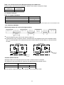
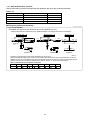
1-10. Installation Standards
Relationship between A/C units and refrigerant tubing
Outdoor unit Outdoor unit Indoor unit
Suction tube
Discharge tube
Liquid tube
Balance tube
Suction tube
Discharge tube
Liquid tube
Gas tube
Liquid
tube
4-tube layout 3-tube layout 2-tube layout
Solenoid
valve kit
Indoor unit
Room
Hallway
Indoor unit
Room
Indoor unit
Room
Hallway
Indoor unit
Room
Solenoid
valve kit
Solenoid
valve kit
●
Install the solenoid valve kit 98 ft. or less from the indoor unit.
●
In quiet locations such as hospitals, libraries, and hotel rooms, the refrigerant noise may be somewhat notice-
able. It is recommended that the solenoid valve kit be installed inside the corridor ceiling, at a location outside
the room.
Desirable
●
If the capacity range is exceeded, use 2 solenoid valves connected in parallel.
Undesirable
Table 1-10-2 Necessary Amount of Refrigerant Charge Per Outdoor Unit
Further charge a certain amount listed below in addition to the amount of refrigerant charge.
CHDZ07263
CHDZR07263
CHDZ09663
CHDZR09663
42 oz/unit 42 oz/unit

12
WARNING
Always check the gas density
limit for the room in which the
unit is installed.
1-11. Check of Limit Density
When installing an air conditioner in a room, it is necessary
to ensure that even if the refrigerant gas accidentally leaks
out, its density does not exceed the limit level for that room.
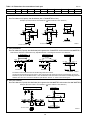
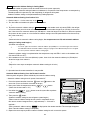
1-12. Installing Distribution Joint
15 to 30
B
A
B
A
Tube branching methods (horizontal use)
Arrow view
Horizontal
line
View as seen
from arrow
Ball valve
(BV: purchased
separately)
Main tubing
Types of vertical trap specifications
(If only 1 unit is connected, a ball valve
is also needed on this side.)
Indoor unit (1)
(When not using ball valve)
(When using ball valve)
Branch tubing is
directed upward.
(Each unit is connected
to tubing that is either
level or is directed
downward.)
Main tubing
Indoor unit
More than
7–7/8"
Indoor unit (more than 2 units)
Horizontal
Indoor unit is directed downward
CAUTION
Pay special attention to any
location, such as a basement,
etc., where leaking refrigerant
can accumulate, since refrig-
erant gas is heavier than air.
Outdoor
Indoor
Indoor
Indoor
Solidly welded
shut (X)
Horizontal
line
Horizontal
line
L3 6.56 ft.
Install at a
positive angle
Install at a
positive angle
(15 – 30°)
Header joint system (Indoor)
(1) Refer to “HOW TO ATTACH DISTRIBUTION JOINT”
enclosed with the optional distribution joint kit
(APR-CHRZP900BAB, RZP224BAB, RZP680BAB,
RZP1350BAB).
(2) When creating a branch using a commercially available
T-joint (header joint system), orient the main tubing so
that it is either horizontal (level) or vertical. In order to
prevent accumulation of refrigerant oil in stopped units,
if the main tubing is horizontal then each branch tubing
length should be at an angle that is greater than horizon-
tal. If the main tubing is vertical, provide a raised starting
portion for each branch.
[Header joint system]
●
Be sure to solidly weld shut the T-joint end (marked
by “X” in the figure). In addition, pay attention to the
insertion depth of each connected tube so that the
flow of refrigerant within the T-joint is not impeded.
●
When using the header joint system, do not make fur-
ther branches in the tubing.
●
Do not use the header joint system on the outdoor
unit side.
(3) If there are height differences between indoor units or if
branch tubing that follows a distribution joint is connect-
ed to only 1 unit, a trap or ball valve must be added to
that distribution joint. (When adding the ball valve, locate
it within 15 - 3/4" of the distribution joint.)
If a trap or ball valve is not added, do not operate the
system before repairs to a malfunctioning unit are
completed. (The refrigerant oil sent through the tub-
ing to the malfunctioning unit will accumulate and
may damage the compressor.)

13
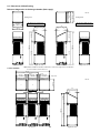
1-13. Optional Distribution Joint Kits
See the installation instructions packaged with the distribution joint kit for the installation procedure.
Table 1-12
1. APR-CHRZP900BAB
For outdoor unit (Capacity after distribution joint is 307.100 BTU/h or less.)
11-13/16 11-13/16
13-25/64
D
C
B
EDF
3/41-1/8 3/85/8 1/21
Size
7/81-1/4
Part B Part C Part D Part E Part F Part G Part H Part I
Inch
InsulationInsulation
Joint
Distribution
Insulation
C
C
H
I
HI
E
G
F
E
EFG
E
F
G
#C
C
E
D
DE
#C
D
#C
E
F
#C
Suction Tube
Discharge Tube
Liquid Tube
Unit: in.
*Insulators for both the Suction tube and the Discharge tube are the same.
*Suction tube and Discharge tube are similar in sizes and both the tube entrances have the same diameter. So the both
Distribution joints can fit into different tubes. Since the diameter of the tube ends for both Suction and Discharge tube are
different, take care not to connect the distribution joint different. See the " # " marks on the above figures.
Note that the dimension marked with every alphabetical letter in the diagram shows the inner diameter.
Table 1-13 Dimensions for connections of each part
Model name Cooling capacity after distribution Remarks
1. APR-CHRZP900BAB 307.100 BTU/h or less For outdoor unit
2. APR-RZP224BAB 76.400 BTU/h or less For indoor unit
3. APR-RZP680BAB 232.000 BTU/h or less For indoor unit
4. APR-RZP1350BAB 460.700 BTU/h or less For indoor unit
■
Tubing size (with thermal insulation)

14
2. APR-RZP224BAB
Use: For indoor unit (Capacity after distribution joint is 76.400 BTU/h or less.)
3. APR-RZP680BAB
Use: For indoor unit (Capacity after distribution joint is greater than 76.400 BTU/h and no more than 232.000 BTU/h.)
4. APR-RZP1350BAB
Use: For indoor unit (Capacity after distribution joint is greater than 232.000 BTU/h and no more than 460.700 BTU/h.)
Example: (F below indicates inner diameter. below indicates outer diameter.)
Thermal insulation
Thermal insulation
Thermal insulation
Suction tubing
Discharge tubing
Liquid tubing
G
GH
F
F
H
G
G
G
G
F
H
HH
HIIH
H
I
F
F
F
H
H
H
8–17/64
2–11/64
3–5/8 15/32
5–45/64
2–11/64
1–37/64
3–1/32 9/32
7–21/64
5–23/64
2–23/32
9–1/4
F
HG
G
Insulation
Insulation
Insulation
*Insulators for both the Suction tube and the Discharge tube are the same.
*Suction tube and Discharge tube are similar in sizes and both the tube entrances have the same diameter. So the both
Distribution joints can fit into different tubes. Since the diameter of the tube ends for both Suction and Discharge tube are
different, take care not to connect the distribution joint different. See the " # " marks on the above figures.
Note that the dimension marked with every alphabetical letter in the diagram shows the inner diameter.
I
H
IH
I
H
EFD
D
C
C
#C
#D
#D
#C
EF
GF E
EFG
E
F
G
E
F
D
E
F
FED
FE
H
G
G
Suction Tube
Discharge Tube
Liquid Tube
11-13/16
13-25/64
11-13/16
Position A B C D E F G H I J
Dimension ø1-1/2" ø1-1/4" ø1-1/8" ø1" ø7/8" ø3/4" ø5/8" ø1/2" ø3/8" –
Example: (B below indicates inner diameter. below indicates outer diameter.)
Thermal insulation
Thermal insulation
Suction tubing • Discharge tubing
Liquid tubing
B
G
F
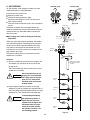
E
E
F
G
E
F
G
HI
H
I
I
H
B
BB
ECDAFFADCE
A
C
D
E
F
H
G
5–1/8
13–25/64
G
G
G
1–31/32
C
BBC
B
C
F
3–35/64
4–9/64 4–13/32
1–49/64
2–11/64
Table 1-14 Dimensions for connections of each part
Unit: in.
Unit: in.
Unit: in.
Unit: in.

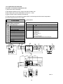
15
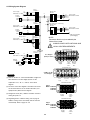
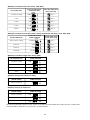
Part
Number
Cover of relay kit
14
Relay kit
13
Cover of control box
12
Earth (M5 with washer)
11
Terminal for communication line
10
Terminal for power line
9
Base of control box
8
Service panel
7
Discharge tube: ID1/2"
6
Suction tube: ID5/8"
5
Liquid tube : ID3/8"
4
Suspension hook
3
Liquid tube : ID1/4"
2
Types and specifications of
tubing connections
1
ATK-RZP56BAWB
Gas tube: ID1/2"
Specifications
12
1
2
6
4
5
10
1314
5-25/32
9-13/32
5-55/64
53/64 2-63/64
9-29/64
63/64
63/64
2-31/64
3-15/16
6-29/64
8-15/32
2-31/64
3-15/16
5-55/64
7/16
1-7/64
43/64
4-21/64 4-21/64
5-3/64
4-1/4
3-25/32
2-3/64
5-9/32
4-49/64
5-55/64
1-21/32
4-7/32
1-21/32
3-21/32
3-21/32
Unit: in.
3
7
9
11
8
ATK-RZP56BAWB
Compatibility
Power source
Power input
Net weight
Accessories
7.500 Total capacity of indoor units (BTU/h) < 19.000
Single-phase AC 208–230V 60Hz (supplied by indoor unit)
33 W max.
151.7 oz.
Washer x 2
Hanging hook
M4 screw x 4
Tapping screw x 4
Wire holder
3-WAY connect wire
ACC-3WAY-AAB (Solenoid Valve Relay Kit)
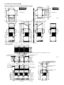
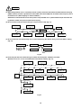
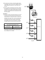
1-14. Optional Solenoid Valve Kit
Precautions on Installation of Solenoid Valve Kit
(1) Clean base metals thoroughly.
(2) Use proper ventilation to carry fumes away from the work area.
(3) Use a high quality silver based solder of at least 15 % silver.
(4) Heat the base materials broadly and uniformly.
(5) Take precautions not to overheat the device which could damage sensitive internal components.
(6) Insure compliance with all local codes!

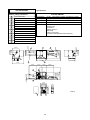
16
Part
Number
Cover of relay kit
14
Relay kit
13
Cover of control box
12
Earth (M5 with washer)
11
Terminal for communication line
10
Terminal for power line
9
Base of control box
8
Service panel
7
Discharge tube: ID1/2"
6
Suction tube: ID5/8"
5
Liquid tube : ID3/8"
4
Suspension hook
3
Liquid tube : ID3/8"
2
Types and specifications of
tubing connections
ATK-RZP160BAWB
Compatibility
Power source
Power input
Net weight
Accessories
1
ATK-RZP160BAWB
19.000 Total capacity of indoor units (BTU/h) < 54.600
Single-phase AC 208–230V 60Hz (supplied by indoor unit)
40 W max.
165.8 oz.
Gas tube: ID5/8"
Specifications
9
11
10
8
12
1
3
2
6
4
5
10
1314
5-25/32
5-55/64 5-55/64
43/64
4-49/64
5-9/32
2-3/64
5-3/64
3-25/32
4-1/4
1-7/64
7/16
5-55/64
9-29/64
4-21/64 4-21/64
1-21/32
63/64
63/64
2-31/64
3-15/16
2-31/64
3-15/16
6-29/64
8-15/32
3-21/32
4-7/32
1-21/32
3-21/32
9-13/32
53/64 2-63/64
7
Unit: in.
Washer x 2
Hanging hook
M4 screw x 4
Tapping screw x 4
Wire holder
3-WAY connect wire
ACC-3WAY-AAB (Solenoid Valve Relay Kit)

17
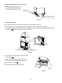
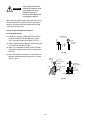
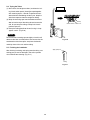
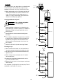
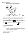
Suspension bolt (3/8" or M10) (field supplied)
Nut (field supplied) (3/8" or M10)
Washer
M4 screws
(12 pcs.)
Suspension hook
Notes on Installation
• Be sure to secure the valve body by using its structure with the suspension bolt, etc.
• Install the valve body within a distance of 98 ft. from the indoor unit.
Some refrigerant noise will be produced. Therefore in hospitals, libraries, hotel guest rooms, and other quiet
locations, it is recommended that the solenoid valve kit be installed on the ceiling reverse side of a hallway or
another location separated from the room.
• When installing the valve body, install with the top surface facing up. Secure 7-7/8" or more of space to the front
so that the front service panel can be removed.
• If the supplied suspension hook will not be used, and other fastening devices will be attached in the field, use
the 4 screw holes on the top surface. DO NOT use any long screws other than the supplied screws. Use of other
screws may puncture the internal tubing, resulting in refrigerant leakage.
• Do not block the air holes.
NOTE
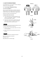
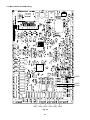
Installation of Solenoid Valve Kit
1. Install the relay kit into the indoor unit.
Refer to the Installation Manual for the solenoid valve kit.
2. Connect the solenoid valve kit and the relay kit in the field.
Relay kit
Front
Cover of control box
Suction tube
Discharge tube
Top surface
Suspension hook
Gas tube
Liquid tube
Liquid tube
Connect with
conduit for
power supply
Front
7-7/8" or more
Service space

18
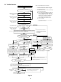
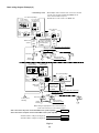
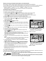
1-15. Example of Tubing Size Selection and Refrigerant Charge Amount
Additional refrigerant charging
Based on the values in Tables 1-3, 4, 5, 9 and 10-2 use the liquid tubing size and length, and calculate the amount of additional
refrigerant charge using the formula below.
Required additional
refrigerant charge (oz)
=
3.93
×
(a) + 2.78
×
(b) + 1.99
×
(c) + 1.38
×
(d) + 0.602
×
(e) + 0.279
×
(f) + Necessary amount of
additional refrigerant charge per outdoor unit
(a) : Liquid tubing Total length of ø7/8" (ft.) (d) : Liquid tubing Total length of ø1/2" (ft.)
(b) : Liquid tubing Total length of ø3/4" (ft.) (e) : Liquid tubing Total length of ø3/8" (ft.)
(c) : Liquid tubing Total length of ø5/8" (ft.) ( f ) : Liquid tubing Total length of ø1/4" (ft.)
●
Charging procedure
Be sure to charge with R410A refrigerant in liquid form.
1. After performing a vacuum, charge with refrigerant from the liquid tubing side. At this time, all valves must be in the “fully
closed” position.
2. If it was not possible to charge the designated amount, operate the system in Cooling mode while charging with refrigerant
from the gas tubing side. (This is performed at the time of the test run. For this, all valves must be in the “fully open” position.
However if only one outdoor unit is installed, a balance tube is not used. Therefore, leave the valves fully closed.)
Charge with R410A refrigerant in liquid form.
With R410A refrigerant, charge while adjusting the amount being fed a little at a time in order to prevent liquid refrigerant from
backing up.
●
After charging is completed, turn all valves to the “fully open” position.
●
Replace the tubing covers as they were before.
CAUTION
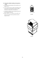
1. R410A additional charging absolutely must
be done through liquid charging.
2. The R410A refrigerant cylinder has a gray
base color, and the top part is pink.
3. The R410A refrigerant cylinder includes a
siphon tube. Check that the siphon tube is
present. (This is indicated on the label at
the top of the cylinder.)
4. Due to differences in the refrigerant, pres-
sure, and refrigerant oil involved in instal-
lation, it is not possible in some cases to
use the same tools for R22 and for R410A.
1 2 3 4
LA
LB
LC
A
B
Outdoor unit
09663
model
09663
model
48 model 48 model 48 model 36 model
Example:
●
Example of each tubing length
Main tubing Distribution joint tubing
LA = 131 ft. Outdoor side Indoor side
LB = 16 ft.
A = 7 ft. 1 = 98 ft.
LC = 16 ft.
B = 7 ft. 2 = 16 ft.
3 = 16 ft.
4 = 65 ft.
Balance tube
Liquid tube
Discharge tube
Suction tube
Use a hex wrench (width 5/32 inch)
and turn to the left to open.
Use a flathead screwdriver
and open by turning the part
with the screw groove to the
right, from " " to " "
Use a flathead screwdriver
and open by turning the part
with the screw groove to the
right, from " " to " "
Use a flathead screwdriver
and open by turning the part
with the screw groove to the
right, from " " to " "

19
●
Obtain liquid tubing size from Tables 1-3, 4, 5 and 9.
Main tubing
LA = ø5/8 (ft.) (Total capacity of indoor unit is 179,400 BTU/h) The longest tubing length in this example
LB = ø1/2 (ft.) (Total capacity of indoor unit is 131,600 BTU/h) (LA = 131 ft.)
LC = ø3/8 (ft.) (Total capacity of indoor unit is 83,800 BTU/h)
Distribution joint tubing
Outdoor side
A: ø3/8 (ft.) B: ø3/8 (ft.) (from outdoor unit connection tubing)
Indoor side
1: ø3/8 (ft.) 2: ø3/8 (ft.) 3: ø3/8 (ft.) 4: ø3/8 (ft.) (from indoor unit connection tubing)
●
Obtain charge amount for each tubing size
Note1: The charge amounts per 1 ft. are different for each liquid tubing size.
ø5/8 (ft.)
→
LA : 131 ft.
×
1.99 oz/ft. = 261 oz
ø1/2 (ft.)
→
LB : 16 ft.
×
1.38 oz/ft. = 22 oz
ø3/8 (ft.)
→
LC +
A – B + 1 – 4 : 225 ft.
×
0.602 oz/ft. = 135 oz
Total 418 oz
Additional refrigerant charge amount is 418 oz.
Be sure to check the limit density for
the room in which the indoor unit is
installed.
CAUTION
Note 2: Necessary amount of additional refrigerant charge per outdoor unit (CHDZ09663) is 42 oz. (See the Table 1-10-2.)
Note 1) Amount of additional charge per tubing length : 418 oz
Note 2) Amount of additional charge for outdoor unit : 84 oz (42+42)
Total of additional refrigerant charge amount : 502 oz
Therefore, the total of additional refrigerant charge amount reaches 502 oz.
Obtain overall refrigerant charge amount.
Overall refrigerant charge amount of the system indicates the calculated value shown above the additional charge amount
in addition to the total of the refrigerant charge amount (shown in the Table 1-6) at the shipment of each outdoor unit.
Refrigerant charge amount at shipment:
CHDZ09663 : 416 oz
CHDZ09663 : 416 oz
Additional charge amount : 502 oz
Grand total : 1334 oz
Therefore, overall refrigerant charge amount of the system reaches 1334 oz.
Remark:
Be sure to include the values in Table 1-10-2 Necessary Amount of Refrigerant Charge Per Outdoor Unit.

20
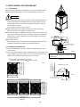
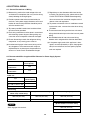
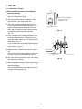
2. SELECTING THE INSTALLATION SITE
2-1. Outdoor Unit
AVOID:
●
heat sources, exhaust fans, etc.
●
damp, humid or uneven locations
●
indoors (no-ventilation location)
DO:
●
choose a place as cool as possible.
●
choose a place that is well ventilated.
●
allow enough room around the unit for air intake/
exhaust and possible maintenance.
●
use lug bolts or equal to bolt down unit, reducing vibration
and noise.
Installation Space
Install the outdoor unit where there is enough space for ven-
tilation. Otherwise the unit may not operate properly. Fig. 2-2
shows the minimum space requirement around the outdoor
units when 3 sides are open and only 1 side is shuttered, with
open space above the unit. The mounting base should be con-
crete or a similar material that allows for adequate drainage.
Make provisions for anchor bolts, platform height, and other
site-specific installation requirements.
CAUTION
●
Leave space open above the
unit.
●
Construct louvers or other
openings in the wall, if nec-
essary, to ensure adequate
ventilation.
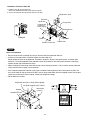
NOTE
●
Do not do any wiring or tubing within 1 ft. of the front
panel, because this space is needed as a servicing
space for the compressor.
●
Ensure a base height of 4 in. or more to ensure that
drainage water does not accumulate and freeze
around the bottom of the unit.
●
If installing a drain pan, install the drain pan prior to
installing the outdoor unit.
* Make sure there is at least 6 in. between the outdoor
unit and the ground.
Also, the direction of the tubing and electrical wiring
should be from the front of the outdoor unit.
Fig. 2-1
Fig. 2-2
Fig. 2-3
Out-
door
unit
Heat
source
Hot air
Exhaust fan
More than
2 in.
More than
1.7 ft.
* More than 4 in.
* More than 4 in.
* More than 4 in.
Example of installation of 2 units
(When wall height is below 6 ft.)
* However, be sure to ensure a space of 1 ft. or more at
either the right side or the rear of the unit.
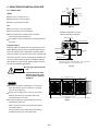
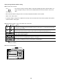
35
(Ceiling panel dimensions)
113 (Ceiling panel dimensions)
35
(Ceiling panel dimensions)
4435
(Ceiling panel dimensions)
31-1/8
(Installation hole pitch)
31-1/8
(Installation hole pitch)
7-7/8
31-1/8
(Installation hole pitch)
109-1/16 (Installation hole pitch)
7-7/8
35(Ceiling panel dimensions)
36-1/4 (Installation hole pitch)
37-1/2 (Maximum dimensions)
Unit: in.Top view
Page is loading ...
Page is loading ...
Page is loading ...
Page is loading ...
Page is loading ...
Page is loading ...
Page is loading ...
Page is loading ...
Page is loading ...
Page is loading ...
Page is loading ...
Page is loading ...
Page is loading ...
Page is loading ...
Page is loading ...
Page is loading ...
Page is loading ...
Page is loading ...
Page is loading ...
Page is loading ...
Page is loading ...
Page is loading ...
Page is loading ...
Page is loading ...
Page is loading ...
Page is loading ...
Page is loading ...
Page is loading ...
Page is loading ...
Page is loading ...
Page is loading ...
Page is loading ...
Page is loading ...
Page is loading ...
-
 1
1
-
 2
2
-
 3
3
-
 4
4
-
 5
5
-
 6
6
-
 7
7
-
 8
8
-
 9
9
-
 10
10
-
 11
11
-
 12
12
-
 13
13
-
 14
14
-
 15
15
-
 16
16
-
 17
17
-
 18
18
-
 19
19
-
 20
20
-
 21
21
-
 22
22
-
 23
23
-
 24
24
-
 25
25
-
 26
26
-
 27
27
-
 28
28
-
 29
29
-
 30
30
-
 31
31
-
 32
32
-
 33
33
-
 34
34
-
 35
35
-
 36
36
-
 37
37
-
 38
38
-
 39
39
-
 40
40
-
 41
41
-
 42
42
-
 43
43
-
 44
44
-
 45
45
-
 46
46
-
 47
47
-
 48
48
-
 49
49
-
 50
50
-
 51
51
-
 52
52
-
 53
53
-
 54
54


Sanyo FMHX2462 Installation Instructions Manual
- Category
- Split-system air conditioners
- Type
- Installation Instructions Manual
Ask a question and I''ll find the answer in the document
Finding information in a document is now easier with AI
Related papers
-
Sanyo DHX4852 Installation Instructions Manual
-
-
Sanyo DHX3652 User manual
-
-
-
-
Sanyo C3672R User manual
-
-
-
Other documents
-
Panasonic U-72MF1U9E User manual
-
-
-
-
Mitsubishi Electric PCA-A.KA5 Installation guide
-
Mitsubishi 250 YHA-A User manual
-
-
Air-Con Blue Series III Service Owner's manual
-
-