Page is loading ...

DIATROL
®
D SERIES
REPLACEMENT BLADDER INSTRUCTIONS
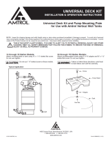
Figure 1 Figure 2 Figure 3 Figure 4
READ CAREFULLY THE REPLACEMENT
BLADDER INSTRUCTIONS TO AVOID
SERIOUS PERSONAL INJURY AND PROPERTY HAZARDS AND
TO ENSURE SAFE USE AND PROPER CARE OF THIS
PRODUCT.
EXPLOSION OR RUPTURE HAZARD. THE
EXPANSION TANK MUST BE OPERATED SO
THAT THE PRESSURE DOES NOT EXCEED THE MAXIMUM
WORKING PRESSURE.
THIS PRODUCT, LIKE MOST PRODUCTS
UNDER PRESSURE, MAY OVER TIME
CORRODE, WEAKEN AND BURST OR EXPLODE, CAUSING
SERIOUS OR FATAL INJURY, LEAKING OR FLOODING AND/
OR PROPERTY DAMAGE. TO MINIMIZE RISK, A LICENSED
PROFESSIONAL MUST INSTALL AND PERIODICALLY
INSPECT AND SERVICE THE PRODUCT. A DRIP PAN
CONNECTED TO AN ADEQUATE DRAIN MUST BE INSTALLED
IF LEAKING OR FLOODING COULD CAUSE PROPERTY
DAMAGE. DO NOT LOCATE IN AN AREA WHERE LEAKAGE
OF THE TANK OR CONNECTIONS COULD CAUSE PROPERTY
DAMAGE TO THE AREA ADJACENT TO THE APPLIANCE OR
TO LOWER FLOORS OF THE STRUCTURE.
Installation
1. Isolate tank from system.
2. Drain water from bladder.
3. Remove air valve core (Figure 1) to bleed remaining
air charge.
4. Remove drain plug (Figure 2).
5. Disconnect system connection.
6. Unbolt and remove system connection after
marking flanges in order to align during reassembly
(Figure 3).
7. Unbolt blind flange from tank and attach suitable
lifting equipment to lifting eye. Turn top flange
counter clockwise to wrap bladder around itself.
8. Push bladder flange into tank at system connection.
9. Pull old bladder from tank.
10. Unbolt blind flange (Figure 4) from old bladder and
remove old gasket.
NOTE: Inspect for shipping damage and notify freight carrier or store where purchased immediately if damage is present. To avoid risk of personal
injury and property damage, if the product appears to be malfunctioning or shows signs of corrosion, call a qualified professional immediately. Current
copies of the Product manual can be viewed at www.amtrol.com. Use proper safety equipment when installing.
THIS IS THE SAFETY ALERT SYMBOL. IT IS USED TO ALERT YOU TO POTENTIAL PERSONAL INJURY AND OTHER
HAZARDS. OBEY ALL SAFETY MESSAGES THAT FOLLOW THIS SYMBOL TO REDUCE THE RISK OF PERSONAL
INJURY AS WELL AS PROPERTY DAMAGE.

© 2016 AMTROL Inc. Part #: 9017-098 (08/16)
1400 Division Road, West Warwick, RI USA 02893
T: 800.426.8765 F: 800.293.1519
www.amtrol.com
Mark of the
Originator
11. Wash down inside walls of tank as necessary.
12. Mop up remaining water.
13. Dry out inside of tank (reversed vacuum cleaner or air line
from a compressor).
14. Clean out any remaining dirt.
15. Examine interior for any rust blisters and
remove them.
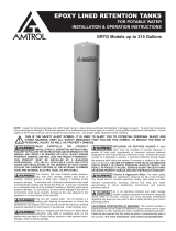
16. Fold new bladder lengthwise and tape at necessary intervals
(Figure 5).
17. Fold in bladder neck and tape.
18. Rebolt blind flange to new bladder and use
new gasket.
19. Working by hand, insert bladder into tank with flange pointing
to opening in system connection removing tape as it is
inserted into tank. Do not remove tape from bladder flange.
20. Find and pull bladder flange into position and remove tape.
Check through top flange opening to assure bladder is
not twisted.
21. Rebolt blind flange to tank. Torque to 25 ft. lbs.
22. Rebolt system connect after aligning flange marks (Figure 3).
Torque to 40-50 ft. lbs.
23. Install drain plug (Figure 2) using a liberal amount of
TITE-SEAL COMPOUND 55 or equal. This connection must
be absolutely airtight.
FAILURE TO PROPERLY SEAL VALVE CAP
WILL RESULT IN LOSS OF PRE-CHARGE
CAUSING TANK TO FAIL.
24. Install air valve core. Charge tank to 10% below system
pressure using dry air or nitrogen.
DANGER! EXPLOSION HAZARD. IF YOU ADJUST
THE PRE-CHARGE PRESSURE OR ADD
PRESSURE TO A TANK IS CORRODED OR DAMAGED OR WITH
DIMINISHED INTEGRITY THE TANK CAN BURST OR EXPLODE,
POSSIBLY CAUSING SERIOUS OR FATAL PERSONAL INJURY
AND/OR PROPERTY DAMAGE.
• ONLY ADJUST THE PRE-CHARGE AS DESCRIBED IN THIS
MANUAL WHEN THE TANK IS NEW OR WHEN THE INTEGRITY
OF THE TANK AND LACK OF INTERNAL OR EXTERNAL
CORROSION IS CONFIRMED.
• ONLYQUALIFIEDPROFESSIONALSSHOULDCHECK,ADJUST
OR RE-CHARGE THE PRE-CHARGE OF TANKS.
25. Using soapy water, check the drain fitting threads, air valve
core and flange joint for leakage.
26. Connect tank to system. Open fill-valve and check operation.
Always pre-charge tank before completing this step.
FAILURE TO FOLLOW THE ABOVE WARNINGS MAY RESULT
IN SERIOUS INJURY OR FATAL PERSONAL INJURY AND/OR
PROPERTY DAMAGE AND WILL VOID THE WARRANTY
Figure 5
Required Tooling & Supplies:
1. Plumbers Tool Box
2. Source of Compressed Dry Air or Nitrogen
3. Light with 20 ft. Cord
4. Power Extension Cord (as required)
5. Chain Block
6. Pressure Gauge and Air Valve Tool
(to remove valve core)
7. New AMTROL Bladder
IMPORTANT: If increasing pre-charge pressure above 55
psig the following steps must be followed:
a. Tank must be connected to the system with isolation valve open.
b. System must be pressurized to 24-30 psig, matching the pre-
charge setting of the tank.
c. Isolation valve needs to be closed.
d. The pre-charge pressure of the tanks can now be increased to
the recommended high pressure setting.
e. Bring system up to pressure and then open the isolation valve
to the tank.
Failure to follow these steps could result in damage to the
bladder and void all warranties.
/