Page is loading ...

SERVICE TECHNICIAN’S
TROUBLE SHOOTING GUIDE
2004-28 TSG-SOLO-9/04
prestige
Condensing
Water Boiler

Table of Contents
INTRODUCTION Page 1
SERVICING TIPS AND INSTRUCTIONS Page 3
CONTROL MODULE DISPLAY - GENERAL Page 5
PRESTIGE CONTROL MODULE DISPLAY Page 8
SOFT LOCKOUT ERROR CODE Page 9
HARD LOCKOUT ERROR CODE Page 14
COMBUSTION TEST/SETTINGS Page 20
INTERNAL WIRING Page 22
REPLACEMENT PARTS Page 24

Definitions
Indicates a potentially hazardous situation which, if ignored, can result in death, serious injury or sub-
stantial property damage.
Indicates special instructions on installation, operation or maintenance, which are important to the equip-
ment/product, but not related to personal injury hazards.
This guide is to be used in conjunction with the PRESTIGE Installation and Maintenance manual.
Procedures and servicing listed in this manual must be performed by a qualified service technician,
installer, service agency or gas supplier. Any procedures or service performed by an unqualified individ-
ual or service agency can result in severe personal injury, death or substantial property damage.
WARNING
NOTICE
WARNING
Introduction
1

Introduction
2
Introduction
This guide is to be used in conjunction with the Triangle Tube PRESTIGE Boiler Installation and Maintenance Manual.
Good Troubleshooting Practices
Before leaving for the job site:
Check your parts and tools
• Test equipment and tools you will need:
Electrical meter that tests both voltage and continuity
Temperature gauge or metering device
Manometer
Combustion Analyzer
Standard tools of the trade (wrenches, screwdrivers...)
• Parts to solve most problems
Control module PSRKIT18
Transformer with surge protection PSRKIT19
Blower with gasket PSRKIT13
Review all appropriate manuals before leaving for the job site
At the job site:
- Clarify problem
- Have the PRESTIGE manual and any other wiring, zone control or piping diagrams, or installation guides readily
available.
REMEMBER
Follow the Troubleshooting Guide step by step, always double checking your results. Skipping steps or not complet-
ing steps can lead to wrong conclusions, repeated visits to the job site, unhappy customers and unnecessary warran-
ty claims.

Servicing Tips and Instructions
3
Label all wires and wire connections prior to disconnecting when servicing any boiler controls. Wiring errors
can cause improper and dangerous operation. Always disconnect the power supply to the boiler before serv-
icing. Failure to comply could result in severe personal injury, death or substantial property damage.
Never bypass (jumper) any boiler control or device except for momentary testing when troubleshooting the
boiler as outlined in this guide, severe personal injury, death or substantial property damage can result.
Initial Troubleshooting Checks
- Ensure all wire connectors to the control module and sensors are securely connected.
- Ensure the maximum gas supply pressure does not exceed 13”w.c during flow or no flow conditions.
- Ensure the gas supply pressure is a minimum 5” w.c during flow conditions (burner firing on all gas appliances).
Control Module Fuses
The control module contains 2 internal replaceable fuses. Ensure the fuses are in working condition prior to
replacing the control module or any boiler component. If one of the fuses has blown, it will prevent the con-
trol module and/or boiler components from operating properly.
To check or replace the control module fuses:
1. Disconnect the external power supply to the boiler.
2. Remove the front jacket panel of the boiler by removing the mounting screws along the top edge.
3. Remove the electical quick connects on the control and the black plastic housing cover off the control module.
Use care not to damage the cover when removing it.
4. Inspect both fuses to determine if blown.
5. The control module is supplied from the factory with 2 spare fuses, a 5 amp fast acting fuse and a 4 amp slow
acting fuse, attached to the control module cover.
6. When replacing the fuses ensure the amp rating and type of the fuse matches the replacement fuse. Reference
Fig. 1, page 4 for amperage and location of the fuses.
Do not bypass any fuse with a jumper. Do not replace any fuse with a fuse that is not specified. Failure to
comply could result in severe personal injury, death or substantial property damage.
7. Re-install the control module cover, electrical quick connects and the front jacket panel when completed.
WARNING
NOTICE
WARNING
WARNING

8. Reconnect the external power supply to the boiler and perform the verification of operation steps as outline in
the Prestige Installation Manual.
After completing any servicing of the boiler verify proper operation of the boiler. Steps to verify proper oper-
ation are outlined in the Start-Up Preparation in the PRESTIGE Installation manual. Failure to comply could
result in severe personal injury, death or substantial property damage.
WARNING
Servicing Tips and Instructions
4
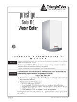
F1 Fuse Rating
5 - AMP/250V
Fast Acting
for 120V-High Voltage
120V-High Voltage
Electrical Quick
Connect
F3 Fuse Rating
4 - AMP/250V
Slow Acting
for 24V-Low Voltage
Control
Module
Fig. 1 Control Module Fuse Locations (Housing Cover Removed)

Standby Mode
After the boiler is turned on, the control panel will display
STANDBY mode as shown in the figure above.
This is the standard mode for the PRESTIGE. The control
automatically returns to this mode after 20 minutes if no
keys have been pressed on the display. Any parameters
that were modified are then enabled.
The first character shows (on the left side of the display)
the current status of the boiler depending on the condition
of both the boiler and the burner. The last 3 characters
indicate the start temperature. See page 8 for additional
information.
If the burner is blocked due to a “soft” lockout, the display
alternates between a 9 followed by the boiler outlet tem-
perature and “b” with a two digit error code. See page 9 -
13 for detailed information on the corrective and preven-
tive actions for the soft lockouts.
TO TEMPORARY PLACE THE BURNER INTO HIGH
FIRE MODE: press the MODE button with + button simul-
taneously and hold for 2 or 3 seconds.
TO TEMPORARY PLACE THE BURNER INTO LOW
FIRE MODE: press the MODE button with - button simul-
taneously and hold for 2 or 3 seconds.
The control module will maintain the fixed firing
rate for approximately 10 minutes before default-
ing to normal operating conditions.
Press the + and - button simultaneously to deactivate the
high or low fire mode.
NOTICE
S
tb
Y
Control Module Display - General
STANDBY, no demand for heat
Fan prepurge (10 seconds) or post purge cycle
(30 seconds)
Ignition sequence
Burner ON for space heating (CH)
Burner ON for domestic water heating (DHW)
Pre-check for air flow prior to prepurge cycle
Burner OFF due to reaching temperature
set point
Post pump cycle for domestic hot water
(30 seconds)
Post pump cycle for primary space heating
(1 minute)
Burner blocked:
Supply temperature too high (203 F) .Burner will
remain OFF until outlet temperature drops
below 200 F
Return temperature too high (203 F). Burner
will remain OFF until return temperature drops
below 200 F
Return temperature is measured higher than
supply
temperature. Burner will remain OFF
until corrected.
Supply temperature increased too quickly.
Burner will remain OFF for a 10 minute period.
Burner will recycle, increasing waiting period 1
minute for a max. 15 minutes
Factory supplied LWCO pressure device or
external limit (terminals 15 & 16) is OPEN.
Burner off for 150 seconds, auto
reset.
0
1
18
0
18
0
18
0
18
0
18
0
18
0
18
0
18
0
18
0
18
0
2
3
4
5
6
7
8
9
1
8
b
1
9
b
2
4
b
2
5
b
2
6
b
2
Display
Boiler function
No blower signal
Blower signal present, Burner will remain OFF
until condition terminates
Temperature rise between the supply and return
is more than 72 F. Burner will remain OFF for
150 seconds. Burner will recycle increasing
wating period 1 minute for a max. 20 cycle.
Short circuit measured across flue temperature
sensor terminals.
Burner OFF until corrected.
Open circuit measured across the flue
temperature sensors.
Flue temperature greater than 241 F less than
250 F. Burner off for 150 seconds
Wait for the blower to start
8
b
2
2
9
b
3
0
b
3
5
b
4
0
b
5
2
b
6
5
b
Internal check
Test function: Burner on, high fire mode
Test function: Burner on, low fire mode
A
18
0
18
0
18
0
H
L
Display
Boiler function
5

Parameter Mode
To access PARAMETER mode when the system is in
STANDBY mode, press the MODE button once.
To scroll through the list of parameters, simply press the
“STEP” button. To modify a parameter value, use the + or
- keys. Then press “STORE” to save the value you just
changed. The display flashes once to confirm the data has
been saved.
To activate the parameters you changed, press MODE
once more (which brings you into the INFORMATION
mode). However, if you do not press a key, the system
returns to STANDBY mode after 20 minutes and automat-
ically enables the changes.
Note 1: The factory setting of this parameter is 01, which
is the ON setting for domestic hot water. To turn the
domestic ON or OFF press and hold the “-” button, while
in the STBY (standby) mode until the display shows the
desired setting “dOFF” or ‘d---” and than release. Where
“---” is the temperature set point and the ON position.
Note 2: The factory setting of this parameter is 01, which
is the ON setting for space heating. To turn the space
heating ON or OFF press and hold the “+” button, while in
the STBY (standby) mode until the display shows the
desired setting “cOFF” or “c---” and than release. Where “-
--” is the temperature set point and the ON position.
If Parameter 2 and/or Parameter 3 is adjusted to a set-
ting of “00” or “02” the burner will not respond when
a call for heat is indicated.
Information Mode
To switch from STANDBY mode to INFORMATION mode,
press MODE twice.
Press STEP until the system displays the information you
need. The point located behind the first position flashes to
indicate that the boiler is in INFO mode.
If STEP is pressed after parameter 9, the display will show
A-22.
Note 3: Parameter 3 will display the measured storage
domestic temperature of an IDWH when an optional
IDWH sensor is utilized. Parameter 9 will display the rate
of increase in the domestic storage temperature ºF/sec.
NF
O
I
NOTICE
AR
A
P
Control Module Display - General
6
AR
A
P
MODE
NF
O
I
MODE
Key:
Display
Pressing MODE once
Pressing MODE twice
Measured outlet (supply) water
temperature
Measured inlet (return) water
temperature
This parameter is not used (Note 3)
Measured outdoor temperature
(Optional outdoor sensor required)
1.
2
1
-
18
0
6
0
2
2
5
5
3
4
STEP
STEP
STEP
STEP
Key:
Display
Description of parameters
Measured flue temperature
Rate of increase in the outlet water
temperature F/sec
Rate of increase in the return water
temperature F/sec
This parameter is not used (Note 3)
6.
7
18
0
1
1
0
0
8
9
.
.
.
.
.
STEP
Calculated (target) outlet water
temperature
5.
15
0
STEP
STEP
STEP
STEP
Domestic Hot W ater Setting
Dom estic Hot Water Setup (See Note 1)
Space Heating Mode (See Note 2)
Maximum tem perature in space heating
(CH) m ode. In applications using an
outdoor sensor, this is the boiler
target temperature at an outd
o
temperature of 0 F or less.
1.
2
15
0
0
1
0
1
8
1
0
AR
A
3
4
P
.
.
.
.
MODE
STEP
STEP
STEP
STEP
Key:
Screen
Key:
Display
Description of parameters
Pressing MODE once

Error Hard Lockout Mode
If a fault occurs while the boiler is running, the system
goes into lockout and the display starts to flash with the
first digit as an E and the next two digits give the code for
this fault.
For detailed information on the corrective and preventive
actions for the hard lockout, see pages 14-19.
Control Module Display - General
Gas valve harness not properly connected
Failed ignition after 5 attempts
Power supply lost after lockout occured
Internal control failure
Internal control failure
E
E
0
2
03
0
4
0
8
0
9
E
E
E
Display
Hard Lockout
Internal control failure
0
5
E
Internal control failure
0
6
E
Internal control failure
0
7
E
Flame detected prior to burner startup
E
0
0
Internal control failure
External limit (terminal 13 & 14) control is OPEN
Blower signal does not reset to zero
No blower signal present
Supply temperature sensor is short circuited
1
1
1
2
1
5
1
6
2
9
2
8
E
E
E
E
E
E
Flue temperature exceeds 250 F
5
2
E
Internal Control error - failure to read parameters
6
1
E
Return temperature is short circuited
Supply temperature sensor is OPEN
Return temperature sensor is OPEN
Internal control failure
Internal control failure
Inadequate power supply to the fan
E
E
3
1
32
3
6
3
7
4
4
60
6
5
E
E
E
E
E
Return temperature exceeds 212 F
Supply temperature increased too rapidly
Internal control failure
Internal control failure
Internal control failure
Internal control failure
Internal control failure
1
7
1
9
2
5
1
3
E
E
E
E
Supply Temperature exceeds 212 F
1
8
E
E
1
4
7

Boiler control display is blank
- Check for 120 volts at terminals 1 and 2 of the 120V terminal strip
• If no power is measured check the external power supply, external fuse or breaker.
- Check the internal fuse F1 by locating the control module and removing the black housing. The internal fuse F1 is
located in the right corner of the control module near the 120V high voltage electrical quick connect on the control
as shown in Fig. 1, page 4. 120 volts should be measured across the fuse. See Servicing Tips and Instructions,
page 3, for accessing the internal fuses of the control module.
• If fuse F1 has blown and 120 volts is not present, replace the fuse with a 5-amp/250V fast acting fuse. Check
the wiring for possible causes for the fuse to blow.
- Check external wiring at 120V terminal strip and boiler internal wiring, ensure all wiring is properly connected, in
good condition and all control module and boiler connections are secure.
• Correct/replace any mis-wiring or wiring components if needed. If problem continues replace the control module.
Boiler display shows UI.25
- Check transformer connections
- Check the internal fuse F3 by locating the control module and removing the black housing. The internal fuse F3 is
located in the center of the control module as shown in Fig. 1 page 4.
See servicing tips and instructions, page 3, for accessing the internal fuses of the control module.
• If fuse F3 has blown, replace the fuse with a 4-amp/250V slow acting fuse. Check external boiler wiring for
exteral source of 24V backfeed.
Boiler display shows a 0 for the first digit on the left followed by 2 or 3 digits (boiler tem-
perature)
- Check to see if room and DHW thermostats are satisfied.
• If the thermostats are satisfied the boiler is off due to no call for heat. Turn up a thermostat and the boiler should
begin ignition sequence.
- If the room thermostat or DHW thermostat is calling for heat and the boiler is not firing and the boiler is below the
maximum operating temperature.
• Check and verify Parameters 2 and 3 are correct as outlined on page 6. Both parameters should be set as
“01”, which turns DHW and CH modes ON.
• Temporarily jump low voltage terminals 7 and 8 on the 24V terminal strip. If boiler operates check the room
thermostat wiring and thermostat control. Replace as needed. Remove jumper when completed.
• Temporarily jump low voltage terminals 11 and 12 on the 24V terminal strip. If boiler operates check the DHW
thermostat wiring and thermostat control. Replace as needed. Remove jumper when completed.
• Disconnect power to the boiler. Check all wiring and wiring connections and compare to the wiring diagram.
Ensure all wiring and wiring connection are in good condition and secure. If necessary, replace complete wiring
harness.
• Check for 24 volts across the control module internal fuse F3, which is located toward the middle of the con-
trol and positioned vertically see Fig. 1 page 4. If necessary replace the fuse. See Serving Tips and
Instructions, page 3, for accessing the internal fuses of the control module.
• If all the above steps fail to resolve the problem, replace the control module.
Boiler display shows a number of 1 to 8 for the first digit on the left followed by 2 or 3 dig-
its (boiler temperature)
- The boiler is in normal operating mode. Reference the boiler installation manual for detailed explanation of the boiler
operation.
Prestige Control Module Display
8

If the primary boiler supply water temperature exceeds 202ºF, the burner will
shut down until the supply temperature drops below 200ºF. The boiler circula-
tor will continue operating.
• This problem should only occur if the heat load demand is less than
the low input-firing rate of the boiler, typically found on small single
heat zones and there is a potential flow issue.
- Verify the boiler and heating system are filled with water and the
LWCO is operating properly.
- Ensure the boiler and heating system have been properly purged
and there is no entrapped air.
- Inspect and verify heating system piping and its components.
Ensure piping is per the recommendations given in the Prestige
Installation Manual or per other approved/recognized designed
configurations.
• Use a temperature-metering device to measure the supply water tem-
perature leaving the boiler. Compare this measured temperature with
the display temperature (INFO Mode display, “1” is the first digit on the
left followed by the temperature.)
- Replace the supply temperature sensor if the temperature com-
parison is largely varied by more than 10ºF.
- Replace the control module if the sensor replacement does not
resolve the problem.
• Ensure system and/or zone circulators are operating properly
If the primary boiler return water temperature exceeds 202ºF, the burner will
shut down until the return temperature drops below 200ºF. The boiler circula-
tor will continue operating.
• This problem rarely occurs unless the boiler experiences an Error
Code 18 and the system is charged with a water temperature in
excess of 202ºF
- Verify the boiler and heating system are filled with water and the
LWCO is operating properly.
- Ensure the boiler and heating system have been properly purged
and there is no entrapped air.
- Inspect and verify heating system piping and its components.
Ensure piping is per the recommendations given in the Prestige
Installation Manual or per other approved/recognized designed
configurations.
- Ensure the boiler piping is correct and the water flow is not
reversed or pipes are cross connected.
• Use a temperature-metering device to measure the return water tem-
perature entering the boiler. Compare this measured temperature with
the display temperature (INFO Mode display, “2” is the first digit on the
left followed by the temperature.)
- Replace the return temperature sensor if the temperature com-
parison is largely varied by more than 10ºF.
- Replace the control module if the sensor replacement does not
resolve the problem.
Soft Lockout Error Code
9
High Temperature Limit,
Boiler Return
Code
High Temperature Limit,
Boiler Supply
b- 18
b- 19
Error Condition
Correcting Error Condition
The boiler will display Soft Lockouts with a flashing “9”, then “b” as the first digit on the left of the display followed by a
steady two digit code. The boiler will automatically reset a Soft Lockout once the condition has been corrected and
returned to standard operating condition.

If the primary boiler return water temperature exceeds the boiler supply temper-
ature, the burner will shut down until the boiler return temperature drops below
the boiler supply temperature. The boiler circulator will continue operating.
• The following items should be checked:.
- Verify the boiler and heating system are filled with water and the
LWCO is operating properly.
- Ensure the boiler and heating system have been properly purged
and there is no entrapped air.
- Inspect and verify heating system piping and its components.
Ensure piping is per the recommendations given in the Prestige
Installation Manual or per other approved/recognized designed
configurations.
- Ensure the boiler piping is correct and the water flow is not
reversed or pipes are cross connected.
• Use a temperature-metering device to measure the supply water tem-
perature leaving the boiler. Compare this measured temperature with
the display temperature (INFO Mode display, “1” is the first digit fol-
lowed by the temperature.)
- Replace the supply temperature sensor if the temperature com-
parison is largely varied by more than 10ºF.
• Use a temperature-metering device to measure the return water tem-
perature entering the boiler. Compare this measured temperature with
the display temperature (INFO Mode display, “2” is the first digit fol-
lowed by the temperature.)
- Replace the return temperature sensor if the temperature compar-
ison is largely varied by more than 10ºF.
• Replace the control module if the sensor replacement does not resolve
the problem.
If the primary boiler supply water temperature rate of increase is deemed too
quick, the burner will shut down for a 10 minute period. If the condition is not
corrected during the next cycle, the burner shut down period of 10 minutes will
increase an additional minute. The boiler will continue for 5 cycles until a
“hard” lockout will occur.
• This problem will occur if the flow rate on the boiler is too low or if there
is no flow. Check for the following conditions:
- Verify the boiler and heating system are filled with water and the
LWCO is operating properly.
- Ensure the boiler and heating system have been properly purged
and there is no entrapped air.
- Inspect and verify heating system piping and its components.
Ensure piping is per the recommendations given in the Installation
Manual or per other approved/recognized designed configurations.
• Verify and ensure the boiler space heating CH circulator is operating
properly.
- Check and verify 120V at the circulator wiring in the circulator junc-
tion box. If no voltage is measured, check circulator wiring and
connections.
- Check and verify 120V at the MCBA control module along termi-
nals X1-4 and X1-3. If no voltage is measured, replace control
module. Check circulator wire harness and replace if needed if
voltage is measured at the control module.
Soft Lockout Error Code
10
Code
Error Condition
Correcting Error Condition
High Temperature Limit,
Boiler Supply and Return
b- 24
High Temperature Limit,
Boiler Supply
b- 25

• Verify and ensure the external DHW circulator is operating properly.
- Check and verify 120V at the circulator wiring in the circulator
junction box. If no voltage is measured, check circulator wiring
and connections.
- Check and verify 120V at the 120V terminal strip, terminals 4 and
5 inside the boiler enclosure. Check circulator wire harness and
replace if needed if voltage is measured at the control module.
• Verify pump is properly sized for the flow rate required based on the head
loss of the system. Reference the installation manual for pump curves and
boiler pressure drop. Consult the circulator manufacturer for additional
pump curve data or for assistance in sizing a circulator properly.
If the LWCO device is determined to be open by the control module
the boiler will remain in a shut down mode until the condition is cor-
rected. Once the condition is corrected the boiler will remain in the
shut down mode for an additional 150 seconds before startup.
- Check the pressure gauge on the boiler and ensure the system is
at minimum 10 psig.
- Ensure proper operation of the boiler make up system and fill
valve.
• Check continuity across the LWCO terminals for closed contacts if the
boiler system pressure gauge reads 10 psig or greater.
- Replace the LWCO device if the continuity shows an open circuit
and the system pressure is 10 psig or greater.
- Check the wiring and contacts from the LWCO to the control mod-
ule terminals if the continuity check shows a close circuit.
Replace the low voltage wiring harness if needed.
- Replace control module if the replacement of the wiring harness
does not resolve the problem.
Will occur if during the ignition sequence the blower does not start. The boiler
display will indicate a status code of 5 during the ignition sequence.
• Disconnect the connector at the blower. Restart the boiler sequence
and check for 35Vdc at the connector between the black and white
wires (pin 1 & 5).
- If 35Vdc is not present at the connector, inspect the wiring har-
ness and replace if necessary. Replace the control module if wire
harness replacement does not resolve the problem.
-- If 35Vdc is present at the connector, reconnect the wire harness
to the blower and ensure a secure connection. Replace the blow-
er assembly if problem is not resolved.
The control module is detecting the blower in operation when it should not be.
• Check and verify the wiring from the blower to the control module is
correct as shown in the appliance wiring schematic, page 22 and 23.
- Replace the wiring harness from the control module to the blower.
Replace the blower if the replacement of the wiring harness does
not resolve the problem. Replace control module if blower
replacement does not resolve the problem.
Soft Lockout Error Code
11
Code
Error Condition
Correcting Error Condition
LWCO Device
b- 26
Blower Assembly
b- 28
b- 25
High Temperature Limit,
Boiler Supply (continued)
Blower Assembly
b- 29

If the primary boiler water temperature differential between the supply and the
return is too high (greater than 72ºF), the burner will shut down for a 150 sec-
ond period. The circulator will continue circulating until the start of the next
cycle. If the condition is not corrected during the next cycle, the burner shut
down period of 150 seconds will increase an additional minute. The boiler will
continue for 22 cycles until a “hard “ lockout will occur.
• This problem will occur if the flow rate and demand on the boiler is too
low. Check for the following conditions:
- Verify the boiler and heating system are filled with water and the
LWCO is operating properly.
- Ensure the boiler and heating system have been properly purged
and there is no entrapped air.
- Inspect and verify heating system piping and its components.
Ensure piping is per the recommendations given in the Installation
Manual or per other approved/recognized designed configurations.
- Ensure the piping system pressure drop is within the flow rate
parameters of the circulator.
• Verify and ensure the boiler space heating CH circulator is operating
properly.
- Check and verify 120V at the circulator wiring in the circulator
junction box. If no voltage is measured, check circulator wiring
and connections.
- Check and verify 120V at the MCBA control module along termi-
nals X1-4 and X1-3, see page 22. If no voltage is measured,
replace control module. Check circulator wire harness and
replace if needed if voltage is measured at the control module.
• Verify and ensure the external DHW circulator is operating properly.
- Check and verify 120V at the circulator wiring in the circulator
junction box. If no voltage is measured, check circulator wiring
and connections.
- Check and verify 120V at the 120V terminal strip between termi-
nals 4 and 5 inside the boiler enclosure. Check circulator wire
harness and replace if needed if voltage is measured at the con-
trol module.
The control module detects a short or jumped out condition of the flue tem-
perature sensor. This code will also appear briefly prior to a “hard” lockout if
the flue gas temperature exceeds 250ºF. The burner will remain off until the
condition is corrected.
• Inspect the flue temperature sensor and wiring, ensure it is secure
and in good condition, replace as needed.
- Replace the sensor and wiring if problem persists. If replacement
of sensor and wiring does not resolve the problem, replace the
control module.
Soft Lockout Error Code
12
Code
Error Condition
Correcting Error Condition
Flue Temperature Sensor
b- 35
b- 30
High Temperature Limit,
Boiler Supply and Return
Temperature Differential is
greater than 72ºF

Soft Lockout Error Code
13
Flue Temperature Sensor
b- 40
Blower Assembly
b- 65
Code
Error Condition
Correcting Error Condition
The control module detects the flue temperature sensor as “open”, which is
typically an improper or missing connection at the sensor.
• Inspect the flue temperature sensor and wiring, ensure it is secure
and in good condition, replace as needed.
- Replace the sensor and wiring if problem persists. If replacement
of sensor and wiring does not resolve the problem, replace the
control module.
The control module detects the flue temperature greater than 241ºF, less than
250ºF. Burner off for 150 seconds.
• This is an indication the heat exchanger flue ways may need clean-
ing. Reference the Maintenance section of the installation manual for
procedures on cleaning the flue side of the heat exchanger.
• Isolate the boiler from the boiler system piping and drain the boiler
heat exchanger. Flush the boiler heat exchanger several times,
checking the discharge water for signs of scale or sediment.
• Inspect the flue temperature sensor and wiring, ensure it is secure
and in good condition, replace as needed.
- Replace the sensor and wiring if problem persists. If replacement
of sensor and wiring does not resolve the problem, replace the
control module.
The control module does not detect proper blower operation during a call for
heat.
• Disconnect the 35Vdc connector at the blower. Restart the boiler
sequence and check for 35Vdc at the connector between the black
and white wires (pin 1 & 5).
- If 135Vdc is not present at the connector, inspect the wiring har-
ness and replace if necessary. Replace the control module if the
wire harness replacement does not resolve the problem.
- If 35Vdc is present at the connector, reconnect the wire harness
to the blower and ensure a secure connection. Replace the blow-
er assembly if problem is not resolved.
Flue Temperature Sensor
b- 52

This error will occur if the control module detects a burner flame (flame signal)
prior to the ignition sequence.
• This problem maybe related to the burner operating too hot due to
poor combustion. The flame pattern and combustion should be test-
ed at both high fire and low fire inputs. The flame should be com-
pletely on the burner head and blue without yellow tips during high
fire. Reference page 5 regarding high and low fire input procedures.
Reference page 20 for combustion requirements.
- If the flame is not deemed acceptable and the application is
propane, check and verify the propane orifice for proper size (ref-
erence page 20 for orifice sizes). Ensure the propane orifice is
properly seated in the gas valve gasket.
• Inspect the burner head through the burner sight port during shut
down sequence of the boiler.
- If the flame remains after the shut down sequence, the gas valve
maybe leaking. Check and verify the gas pressure is less than 13
inches w.c. If the gas pressure is less than 13 inches w.c.,
replace the gas valve.
This error will occur if the boiler has failed to establish flame detection during
the ignition sequence. The lockout will occur after 5 tries.
• If no ignition spark occurs during the ignition sequence:
- Check the ignition electrode cable, the electrode boot connector
and all connections, ensure all are in good condition. Replace if
damaged.
- Inspect the insulation of the electrode cable and the electrode
igniter; ensure there is no damage. Replace as needed.
- Check the ground lead for a secure connection from the control
module ground to the burner mounting plate. Use a ground con-
tinuity check to verify a good ground.
• If there is an ignition spark during the ignition sequence, but no flame:
- Verify the manual shutoff valve on the gas supply piping is in the
OPEN position.
- Check and verify the gas pressure at the inlet of the valve during
ignition sequence. Ensure the gas pressure maintains a mini-
mum 5 inches w.c during ignition sequence. Note: All gas appli-
ances within the building should be operating during this meas-
urement.
- Check and verify all gas piping is free of obstructions and has
been purged of all air.
- Check the gas meter for indications of gas flow during the ignition
sequence.
- Remove the ignition electrode to inspect for damage. Clean any
white oxides off the electrode if necessary. Replace the electrode
if damaged or will not clean.
- Replace the gas valve rectifier cable.
- Remove and inspect the gas valve and venturi gas ports. Ensure
ports are free of obstructions.
Hard Lockout Error Code
14
Code
Error Condition
Correcting Error Condition
The boiler will display a Hard Lockout with an E as the first digit on the left of display followed by a two-digit code. The
boiler must be manually reset by pressing the RESET button on the display once the condition has been corrected. A
Hard Lockout will occur when boiler conditions, that are considered critical in terms of safety, are not met or exceeded.
Flame Detection Error
E- 00
Failed Ignition Error
E- 02

- If the above items have been completed and verified, replace the
gas valve.
• Flame is established during the ignition sequence, but not maintained.
This problem may be due to low flame signal detection by the control
module.
- Inspect the flame pattern on the burner head during high and low
fire inputs. Inspect and clean the burner head if necessary.
Replace the burner head if damage. Reference page 5 regarding
high and low fire input procedures.
- Check the input rate of the boiler at the gas meter during high fire
input. If the gas meter measured rate is not at or below 15% of
the boiler rating, replace the gas valve.
Note: The length of venting and combustion air piping will affect the
measure boiler rating.
- Check the ground lead for a secure connection from the control
module ground to the burner mounting plate. Use a ground con-
tinuity check to verify a good ground.
- Remove the ignition electrode to inspect for damage. Clean any
white oxides off the electrode if necessary. Replace the electrode
if damaged or will not clean.
- If the above items have been completed and verified, replace the
control module.
• Ensure gas valve rectifier cable is properly connected to the gas valve
and secured.
Reset the boiler control module and retry ignition sequence and boiler opera-
tion. If problem continues, replace the rectifier cable.
This error will occur if power to the boiler is lost after a lockout has occurred.
The boiler must be manually reset and the original lockout code will be lost.
• This error will also occur if the service technician tries to reset a hard
lockout by turning the boiler OFF and then ON as an attempt to reset
the boiler.
• Verify polarity and proper ground on incoming 120V power connections
• This error may occur in rare cases if there is power interruption, surge
or “Dirty” voltage. An uninterruptible power supply may be installed on
the incoming voltage to the boiler.
Reset the boiler control module and retry ignition sequence and boiler opera-
tion. If problem continues, replace the control module.
Reset the boiler control module and retry ignition sequence and boiler opera-
tion. If problem continues, replace the control module.
Reset the boiler control module and retry ignition sequence and boiler opera-
tion. If problem continues, replace the control module.
Reset the boiler control module and retry ignition sequence and boiler opera-
tion. If problem continues, replace the control module.
Reset the boiler control module and retry ignition sequence and boiler opera-
tion. If problem continues, replace the control module.
Hard Lockout Error Code
15
Code
Error Condition
Correcting Error Condition
E- 02
Gas Valve Harness
E- 03
Loss of Power
E- 04
Internal Failure
E- 05
Internal Failure
E- 06
Internal Failure
E- 07
Internal Failure
E- 08
Internal Failure
E- 09
Failed Ignition Error
(continued)

Reset the boiler control module and retry ignition sequence and boiler opera-
tion. If problem continues, replace the control module.
• An external limit control connected at the 24V terminal strip, between
terminals 13 and 14 is open, breaking the circuit. Determine reason
for the limit to be open and correct condition.
- If no external limit is used, then check and verify connection of the
factory applied jumper across terminals 13 and 14.
- If the external limit is closed, then check the boiler internal wiring
connections and repair or replace if necessary. Remove the exter-
nal limit and apply a temporary jumper across terminals 13 and 14
and verify operation.
Reset the boiler control module and retry ignition sequence and boiler opera-
tion. If problem continues, replace the control module.
Reset the boiler control module and retry ignition sequence and boiler opera-
tion. If problem continues, replace the control module.
Reset the boiler control module and retry ignition sequence and boiler opera-
tion. If problem continues, replace the control module.
Reset the boiler control module and retry ignition sequence and boiler opera-
tion. If problem continues, replace the control module.
Reset the boiler control module and retry ignition sequence and boiler opera-
tion. If problem continues, replace the control module.
This error will occur if the boiler supply water temperature exceeds 212ºF.
• The following items should be checked:.
- Verify the boiler and heating system are filled with water and the
LWCO is operating properly.
- Ensure the boiler and heating system have been properly purged
and there is no entrapped air.
- Inspect and verify heating system piping and its components.
Ensure piping is per the recommendations given in the Installation
Manual or per other approved/recognized designed configurations.
• Use a temperature-metering device to measure the supply water tem-
perature leaving the boiler. Compare this measured temperature with
the display temperature (INFO Mode display, “1” is the first digit fol-
lowed by the temperature.)
- Replace the supply temperature sensor if the temperature com-
parison is largely varied by more than 10ºF.
- Replace the control module if the sensor replacement does not
resolve the problem.
Hard Lockout Error Code
16
Code
Error Condition
Correcting Error Condition
Internal Failure
E- 11
External Limit Lockout
E- 12
Internal Failure
E- 13
Internal Failure
E- 14
Internal Failure
E- 15
Internal Failure
E- 16
Internal Failure
E- 17
High Temperature Limit,
Supply Temperature
E- 18

This error will occur if the boiler return water temperature exceeds 212ºF.
• This problem rarely occurs unless the boiler experiences an Error
Code 18 and the system is charged with a water temperature in
excess of 212ºF. The following items should be checked:
- Verify the boiler and heating system are filled with water and the
LWCO is operating properly.
- Ensure the boiler and heating system have been properly purged
and there is no entrapped air.
- Inspect and verify heating system piping and its components.
Ensure piping is per the recommendations given in the Installation
Manual or per other approved/recognized designed configurations.
- Ensure the boiler piping is correct and the water flow is not reversed
or pipes are cross-connected.
• Use a temperature-metering device to measure the return water tem-
perature leaving the boiler. Compare this measured temperature with
the display temperature (INFO Mode display, “2” is the first digit fol-
lowed by the temperature.)
- Replace the return temperature sensor if the temperature compar-
ison is largely variedby more than 10ºF.
- Replace the control module if the sensor replacement does not
resolve the problem.
This error will occur if the boiler supply water temperature rate of increase is
deemed too rapid. The control module will display a soft lockout of b_25 and
initiate a recycle sequence. After 5 cycles the boiler will go into a hard lockout.
• This problem will occur if the flow rate and demand load on the boiler
are too low. Check for the following conditions:
- Verify the boiler and heating system are filled with water and the
LWCO is operating properly.
- Ensure the boiler and heating system have been properly purged
and there is no entrapped air.
- Inspect and verify heating system piping and its components.
Ensure piping is per the recommendations given in the Installation
Manual or per other approved/recognized designed configurations.
• Verify and ensure the boiler central heating CH circulator is operating
properly.
- Check and verify 120V at the circulator wiring in the circulator junc-
tion box. If no voltage is measured, check circulator wiring and
connections.
- Check and verify 120V at the MCBA control module along termi-
nals X1-4 and X1-3. If no voltage is measured, replace control
module. Check circulator wire harness and replace if needed if
voltage is measured at the control module.
• Verify and ensure the external DHW circulator is operating properly.
- Check and verify 120V at the circulator wiring in the circulator junc-
tion box. If no voltage is measured, check circulator wiring and
connections.
- Check and verify 120V at the 120V terminal strip between termi-
nals 4 and 5 inside the boiler enclosure. Check circulator wire har-
ness and replace if needed, if voltage is measured at the control
module.
Hard Lockout Error Code
17
Code
Error Condition
Correcting Error Condition
High Temperature Limit,
Return Temperature
E- 19
High Temperature Limit,
Supply Temperature rate
of increase
E- 25

• Verify pump is properly sized for the flow rate required based on the
head loss of the system. Reference the installation manual for pump
curves and boiler pressure drops. Consult the circulator manufacturer
for additional pump curve data or for assistance in sizing a circulator
properly.
This error will occur if during the ignition sequence the blower does not start.
The boiler display will indicate a status code of 5 during the ignition sequence
for 4 minutes before locking out.
• Disconnect the connector at the blower. Restart the boiler sequence
and check for 35Vdc at the connector between the black and white
wires (pin 1& 5).
- If 35Vdc is not present at the connector, inspect the wiring harness
and replace if necessary. Replace the control module if wire har-
ness replacement does not resolve the problem.
- If 35Vdc is present at the connector, reconnect the wire harness to
the blower and ensure a secure connection. Replace the blower
assembly if problem is not resolved.
The control module is detecting the blower in operation when it should not be.
• Check and verify the wiring from the blower to the control module is
correct as shown in the appliance wiring schematic, page 22.
- Replace the wiring harness from the control module to the blower.
Replace the blower if the replacement of the wiring harness does
not resolve the problem. Replace control module if blower replace-
ment does not resolve the problem.
The control module detects a short or jumped out condition of the boiler supply
(outlet) temperature sensor.
• Inspect the boiler supply temperature sensor and wiring, ensure it is
secure and in good condition, replace as needed.
- Replace the sensor and wiring if problem persists. If replacement
of sensor and wiring does not resolve the problem, replace the
control module.
The control module detects a short or jumped out condition of the boiler return
(inlet) temperature sensor.
• Inspect the boiler return temperature sensor and wiring, ensure it is
secure and in good condition, replace as needed.
- Replace the sensor and wiring if problem persists. If replacement
of sensor and wiring does not resolve the problem, replace the
control module.
The control module detects the boiler supply (outlet) temperature sensor as an
open circuit.
• Inspect the boiler supply temperature sensor and wiring, ensure it is
secure and in good condition, replace as needed.
- Replace the sensor and wiring if problem persists. If replacement
of sensor and wiring does not resolve the problem, replace the
control module.
Hard Lockout Error Code
18
Code
Error Condition
Correcting Error Condition
Blower Assembly
E- 28
Boiler Supply
Temperature sensor
E- 31
Boiler Return
Temperature sensor
E- 32
Boiler Supply
Temperature sensor
E- 36
Blower AssemblyE- 29
High Temperature Limit,
Supply Temperature rate
of increase
E- 25
e Limit
,
u
re rate
/